About Ebykr
Ebykr celebrates classic and vintage lightweight bicycles through provocative imagery and opinion. Ride along with us.
About Ebykr
Ebykr celebrates classic and vintage lightweight bicycles through provocative imagery and opinion. Ride along with us.

Source: Internet Archive item cyclebuildingrep00henr, a Library of Congress copy whose record states no copyright; page images are the archive's processed single-page JPEG 2000 files, toned for Ebykr.
 Page 1
 Page 2
 Page 3
 Page 4
 Page 5
 Page 6
 Page 7
 Page 8
 Page 9
 Page 10
 Page 11
 Page 12
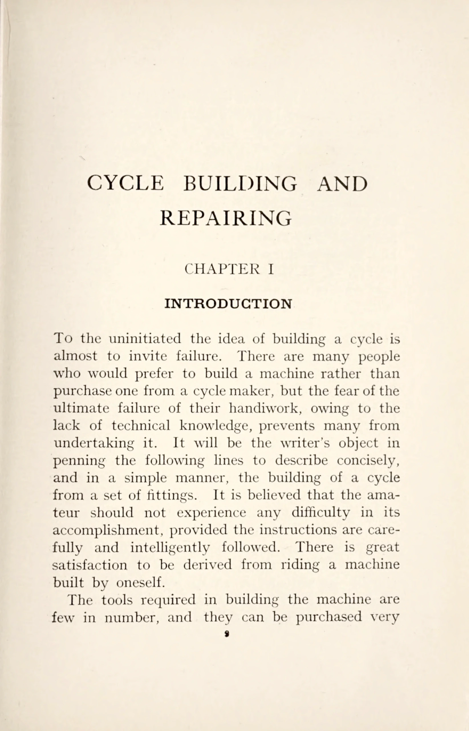 Page 13
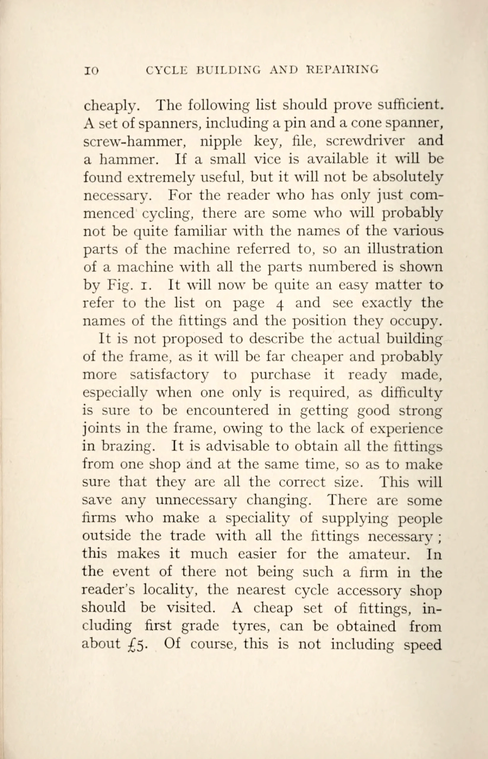 Page 14
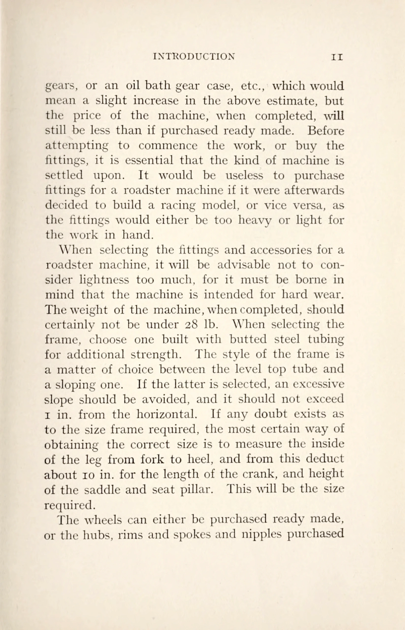 Page 15
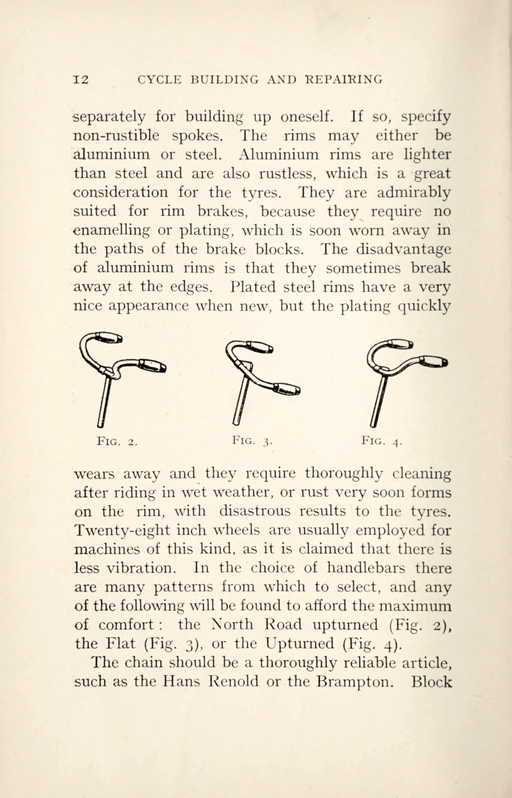 Page 16
 Page 17
 Page 18
 Page 19
 Page 20
 Page 21
 Page 22
 Page 23
 Page 24
 Page 25
 Page 26
 Page 27
 Page 28
 Page 29
 Page 30
 Page 31
 Page 32
 Page 33
 Page 34
 Page 35
 Page 36
 Page 37
 Page 38
 Page 39
 Page 40
 Page 41
 Page 42
 Page 43
 Page 44
 Page 45
 Page 46
 Page 47
 Page 48
 Page 49
 Page 50
 Page 51
 Page 52
 Page 53
 Page 54
 Page 55
 Page 56
 Page 57
 Page 58
 Page 59
 Page 60
 Page 61
 Page 62
 Page 63
 Page 64
 Page 65
 Page 66
 Page 67
 Page 68
 Page 69
 Page 70
 Page 71
 Page 72
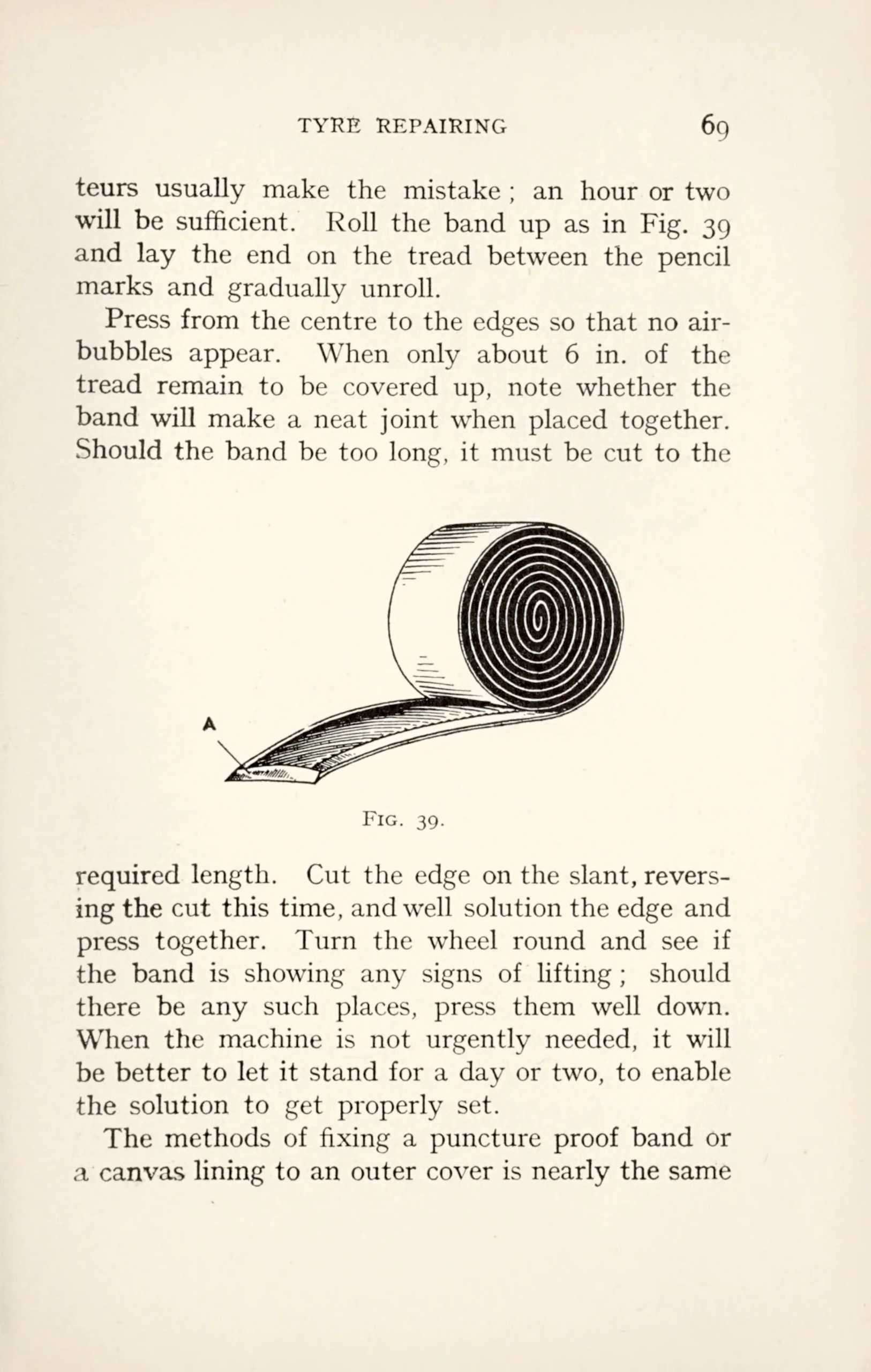 Page 73
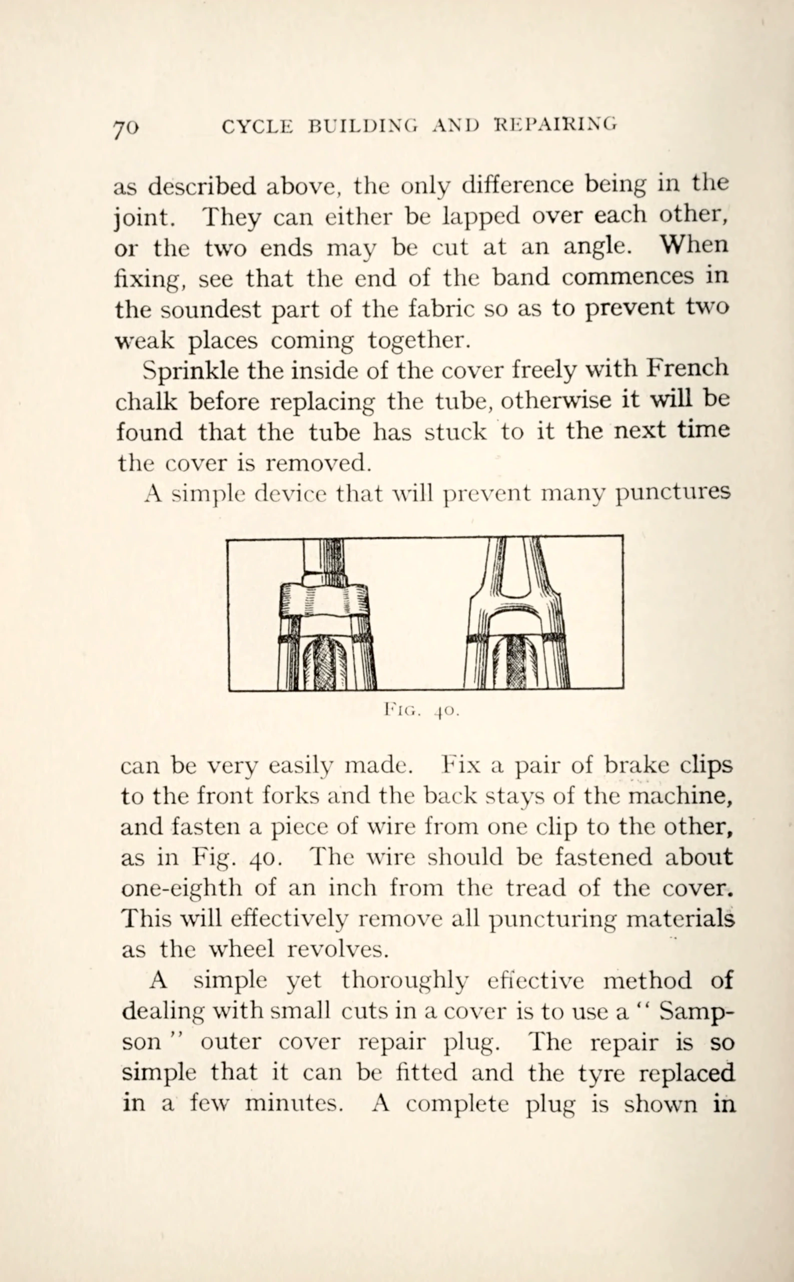 Page 74
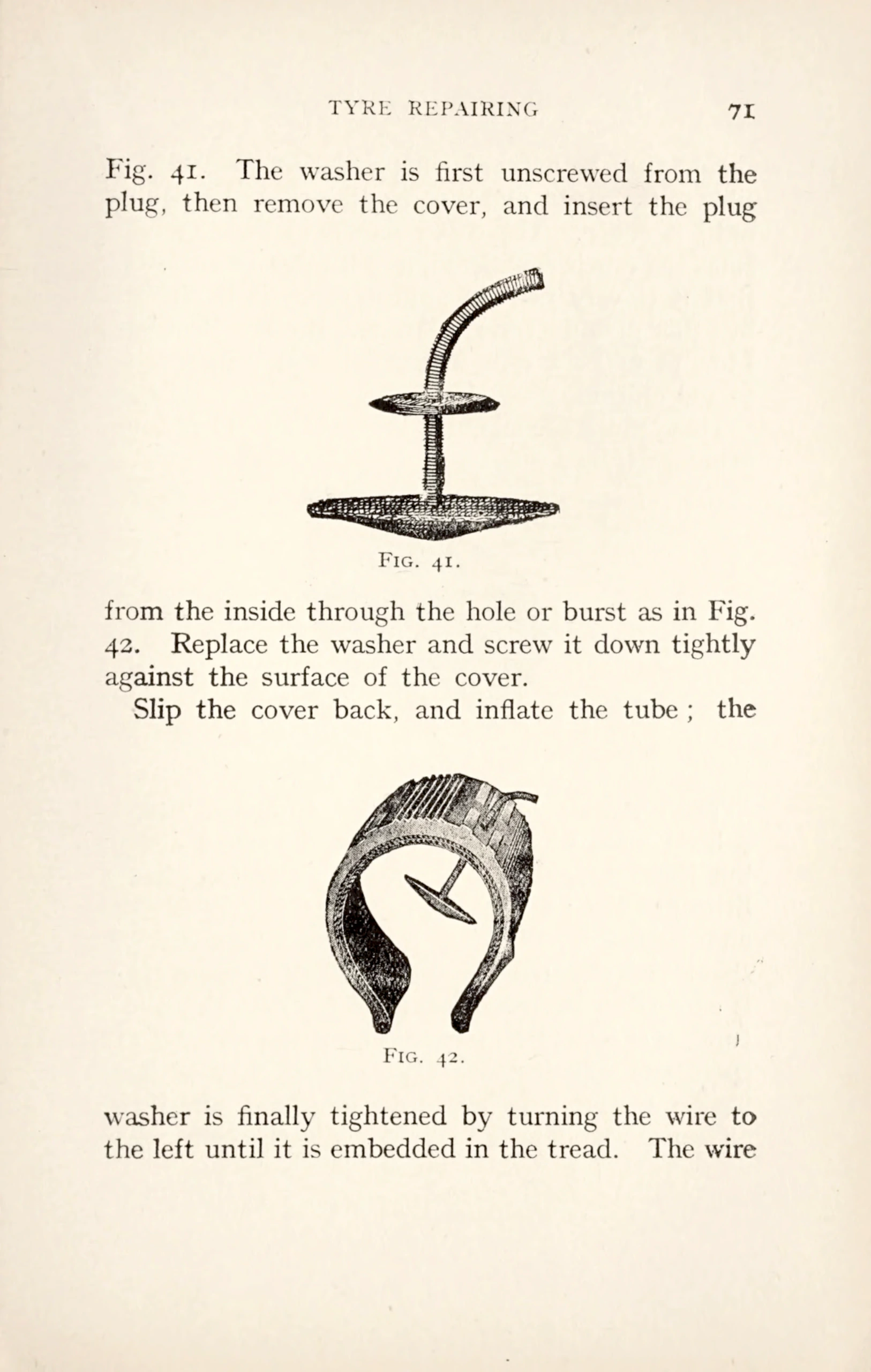 Page 75
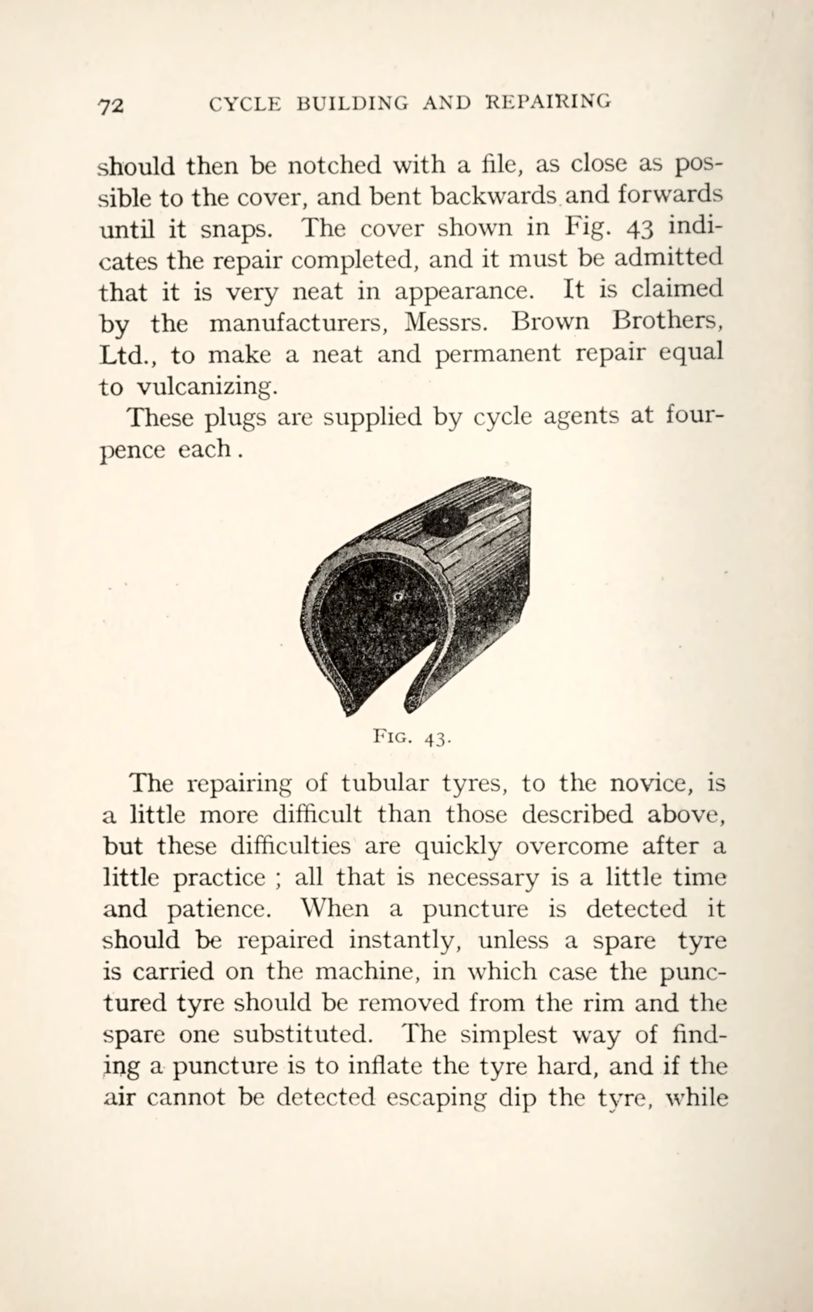 Page 76
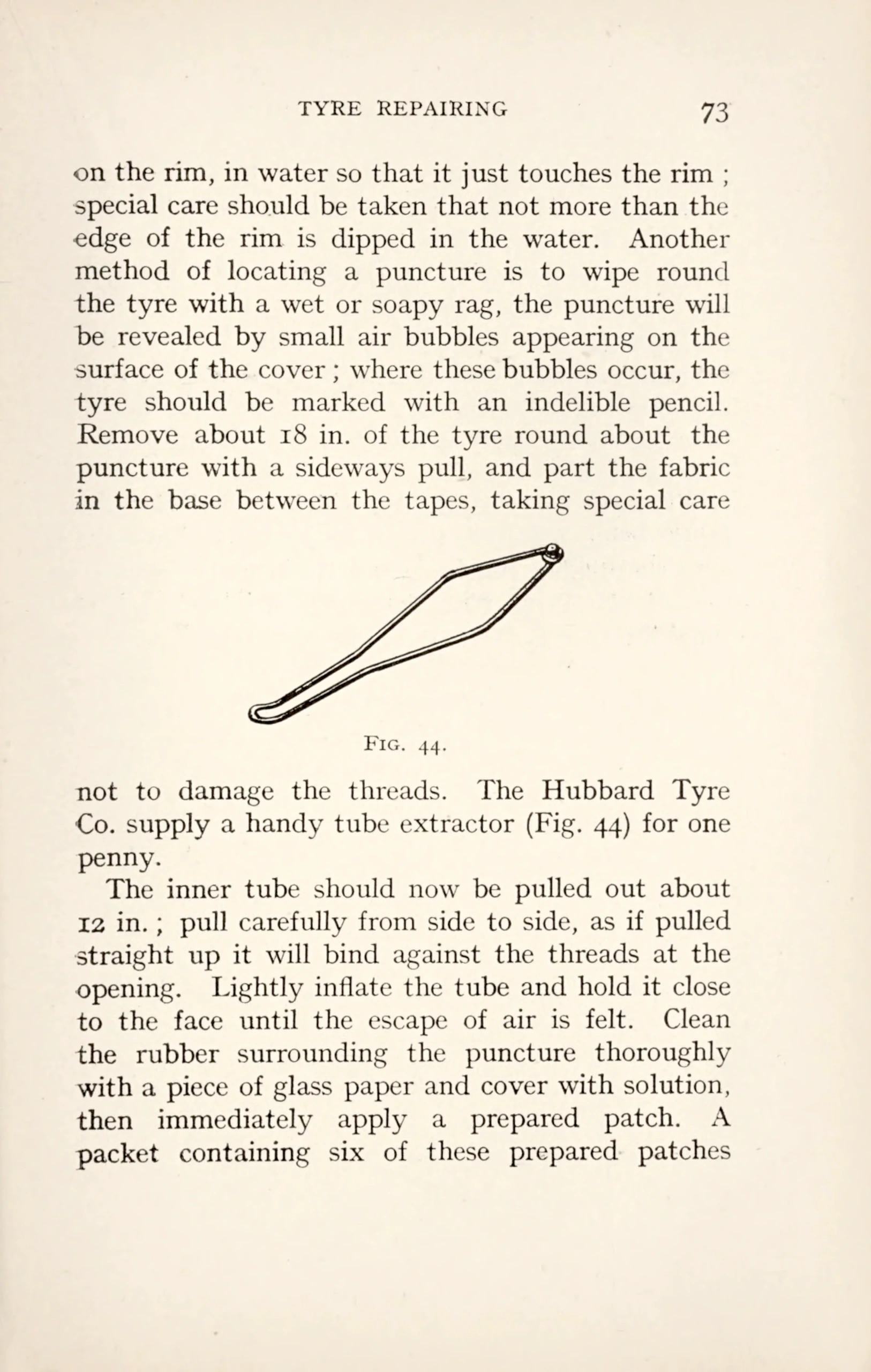 Page 77
 Page 78
 Page 79
 Page 80
 Page 81
 Page 82
 Page 83
 Page 84
 Page 85
 Page 86
 Page 87
 Page 88
 Page 89
 Page 90
 Page 91
 Page 92
 Page 93
 Page 94
 Page 95
 Page 96
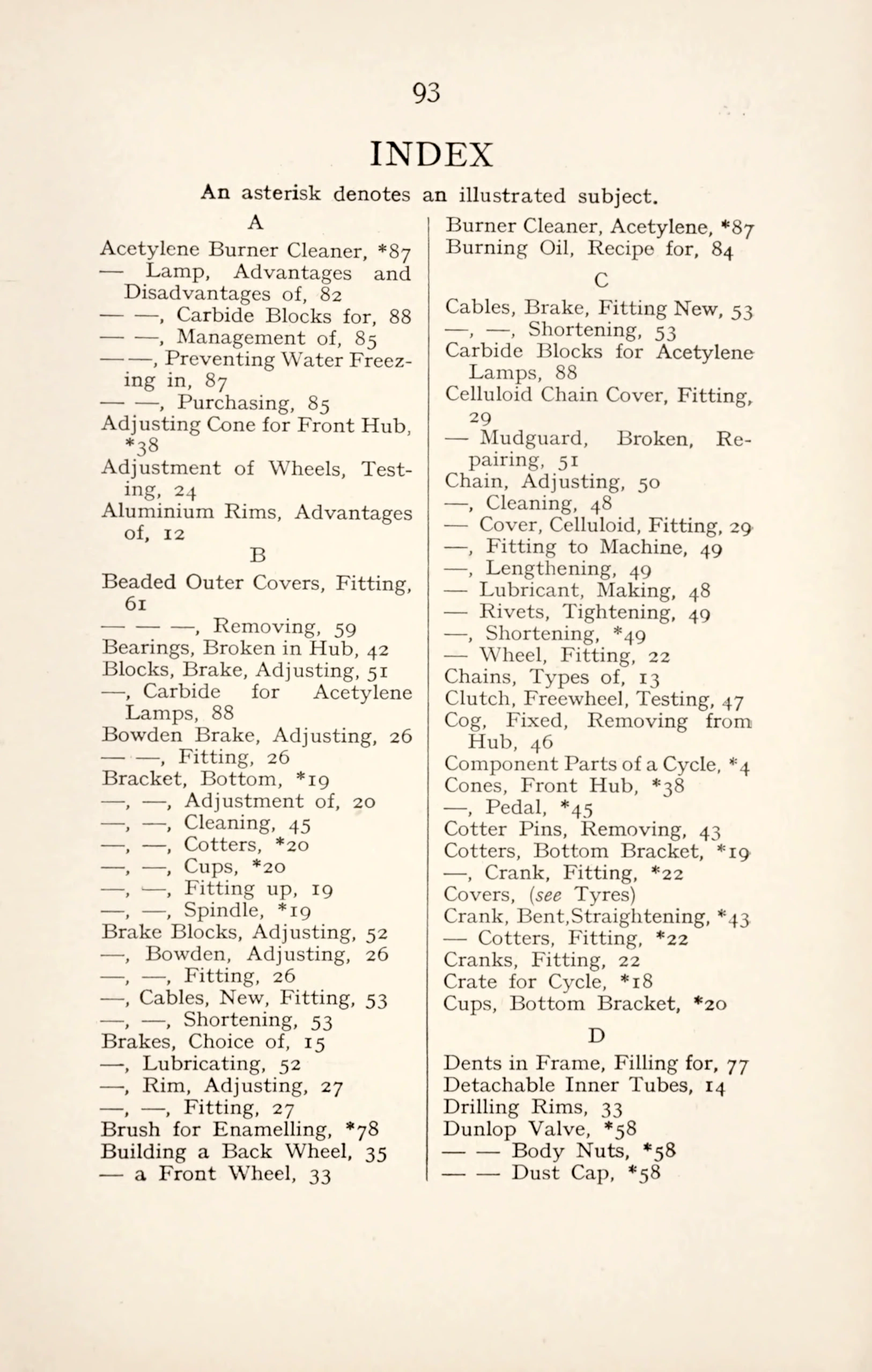 Page 97
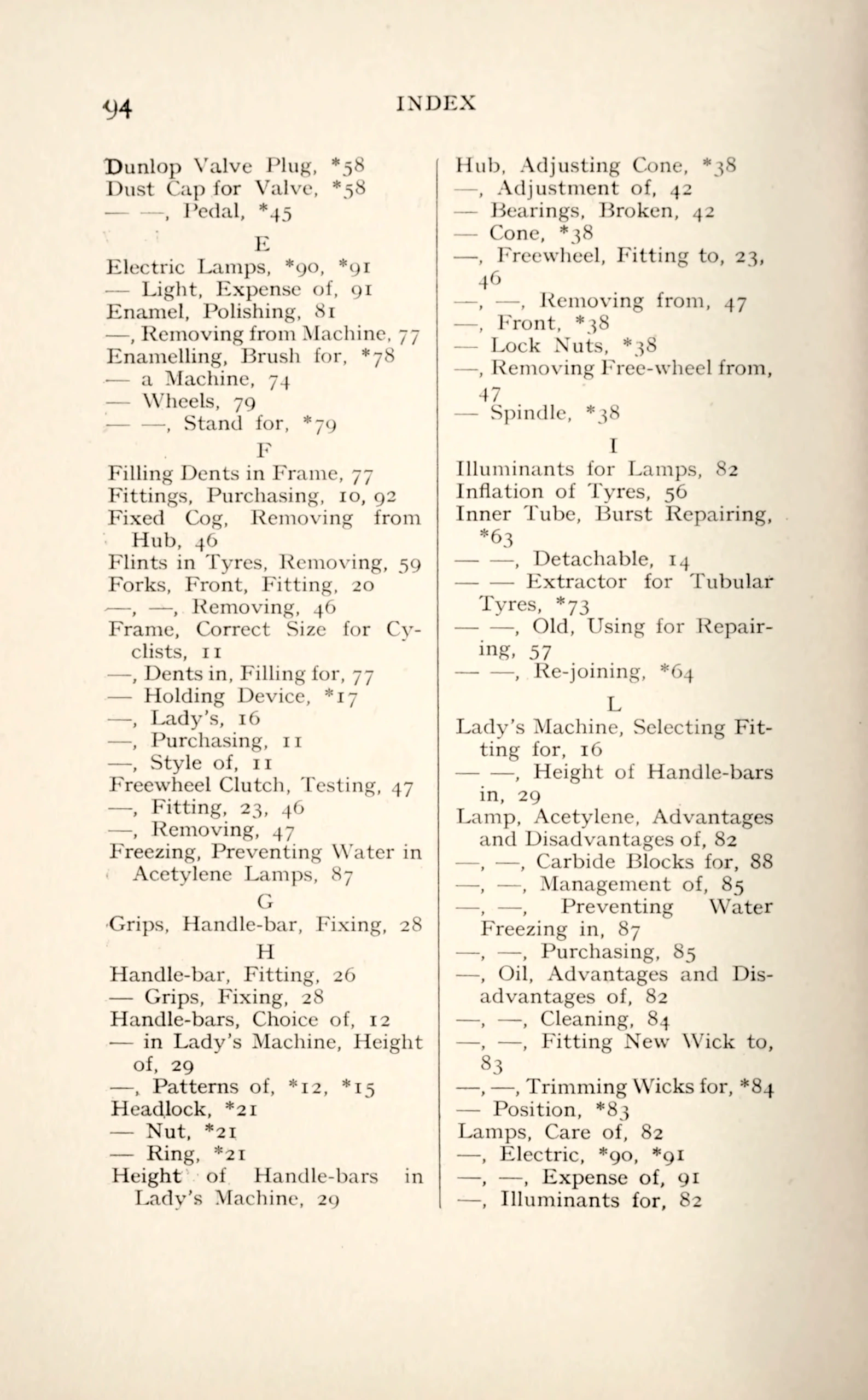 Page 98
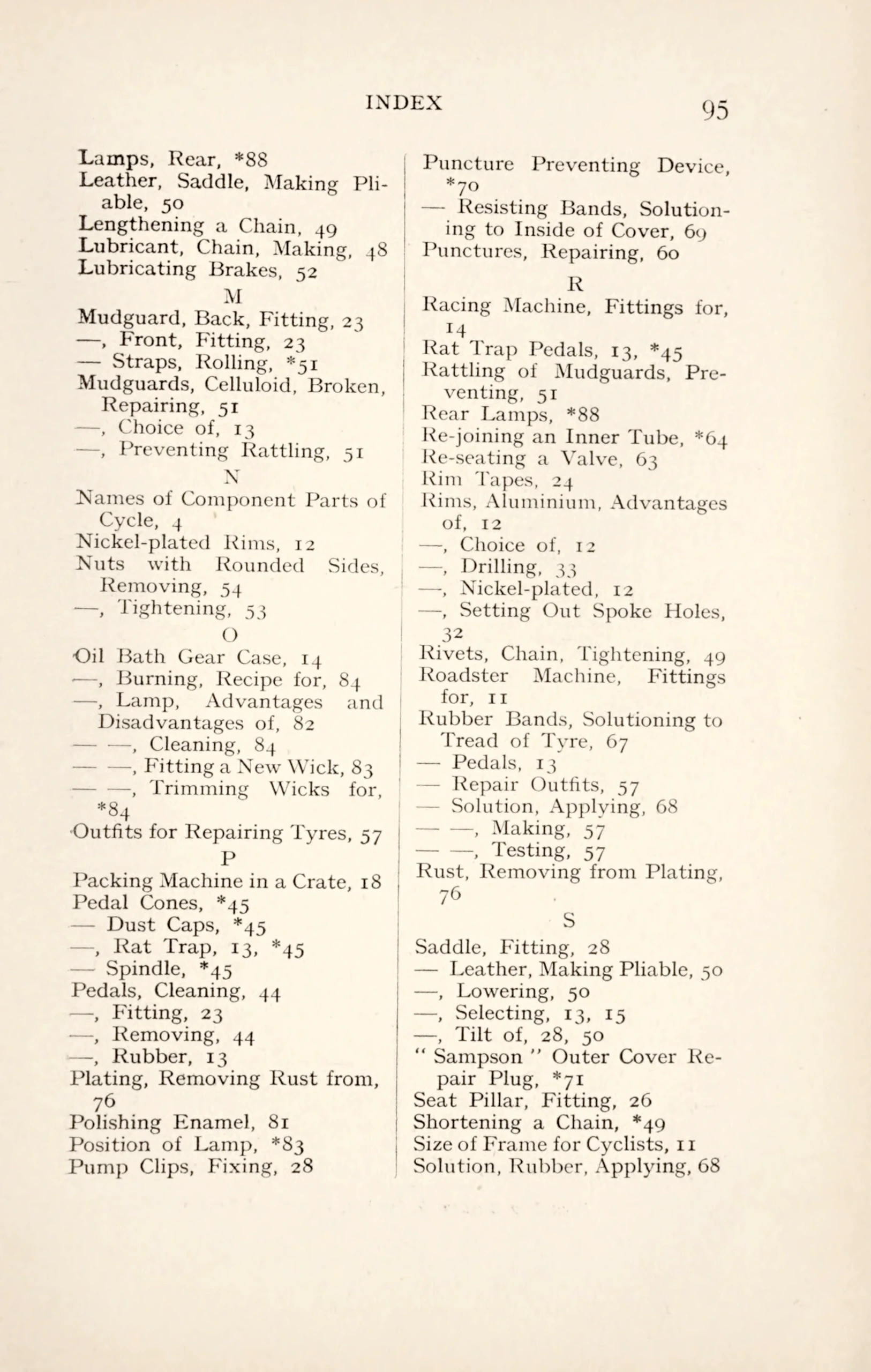 Page 99
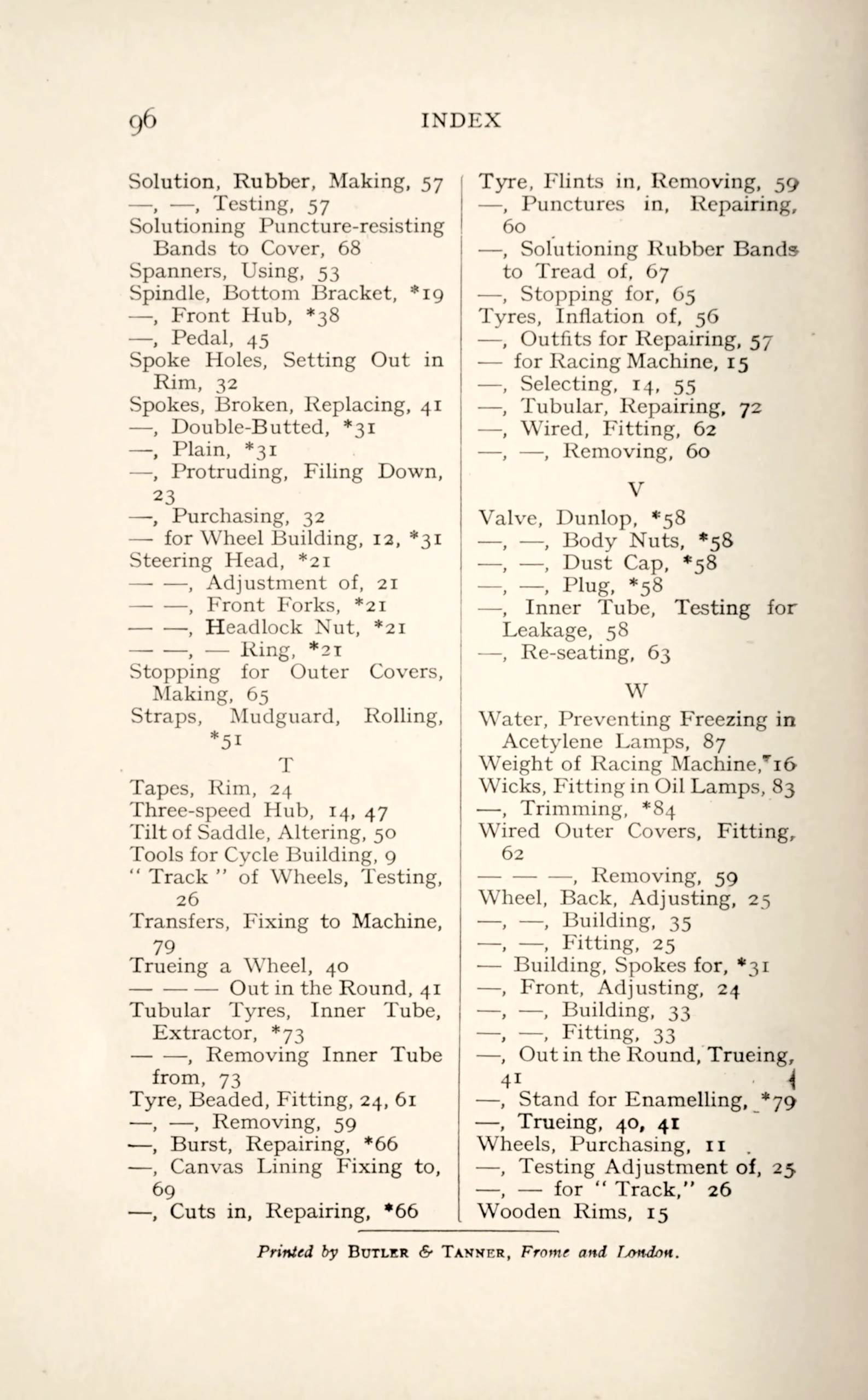 Page 100
 Page 101
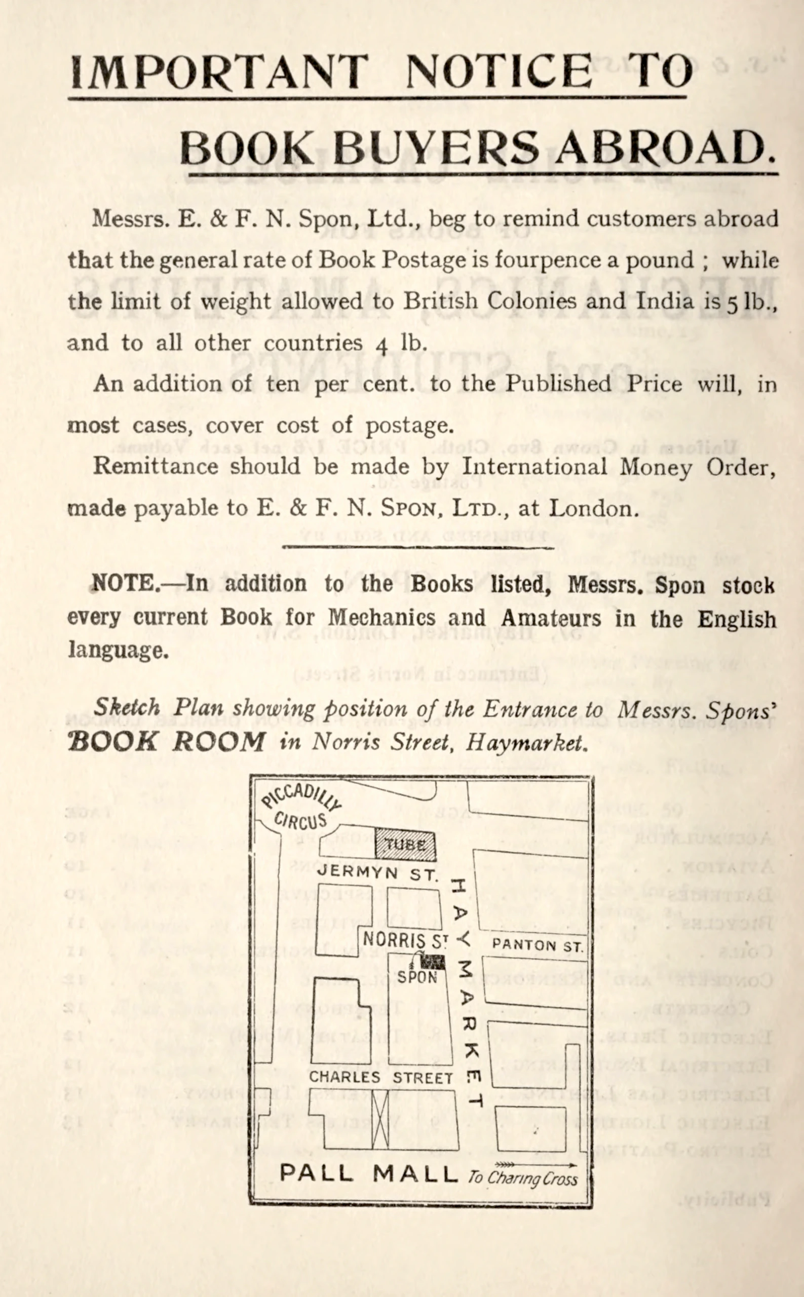 Page 102
 Page 103
 Page 104
 Page 105
 Page 106
 Page 107
 Page 108
 Page 109
 Page 110
 Page 111
 Page 112
 Page 113
 Page 114
 Page 115
 Page 116
 Page 117
 Page 118
 Page 119
 Page 120
| Type | Instructions |
|---|---|
| Year | 1913 |
| Publisher | E. & F. N. Spon, Ltd, London, and Spon and Chamberlain, New York |
| Country | England |
| Language | English |
| Pages | 120 |
| Source | Internet Archive item cyclebuildingrep00henr, a Library of Congress copy whose record states no copyright; page images are the archive's processed single-page JPEG 2000 files, toned for Ebykr. |
| Credit | Library of Congress, via the Internet Archive (public domain); Ebykr archive |
| Identifier | Permalink https://archive.org/details/cyclebuildingrep00henr |
| Transcription | Transcribed by eye |
Reference
E. & F. N. Spon, Ltd, London, and Spon and Chamberlain, New York. Peter Henry's Cycle Building and Repairing, 1913: Building a Machine and Its Wheels, Simple Repairs, Tire Repairing, Enameling and the Care of the Lamp (S. & C. Series 43). 1913. Ebykr, https://ebykr.com/library/henry-cycle-building-and-repairing-1913/.
Wikipedia
{{cite book |title=Peter Henry's Cycle Building and Repairing, 1913: Building a Machine and Its Wheels, Simple Repairs, Tire Repairing, Enameling and the Care of the Lamp (S. & C. Series 43) |publisher=E. & F. N. Spon, Ltd, London, and Spon and Chamberlain, New York |date=1913 |url=https://ebykr.com/library/henry-cycle-building-and-repairing-1913/ |via=Ebykr |access-date=}}THE S & C SERIES No. 43 CYCLE BUILDING AND REPAIRING PETER HENRY 1s/6d NET CYCLE BUILDING AND REPAIRING Fig. 1. The Parts of a Cycle. 1. Top Tube. 2. Seat Tube. 3. Bottom Tube. 4. Head Tube. 5. Chain Stay. 6. Seat Stay. 7. Lugs. 8. Saddle. 9. Saddle Peak. 10. Saddle Springs. 11. …
One hundred and twenty pages of Peter Henry’s Cycle Building and Repairing, 1913 (The S. & C. Series No. 43): building a machine and its wheels, simple repairs, tire repairing, enameling and the care of the lamp, with an index and the publisher’s book lists.
— Page 1 (front cover) —
THE S & C SERIES
No. 43
CYCLE BUILDING
AND REPAIRING
PETER HENRY
1s/6d NET
[The front board of a brown cloth binding stamped in black with “Cycle Building and Repairing” and the author’s name Peter Henry, inside a border of repeating ornament at the top and bottom edges. A circled price mark sits near the bottom and a small white library call-number label is pasted at the top left corner; the cloth is rubbed and the edges are worn.]
— Page 2 (inside front cover) —
[A blank cream endpaper with a Library of Congress bookplate pasted at the center, showing an eagle above a circular seal with the date 1800 and two printed ruled lines for a class and a book number, both filled in by hand in pencil. The right edge of the sheet shows vertical ribbing from the binding hinge.]
— Page 3 —
[A blank tan flyleaf with no printed lettering, showing a lifted torn corner at the top left, a ribbed strip along the left edge and small specks across the sheet. A few faint small marks of unclear kind sit near the left edge about a quarter of the way down.]
— Page 4 —
[A blank tan flyleaf with no printed lettering, stained yellow and brown along the right edge and torn at the top right corner, where a fold of paper has chipped away.]
— Page 5 —
CYCLE BUILDING AND
REPAIRING
[A half-title page with the words “Cycle Building and Repairing” in capitals near the middle of a cream sheet. A broad yellow-brown stain covers the left edge and the paper is chipped along it.]
— Page 6 —
[A blank flyleaf with no printed lettering, its paper stained yellow and brown toward the right edge and darker along the left edge. A faint ghost of the printing from the facing sheet shows through near the middle.]
— Page 7 —
[A blank flyleaf with no printed lettering, its paper stained yellow and brown around all four edges and darkest at the left edge. A faint ghost of the drawing on the facing plate shows through the center of the sheet.]
— Page 8 —
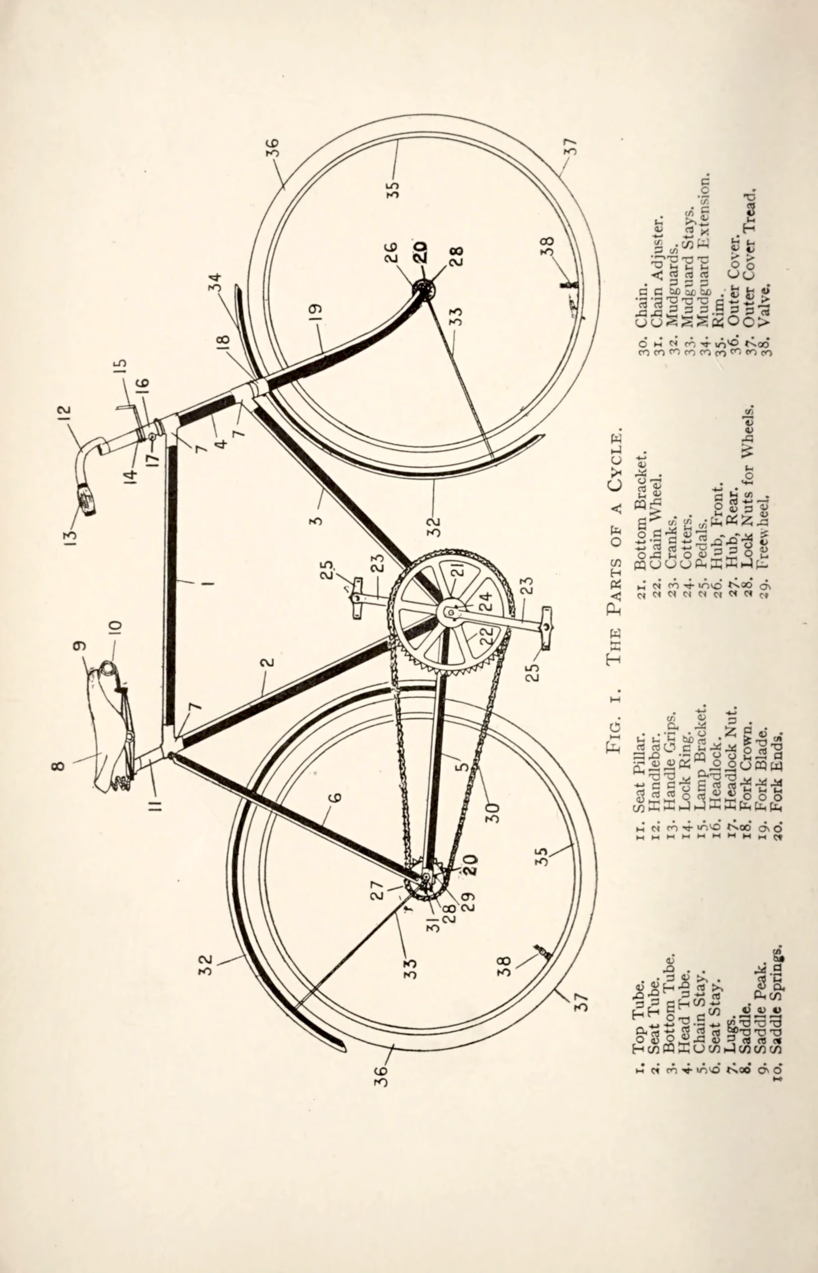
Fig. 1. The Parts of a Cycle.
1. Top Tube.
2. Seat Tube.
3. Bottom Tube.
4. Head Tube.
5. Chain Stay.
6. Seat Stay.
7. Lugs.
8. Saddle.
9. Saddle Peak.
10. Saddle Springs.
11. Seat Pillar.
12. Handlebar.
13. Handle Grips.
14. Lock Ring.
15. Lamp Bracket.
16. Headlock.
17. Headlock Nut.
18. Fork Crown.
19. Fork Blade.
20. Fork Ends.
21. Bottom Bracket.
22. Chain Wheel.
23. Cranks.
24. Cotters.
25. Pedals.
26. Hub, Front.
27. Hub, Rear.
28. Lock Nuts for Wheels.
29. Freewheel.
30. Chain.
31. Chain Adjuster.
32. Mudguards.
33. Mudguard Stays.
34. Mudguard Extension.
35. Rim.
36. Outer Cover.
37. Outer Cover Tread.
38. Valve.
Callouts: 8 9 10 13 12 15 14 16 17 11 7 1 7 4 7 18 34 32 2 3 6 19 36 25 23 36 33 27 26 20 35 21 22 24 31 28 29 20 5 30 23 25 32 33 28 38 35 37 38 37
[Fig. 1, The Parts of a Cycle, a line drawing of a diamond-frame bicycle with 38 numbered parts, printed sideways across the plate with a four-column key beneath it. The drawing shows the frame, saddle, handlebar, chain wheel, cranks, chain, mudguards and both wheels with their tires and valves.]
— Page 9 —
CYCLE BUILDING
AND REPAIRING
INCLUDING
CARE OF LAMP, ENAMELLING, REPAIR
OF TYRES AND WHEEL BUILDING
By
PETER HENRY
55 ILLUSTRATIONS
LONDON
E. & F. N. SPON, LTD., 57, HAYMARKET
NEW YORK
SPON & CHAMBERLAIN, 123, LIBERTY STREET
1913
[The title page of Cycle Building and Repairing by Peter Henry, with 55 illustrations, published in London by E. & F. N. Spon and in New York by Spon and Chamberlain, with an interlaced monogram device above the imprint. A small gray smudge sits under the author’s name and a faint cluster of punched holes lies below the monogram.]
— Page 10 —
[The back of the title page, a stained cream sheet with no printed lettering. Later marks include a pencil call number at the upper right, handwritten ink figures near the middle, a ring of punched holes beside a short column of holes below them, and ink figures near the bottom; the title page shows faintly through the paper at the top.]
— Page 11 —
CONTENTS
CHAP. PAGE
I Introduction …. 9
II Building a Machine …. 19
III Building the Wheels …. 31
IV Simple Repairs …. 40
V Tyre Repairing …. 55
VI Cycle Enamelling …. 75
VII The Care of the Lamp …. 82
Index …. 93
7
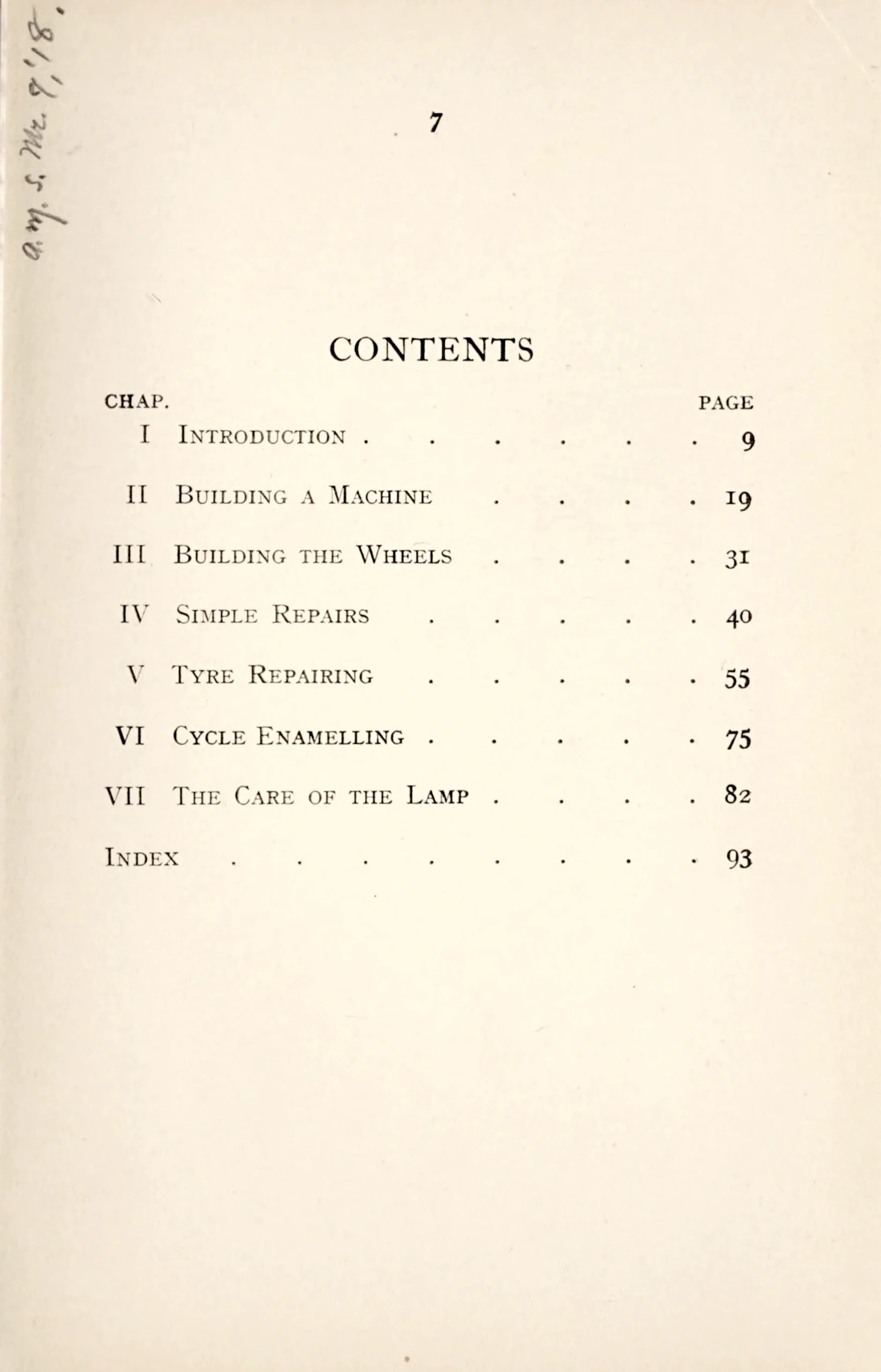
[The Contents page of Cycle Building and Repairing, listing seven chapters from Introduction to The Care of the Lamp and the Index with their page numbers, set with dot leaders. A line of handwriting in pencil runs up the left margin beside the top corner.]
— Page 12 —
[A blank cream sheet with no printed lettering, browned and stained yellow along the left and right edges. The dot leaders of the Contents show faintly through the paper.]
— Page 13 —
CYCLE BUILDING AND REPAIRING
CHAPTER I
INTRODUCTION
To the uninitiated the idea of building a cycle is almost to invite failure. There are many people who would prefer to build a machine rather than purchase one from a cycle maker, but the fear of the ultimate failure of their handiwork, owing to the lack of technical knowledge, prevents many from undertaking it. It will be the writer’s object in penning the following lines to describe concisely, and in a simple manner, the building of a cycle from a set of fittings. It is believed that the amateur should not experience any difficulty in its accomplishment, provided the instructions are carefully and intelligently followed. There is great satisfaction to be derived from riding a machine built by oneself.
The tools required in building the machine are few in number, and they can be purchased very
9
[The first page of Chapter I, Introduction, in Cycle Building and Repairing, with the book title and chapter heading above the opening paragraphs on building a cycle from a set of fittings.]
— Page 14 —
10 CYCLE BUILDING AND REPAIRING
cheaply. The following list should prove sufficient. A set of spanners, including a pin and a cone spanner, screw-hammer, nipple key, file, screwdriver and a hammer. If a small vice is available it will be found extremely useful, but it will not be absolutely necessary. For the reader who has only just commenced cycling, there are some who will probably not be quite familiar with the names of the various parts of the machine referred to, so an illustration of a machine with all the parts numbered is shown by Fig. 1. It will now be quite an easy matter to refer to the list on page 4 and see exactly the names of the fittings and the position they occupy.
It is not proposed to describe the actual building of the frame, as it will be far cheaper and probably more satisfactory to purchase it ready made, especially when one only is required, as difficulty is sure to be encountered in getting good strong joints in the frame, owing to the lack of experience in brazing. It is advisable to obtain all the fittings from one shop and at the same time, so as to make sure that they are all the correct size. This will save any unnecessary changing. There are some firms who make a speciality of supplying people outside the trade with all the fittings necessary ; this makes it much easier for the amateur. In the event of there not being such a firm in the reader’s locality, the nearest cycle accessory shop should be visited. A cheap set of fittings, including first grade tyres, can be obtained from about £5. Of course, this is not including speed
[A page of running text from Chapter I, Introduction, in Cycle Building and Repairing, on the tools needed and on buying a ready made frame and a set of fittings.]
— Page 15 —
INTRODUCTION 11
gears, or an oil bath gear case, etc., which would mean a slight increase in the above estimate, but the price of the machine, when completed, will still be less than if purchased ready made. Before attempting to commence the work, or buy the fittings, it is essential that the kind of machine is settled upon. It would be useless to purchase fittings for a roadster machine if it were afterwards decided to build a racing model, or vice versa, as the fittings would either be too heavy or light for the work in hand.
When selecting the fittings and accessories for a roadster machine, it will be advisable not to consider lightness too much, for it must be borne in mind that the machine is intended for hard wear. The weight of the machine, when completed, should certainly not be under 28 lb. When selecting the frame, choose one built with butted steel tubing for additional strength. The style of the frame is a matter of choice between the level top tube and a sloping one. If the latter is selected, an excessive slope should be avoided, and it should not exceed 1 in. from the horizontal. If any doubt exists as to the size frame required, the most certain way of obtaining the correct size is to measure the inside of the leg from fork to heel, and from this deduct about 10 in. for the length of the crank, and height of the saddle and seat pillar. This will be the size required.
The wheels can either be purchased ready made, or the hubs, rims and spokes and nipples purchased
[A page of running text from Chapter I, Introduction, in Cycle Building and Repairing, on choosing the kind of machine, the weight of a roadster and the size of the frame.]
— Page 16 —
12 CYCLE BUILDING AND REPAIRING
separately for building up oneself. If so, specify non-rustible spokes. The rims may either be aluminium or steel. Aluminium rims are lighter than steel and are also rustless, which is a great consideration for the tyres. They are admirably suited for rim brakes, because they require no enamelling or plating, which is soon worn away in the paths of the brake blocks. The disadvantage of aluminium rims is that they sometimes break away at the edges. Plated steel rims have a very nice appearance when new, but the plating quickly
Fig. 2. Fig. 3. Fig. 4.
wears away and they require thoroughly cleaning after riding in wet weather, or rust very soon forms on the rim, with disastrous results to the tyres. Twenty-eight inch wheels are usually employed for machines of this kind, as it is claimed that there is less vibration. In the choice of handlebars there are many patterns from which to select, and any of the following will be found to afford the maximum of comfort : the North Road upturned (Fig. 2), the Flat (Fig. 3), or the Upturned (Fig. 4).
The chain should be a thoroughly reliable article, such as the Hans Renold or the Brampton. Block
[Three line drawings of handlebars with grips, each fitted to a short stem, captioned Fig. 2, Fig. 3 and Fig. 4, set between paragraphs of text on rims, wheels and handlebars.]
— Page 17 —
INTRODUCTION 13
chains are very seldom used ; these do not run so easily as the roller variety, so the latter should be selected.
The pedals in general use are the rat-trap and the rubber. The rubber will be found to afford a better footing, unless toe-clips are used. Rat-trap pedals have the advantage of being lighter, but this will hardly matter with machines of this kind. The saddle is one of the most important details of the cycle, for upon this the whole of the rider’s comfort and enjoyment depend. It is a great mistake to select a saddle solely for its neat appearance, some of them being practically springless.
A large, comfortable saddle with plenty of springs should be selected, that is, if one desires real comfort. The Brooks B302 or B90 can be thoroughly recommended. It is advisable to select an enamelled spring saddle in preference to one with plated springs. Not only is it cheaper, but it requires less cleaning and attention. The plated springs frequently rust away unnoticed, until they snap.
The mudguards may either be steel or celluloid, though aluminium is sometimes employed. They should be of ample dimensions, to thoroughly protect the machine.
Two efficient brakes are really necessary. They may either be rim, hub or band brakes. With the coaster hub the chief drawbacks are, the extra weight in the back hub, and the fact that the brake cannot be effectively applied at every position in the revolution of the pedals. If a coaster hub is
[A page of running text from Chapter I, Introduction, in Cycle Building and Repairing, on chains, pedals, saddles, mudguards and brakes, naming the Brooks B302 and B90 saddles.]
— Page 18 —
14 CYCLE BUILDING AND REPAIRING
used, a rim brake should always be fitted to the front wheel, as an additional safeguard in case of the chain breaking or the hub brake failing to act. In the case of repairs, it is much easier to remove a wheel fitted with a coaster hub than the wheel of a rim brake machine.
If a three-speed gear is fitted, which will almost be an essential article for a tourist machine, a choice between the Sturmey Archer and the Armstrong will be found to give every satisfaction. The chain is kept clean and in beautiful condition if an oil bath gear case is fitted, though of course this will add considerably to the weight of the machine.
Only thoroughly reliable tyres such as the Palmer, Hubbard or Dunlop should be used, for it is purely a waste of money to have a machine fitted with inferior tyres, as they are always a source of worry and trouble to the owner. The tyres should not be less than 1½ in., and should have an extra thick tread.
Puncture resisting bands could also be fitted to the cover for additional security. Extra thick tubes should be used ; if they are detachable so much the better, as it will facilitate repairs.
A racing model differs entirely from the model described above ; with the roadster, weight was not taken into consideration, but with a racing model it must be as light as possible, combined with great strength. The frame should be built with the best and lightest steel tubing.
The wheels should be 26 in. Wooden rims are
[A page of running text from Chapter I, Introduction, in Cycle Building and Repairing, on coaster hubs, three speed gears, tires and the differences in a racing model, naming the Sturmey Archer and the Armstrong.]
— Page 19 —
INTRODUCTION 15
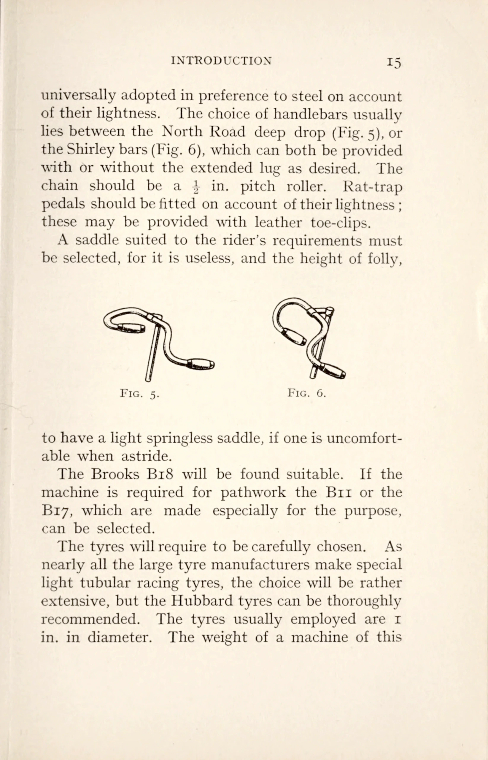
universally adopted in preference to steel on account of their lightness. The choice of handlebars usually lies between the North Road deep drop (Fig. 5), or the Shirley bars (Fig. 6), which can both be provided with or without the extended lug as desired. The chain should be a ½ in. pitch roller. Rat-trap pedals should be fitted on account of their lightness ; these may be provided with leather toe-clips.
A saddle suited to the rider’s requirements must be selected, for it is useless, and the height of folly,
Fig. 5. Fig. 6.
to have a light springless saddle, if one is uncomfortable when astride.
The Brooks B18 will be found suitable. If the machine is required for pathwork the B11 or the B17, which are made especially for the purpose, can be selected.
The tyres will require to be carefully chosen. As nearly all the large tyre manufacturers make special light tubular racing tyres, the choice will be rather extensive, but the Hubbard tyres can be thoroughly recommended. The tyres usually employed are 1 in. in diameter. The weight of a machine of this
[Two line drawings of handlebars with grips, each fitted to a short stem, captioned Fig. 5 and Fig. 6, set between paragraphs of text on a racing model, handlebars, saddles and tires, naming Brooks saddle models B18, B11 and B17.]
— Page 20 —
16 CYCLE BUILDING AND REPAIRING
kind should be between 20 and 24 lb., that is without brakes and mudguards.
In selecting the fittings for a lady’s machine, see that there is sufficient space in the frame to provide ample dress clearance and also for mounting and dismounting. The wheels usually fitted are 26 or 28 in. ; the latter, in the writer’s opinion, look much the neater. The choice of handlebars is rather limited. The Flat (Fig. 3), or the Upturned (Fig. 4), will be found to afford the maximum of comfort. Celluloid handle grips to match the enamel will improve the appearance of the machine. The cranks should not exceed 6½ in. in length. A ½ in. pitch roller chain should be specified ; cheap chains quickly stretch and wear out, so pay a little extra and secure a reliable article. Rubber pedals are usually used on a lady’s machine. A saddle constructed with a short peak should invariably be selected. The Brooks B85 and B302 are both excellent saddles and can be thoroughly recommended. Steel mudguards provided with a front extension should be fitted. A close meshed dress guard will be an essential article, otherwise the skirt is liable to get damaged through becoming entangled in the spokes.
A chain cover is also needed to protect the skirt from the chain. It will also be found to protect the chain to a certain extent, but nothing compared with an oil bath gear case. Roller lever brakes will be found excellent, their action being very smooth. The inverted levers are no doubt
[A page of running text from Chapter I, Introduction, in Cycle Building and Repairing, on fittings for a lady’s machine, naming the Brooks B85 and B302 saddles.]
— Page 21 —
INTRODUCTION 17
neater, but owing to the cables being hidden from view it is impossible to see how they are wearing, so they are not advised. At the risk of repeating statements, if enjoyment while cycling is required, the tyres must not be of inferior quality. Beaded edge tyres are ideal for a lady’s machine, owing to the simplicity of detachment and replacement for repairs. They should be 1½ in. in diameter. When
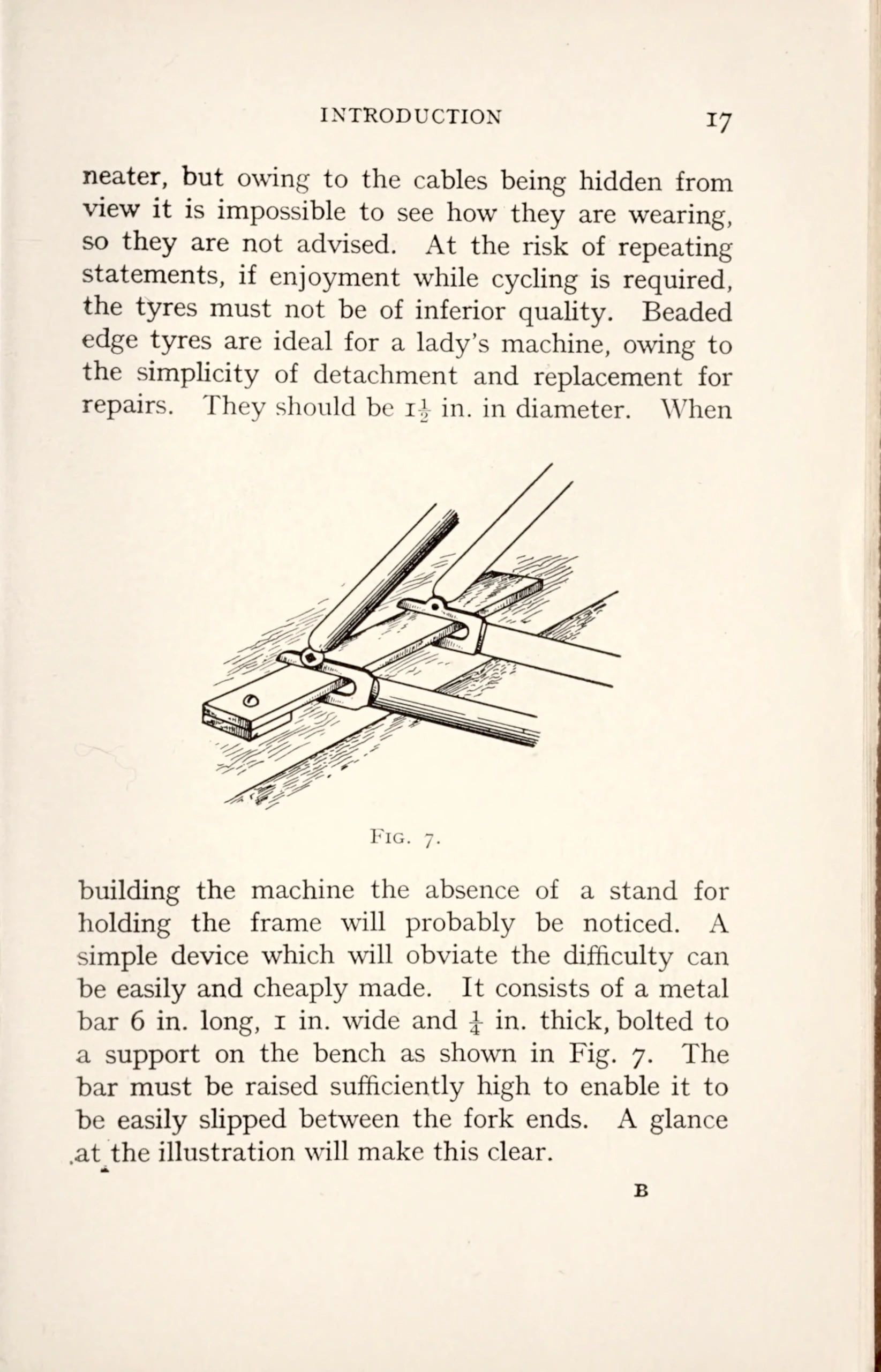
Fig. 7.
building the machine the absence of a stand for holding the frame will probably be noticed. A simple device which will obviate the difficulty can be easily and cheaply made. It consists of a metal bar 6 in. long, 1 in. wide and ¼ in. thick, bolted to a support on the bench as shown in Fig. 7. The bar must be raised sufficiently high to enable it to be easily slipped between the fork ends. A glance at the illustration will make this clear.
B
[A line drawing of two fork ends slipped over a metal bar bolted to a bench support, captioned Fig. 7, between paragraphs of text on a lady’s machine and a frame holder. A printer’s signature letter B is printed at the foot of the page, and the stacked page edges show as a dark strip down the right margin.]
— Page 22 —
18 CYCLE BUILDING AND REPAIRING
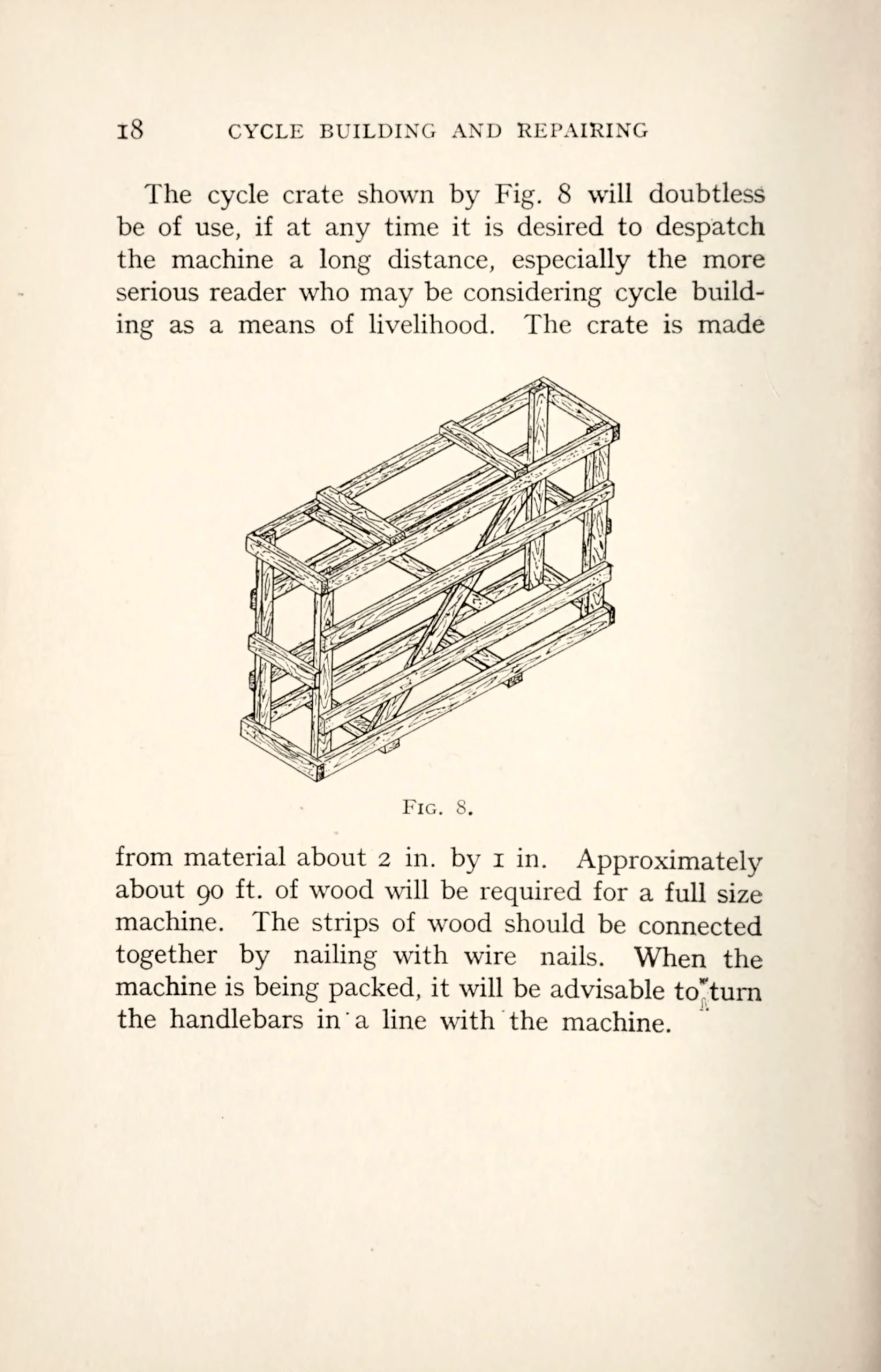
The cycle crate shown by Fig. 8 will doubtless be of use, if at any time it is desired to despatch the machine a long distance, especially the more serious reader who may be considering cycle building as a means of livelihood. The crate is made from material about 2 in. by 1 in. Approximately about 90 ft. of wood will be required for a full size machine. The strips of wood should be connected together by nailing with wire nails. When the machine is being packed, it will be advisable to turn the handlebars in a line with the machine.
Fig. 8.
[A wooden cycle crate drawn in perspective as an open frame of strips and braces, Fig. 8, set in the middle of a paragraph about packing a machine for despatch. A few faint specks of dirt mark the paper beside the last line but one.]
— Page 23 —
CHAPTER II
BUILDING A MACHINE
Having selected the fittings, it is now the reader’s opportunity to prove himself a skilled workman.
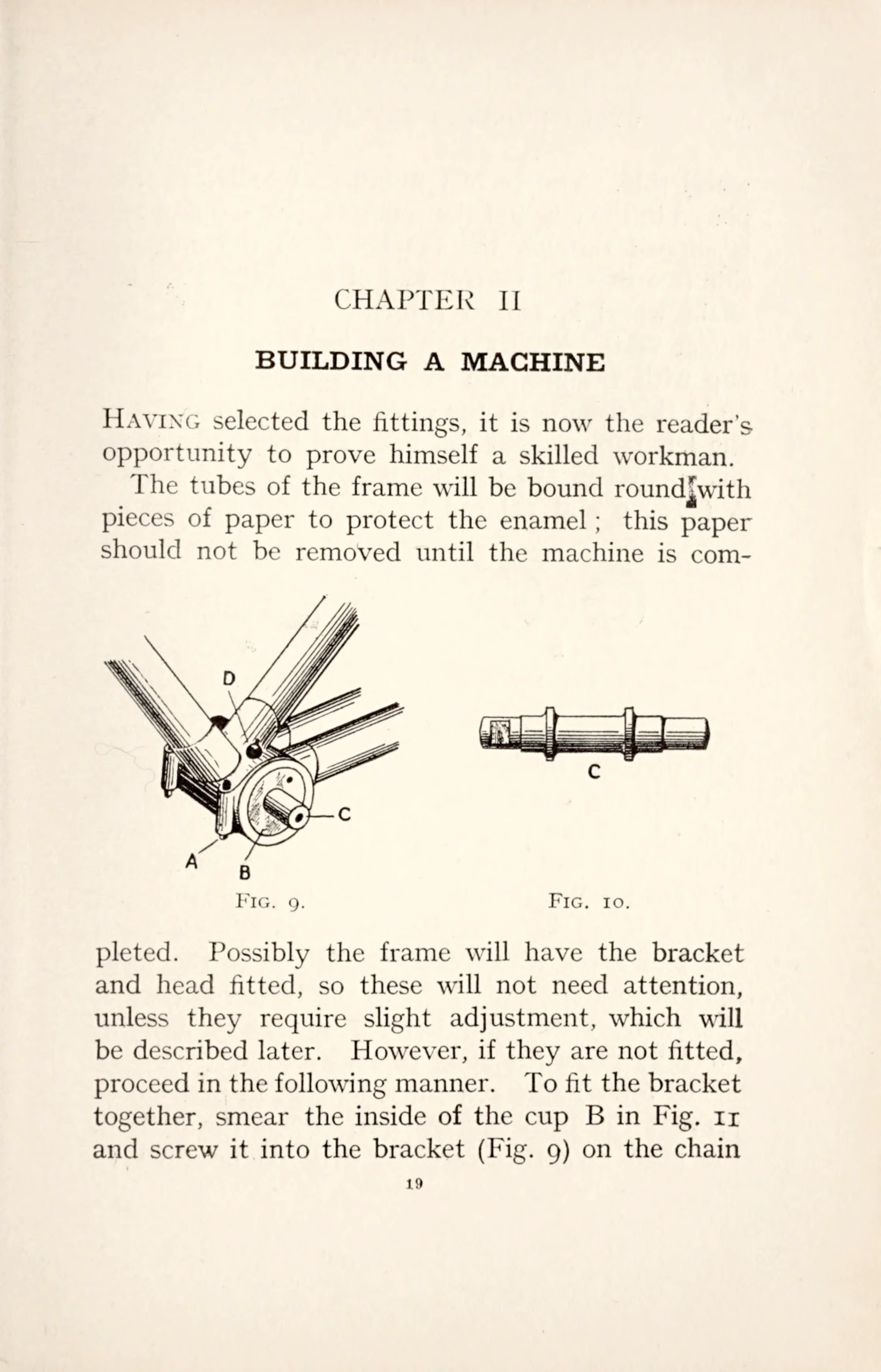
The tubes of the frame will be bound round with pieces of paper to protect the enamel; this paper should not be removed until the machine is completed. Possibly the frame will have the bracket and head fitted, so these will not need attention, unless they require slight adjustment, which will be described later. However, if they are not fitted, proceed in the following manner. To fit the bracket together, smear the inside of the cup B in Fig. 11 and screw it into the bracket (Fig. 9) on the chain
Fig. 9.
Callouts: A B C D
Fig. 10.
Callouts: C
19
[Chapter II, “Building a Machine,” opens with a paragraph and two line drawings: Fig. 9, a bottom bracket shell with the frame tubes lettered A to D, and Fig. 10, a bracket axle lettered C. A small dark ink speck sits between two words in the third line of text.]
— Page 24 —
20 CYCLE BUILDING AND REPAIRING
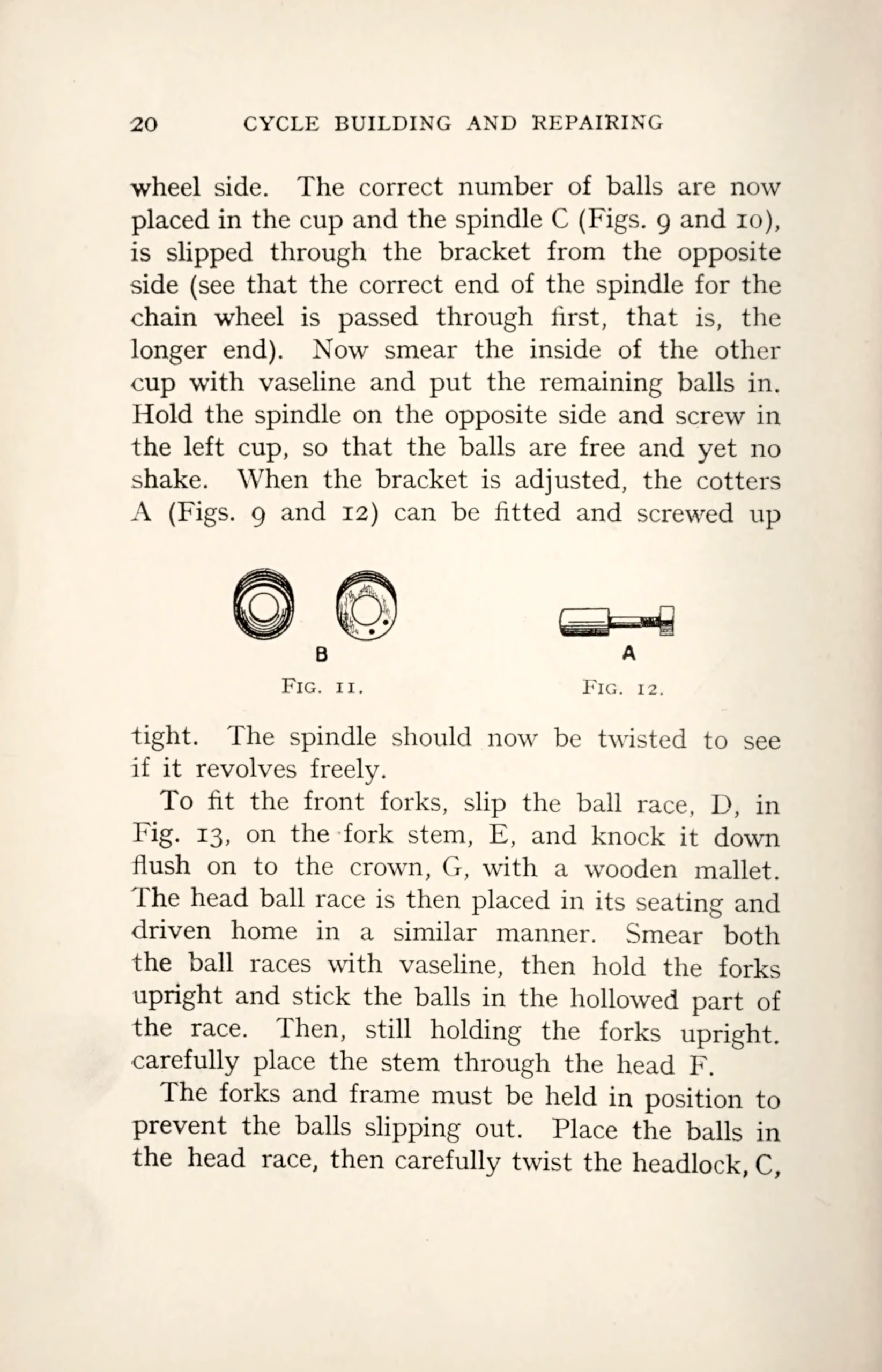
wheel side. The correct number of balls are now placed in the cup and the spindle C (Figs. 9 and 10), is slipped through the bracket from the opposite side (see that the correct end of the spindle for the chain wheel is passed through first, that is, the longer end). Now smear the inside of the other cup with vaseline and put the remaining balls in. Hold the spindle on the opposite side and screw in the left cup, so that the balls are free and yet no shake. When the bracket is adjusted, the cotters A (Figs. 9 and 12) can be fitted and screwed up tight. The spindle should now be twisted to see if it revolves freely.
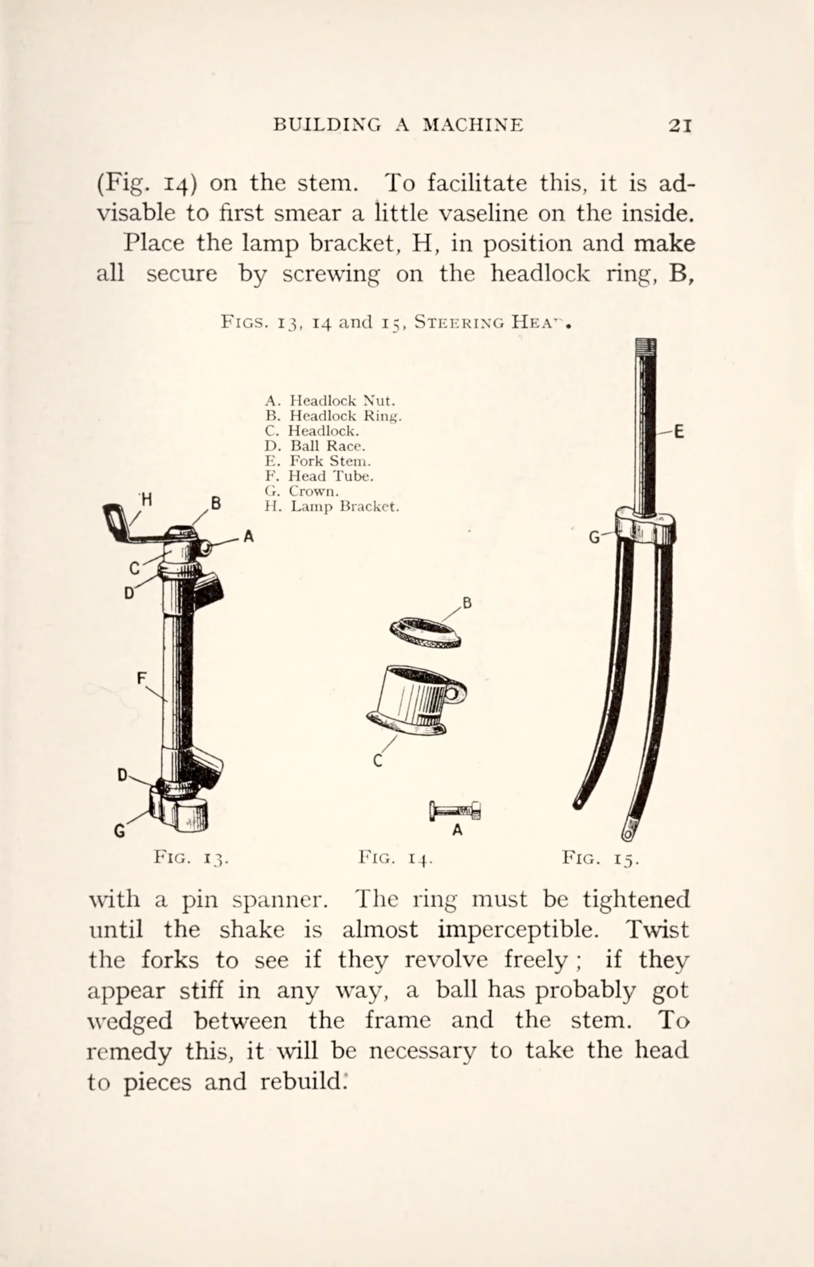
To fit the front forks, slip the ball race, D, in Fig. 13, on the fork stem, E, and knock it down flush on to the crown, G, with a wooden mallet. The head ball race is then placed in its seating and driven home in a similar manner. Smear both the ball races with vaseline, then hold the forks upright and stick the balls in the hollowed part of the race. Then, still holding the forks upright. carefully place the stem through the head F.
The forks and frame must be held in position to prevent the balls slipping out. Place the balls in the head race, then carefully twist the headlock, C,
Fig. 11.
Callouts: B
Fig. 12.
Callouts: A
[Two small line drawings between paragraphs of text: Fig. 11, a pair of bracket cups lettered B, and Fig. 12, a cotter pin lettered A.]
— Page 25 —
BUILDING A MACHINE 21
(Fig. 14) on the stem. To facilitate this, it is advisable to first smear a little vaseline on the inside.
Place the lamp bracket, H, in position and make all secure by screwing on the headlock ring, B, with a pin spanner. The ring must be tightened until the shake is almost imperceptible. Twist the forks to see if they revolve freely ; if they appear stiff in any way, a ball has probably got wedged between the frame and the stem. To remedy this, it will be necessary to take the head to pieces and rebuild.
Figs. 13, 14 and 15, Steering Head[?].
A. Headlock Nut.
B. Headlock Ring.
C. Headlock.
D. Ball Race.
E. Fork Stem.
F. Head Tube.
G. Crown.
H. Lamp Bracket.
Fig. 13.
Callouts: H B A C D F D G
Fig. 14.
Callouts: B C A
Fig. 15.
Callouts: E G
[Three line drawings of the steering head, Figs. 13, 14 and 15: the head tube with headlock, ball races, crown and lamp bracket; the headlock ring, headlock and nut; and the front fork with its stem. A key lists the lettered parts A to H, and the last letter of the group caption is partly lost.]
— Page 26 —
22 CYCLE BUILDING AND REPAIRING
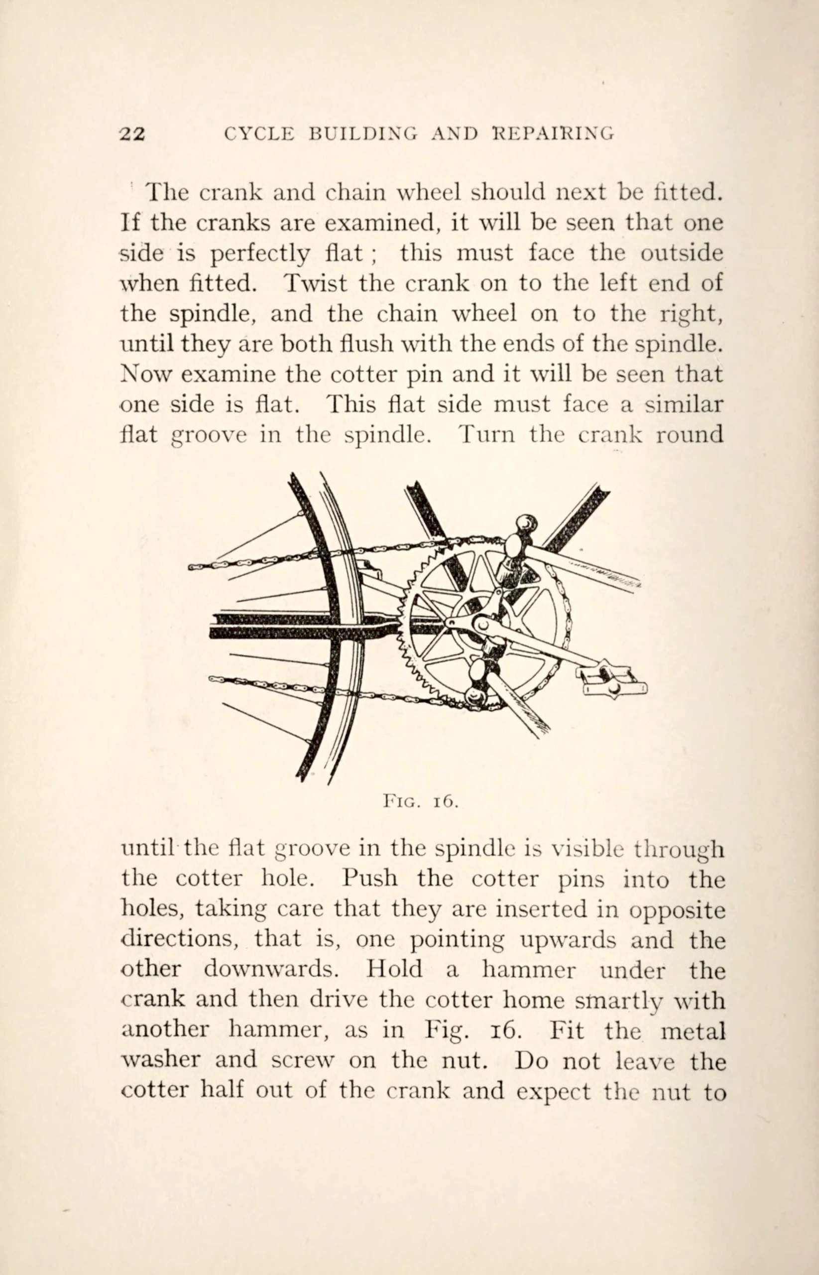
The crank and chain wheel should next be fitted. If the cranks are examined, it will be seen that one side is perfectly flat ; this must face the outside when fitted. Twist the crank on to the left end of the spindle, and the chain wheel on to the right, until they are both flush with the ends of the spindle. Now examine the cotter pin and it will be seen that one side is flat. This flat side must face a similar flat groove in the spindle. Turn the crank round until the flat groove in the spindle is visible through the cotter hole. Push the cotter pins into the holes, taking care that they are inserted in opposite directions, that is, one pointing upwards and the other downwards. Hold a hammer under the crank and then drive the cotter home smartly with another hammer, as in Fig. 16. Fit the metal washer and screw on the nut. Do not leave the cotter half out of the crank and expect the nut to
Fig. 16.
[A line drawing, Fig. 16, of a crank, chain wheel and chain at the rear wheel with a hammer held under the crank to drive in a cotter pin, set in the middle of a paragraph about fitting the crank.]
— Page 27 —
BUILDING A MACHINE 23
draw it into place. The cranks should fit tightly to the spindle.
The pedals are usually marked with an L on one, and an R on the other ; this indicates the left and the right, so put the pedals on accordingly, the former having a left-handed thread and the latter a right-handed thread. It is not essential to fit the pedals at this stage of the work ; they can, if desired, be fitted last. The mudguards, if of the steel variety, should next be fitted ; if the detachable celluloid kind, they may be left until the wheels are fitted. The front guard should be connected to the crown with a bolt and nut, the bolt passing from the front to the back through a hole drilled in the crown. If a hole is not provided, one should be drilled before fitting the forks. The back guard will probably require two holes punched in it, to enable it to be connected to the bridge pieces with nuts and bolts. The front and back stays should next be fitted to the guards. When fitting the screws see that they are inserted in the best position, that is, where the screwdriver can be most easily used. The frame should now be left for a few minutes while the wheels receive attention. To fit a freewheel screw it on the hub as tightly as possible, then wrap a piece of old chain round the cogs for protection, and place it in the vice in a horizontal position. The wheel should then be turned until it is screwed on tightly. It will be advisable to take a file and go round the bed of both rims, so as to file off the tops of any spokes that may pro-
[A full page of text with no illustration, about fitting the pedals, mudguards, stays and a freewheel; the last word is broken by a hyphen at the foot of the page.]
— Page 28 —
24 CYCLE BUILDING AND REPAIRING
trude, as the sharp ends often work through the tapes and cause punctures. Rim tapes should then be fitted in the bed of the rim. Place one side of the outer cover on the rim and then sprinkle the inside liberally with French chalk. The valve should then be placed through the hole in the rim ; adjust the nuts and slightly inflate the tube so as to prevent it getting nipped when the cover is being put on. The subject of tyre fitting is fully described in a chapter on ” Tyre Repairing.” The tyres should be inflated hard before attempting to fit the wheels to the frame. To fit the front wheel see that the adjusting cone is on the left side, and place the spindle through the hole at the bottom of the fork blade. The other blade must now be pulled, so as to increase the distance between the blades, to enable the other end of the spindle to be inserted in the hole. Care must be taken, or the fingers will get damaged between the spokes and the blades. Place the ring, at the bottom of the mudguard stays, on the spindle, or if detachable guards are to be used, fit the plates and screw on the nuts. It will hardly be necessary to provide washers, as the stays will answer the same purpose. The adjusting cone should now be screwed up tight, and then slackened back about half a turn. Hold the wheel so that it is central in the forks and tighten the nuts ; sometimes this tightening causes the adjustment of the hub to be altered.
Now give the wheel the following tests, and if it answers to each of them the wheel is correctly
[A full page of text with no illustration, about fitting rim tapes, the tire cover and the front wheel; the paragraph at the foot continues beyond the page.]
— Page 29 —
BUILDING A MACHINE 25
adjusted. Hold the rim near the forks and try and move it sideways by gently shaking; any looseness will quickly be apparent. If this is the case, loosen the nuts and tighten the adjusting cone a little, then readjust the nuts. Now spin the wheel; it should revolve freely and silently, and when it is about to stop, the weight of the valve should cause the wheel to revolve in the opposite direction. If it stops abruptly, it is obvious that the bearings are too tight and must be slackened a little. After this, it will be advisable to repeat the former test to see if it is still satisfactory.
The back wheel must now be taken in hand ; put the chain adjuster on the spindle, and slip the wheel as far as possible in the slots in the fork ends. It should be noticed that the free wheel is on the same side as the chain wheel, also that the adjusters are between the wheel and the frame. Then fit the mudguard stays and nuts. Try the chain in position to see whether it is necessary to remove or add a link. Full instructions on shortening and lengthening a chain are given on p. 49. If it is the correct length, connect the chain with the nut and bolt ; it is advisable to do this on the chain wheel, as more pressure can be applied with the screwdriver. To adjust the back wheel, tighten the spindle nut on the opposite side of the chain, then tighten the chain adjuster on the chain side, until the chain is just slack ; hold the rim in the centre of the frame with the left hand and tighten the spindle nut with the right. Now loosen the
[A full page of text with no illustration, about testing the front wheel and fitting and adjusting the back wheel and chain.]
— Page 30 —
26 CYCLE BUILDING AND REPAIRING
other spindle nut and tighten the chain adjuster on that side, so that both are equal. Make sure that the rim is still in the centre of the frame, and screw the nut up tightly. The adjustment should now be tested as described above. See also if both wheels are in ” track,” that is, in a perfectly straight line. To test, place a straight edge across the wheels—it should touch the rims in four places.
The handlebar and seat pillar should next be fitted ; there must be at least 2 in. of the stem in the machine, as it is dangerous to ride with less. To facilitate adjustment, smear a little vaseline or oil on the stems ; this often saves a lot of unnecessary straining and pulling in raising or lowering the bar, besides preventing the formation of rust.
To fit a Bowden brake, or brakes of a similar description, first place the handlebar lever in position. This will depend on individual taste, and the majority of cyclists prefer the lever just under the handlebars, so the writer advises that the lever is first fitted in this position and then altered as required.
The bridge and spring clips should next be fitted on the back stays. The former above the tyre and the latter below. Before the shoe can be fitted one of the pad holders must first be removed to allow it to be placed over the back wheel. This is removed by unscrewing the nut which connects it to the shoe. With the older pattern shoe there is no need to remove the pad holder, as the shoe is made in two pieces, which can be taken apart by
[A full page of text with no illustration, about finishing the back wheel adjustment, fitting the handlebar and seat pillar, and fitting a Bowden brake.]
— Page 31 —
BUILDING A MACHINE 27
removing the screws at the top of the shoe. It is also necessary to take the shoe apart to fit the cable. Attach the two springs to the clips and the shoe, now pull the bridge up the stays until the blocks touch the rim, and tighten the nuts and bolts. Pull the spring clips down the stays, which in turn will pull the shoe down, until the wheel is just able to revolve without touching the blocks. When the clip is in position, tighten the nut and bolt to prevent it from slipping. Grip the handlebar lever and see if it locks the wheel; if not, loosen and raise the bridge a little. When the brake works satisfactorily, go over all the nuts and bolts and see that they are screwed up tight. Finally, fit the cable bands to the frame and the handlebars.
With the ordinary type of rim brake the handlebar clip is either fitted to the top or the stem of the bar. To save taking the clip to pieces when fitting, slide it round from the end of the bar (if the grips are not attached) or up the stem. When the pad or block holders are not detachable the shoe must be sprung over the tyre. This is usually the case with the cheaper kind of brakes, but it is advisable to leave them alone, as the fittings are made from such soft material which quickly snaps, besides being very dangerous. The brake must be adjusted so that the blocks are not more than ⅛ in. away from the rim; this gives increased braking power. The adjustment of a back brake, fitted under the chain stays, is usually made by tightening a nut
[A page of text headed Building a Machine on fitting and adjusting a rim brake, with no illustrations.]
— Page 32 —
28 CYCLE BUILDING AND REPAIRING
underneath the bottom bracket, which in turn pulls the shoe and blocks nearer the rim. Or else, there is a nut on the draw-bolt which is unscrewed to make the necessary adjustment. In this case, it is necessary to knock or pull the shoe nearer the rim, and hold it in position and re-tighten the nuts. Should the brake block knock the valve, while the wheel is revolving, it will be necessary to cut away a portion of the block with a sharp knife.
To fit the saddle to the seat pillar, loosen the nuts of the clip, underneath the leather, and twist it on the pillar. The correct tilt of the saddle cannot be advised upon, as it varies with riders. The majority of cyclists prefer the peak of the saddle tilted slightly up, so first try it in this position and alter to suit personal requirements. Screw the clip nuts up very tightly or the tilt of the saddle will alter when mounted and destroy the serrations of the clip. The handlebar grips should next be fixed. Usually it is sufficient to fill them, if new, with boiling water and immediately turn the contents out and place the grip on the bar. Do not attempt to hold or pull the grips until the adhesive has securely set. As an alternative method, the ends of the bars may be heated, taking care not to injure the plating, and a little solid tyre cement smeared on the bar; the grips should then be fitted and left until they are securely fixed. The writer has always found the former method quite satisfactory, and it is certainly less trouble. When fitting the pump clips a little discretion should be used as to which
[A page of text with the running head Cycle Building and Repairing on adjusting a back brake, fitting the saddle and fixing the handlebar grips, with no illustrations.]
— Page 33 —
BUILDING A MACHINE 29
tube they should be attached. The top tube is not very suitable, as the pump is in the way when lifting the machine. The objection to the down tube is that the pump is not visible when riding. So it is advised that the pump be fitted to the tube from the head to the bottom bracket, as by so doing the pump is always visible, and at the same time is out of the way. The bell and the toe-clips (if any) should then be fitted, and the machine, if a gentleman’s, will be complete.
The handlebars of a lady’s machine should be raised so that they are a little higher than the saddle. The dress guard should be provided with detachable quadrants which are attached to the back stays. It is not necessary to describe the fitting of the dress guard, as it is so exceedingly simple. To fit a celluloid variety chain cover, attach the support for the frame behind the chain wheel, on the chain stays, with two screws. Then place the pedal and the chain wheel crank through the circular hole provided in the cover. The projecting piece of metal, on the top of the support, is placed through the hole in the frame of the cover; the bottom portion of the support being fixed to the frame with a screw. The support at the freewheel end of the cover is usually riveted to the frame and is fixed to the stays by means of a clip screwed to the support. Before tightening the screw, turn the crank and the chain round and see if they knock the cover at any place. If they should knock at any place, it will be necessary to
[A page of text headed Building a Machine on fitting the pump, bell and toe clips, the lady’s machine dress guard and a celluloid chain cover, with no illustrations.]
— Page 34 —
30 CYCLE BUILDING AND REPAIRING
alter the position of the cover. The metal case for protecting the freewheel should next be fitted. This may be attached by just sliding the case over the end of the frame, telescopic fashion, or by screwing together with nuts and bolts. The former method is quite satisfactory, and it certainly saves time when removing the wheel.
The machine should now be given a thorough lubricating, and it will be ready for the owner to ride just where he pleases without the slightest fear of the machine failing. Do not forget to close all the lubricating holes with the respective caps, or dust will get in the bearings.
[A page with the running head Cycle Building and Repairing holding two short paragraphs on fitting the freewheel case and lubricating the finished machine, with the rest of the page blank.]
— Page 35 —
CHAPTER III
BUILDING THE WHEELS
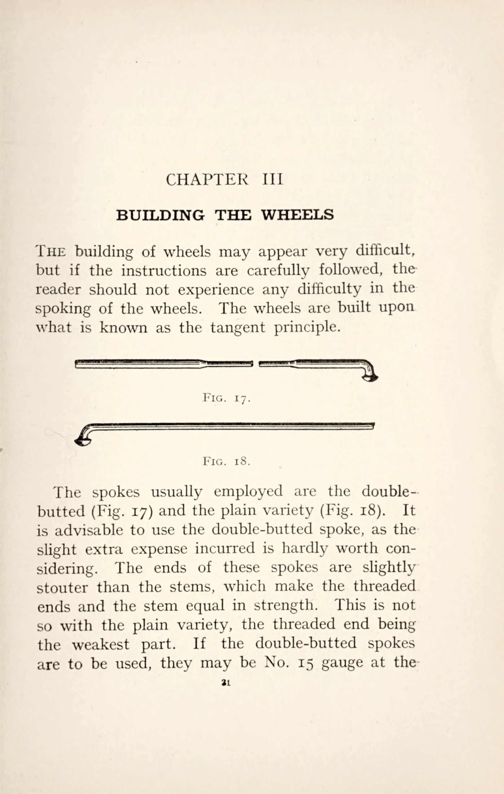
The building of wheels may appear very difficult, but if the instructions are carefully followed, the reader should not experience any difficulty in the spoking of the wheels. The wheels are built upon what is known as the tangent principle.
Fig. 17.
Fig. 18.
The spokes usually employed are the double-butted (Fig. 17) and the plain variety (Fig. 18). It is advisable to use the double-butted spoke, as the slight extra expense incurred is hardly worth considering. The ends of these spokes are slightly stouter than the stems, which make the threaded ends and the stem equal in strength. This is not so with the plain variety, the threaded end being the weakest part. If the double-butted spokes are to be used, they may be No. 15 gauge at the
31
[Opening of Chapter III, Building the Wheels, with two drawings of single spokes with bent heads, captioned Fig. 17 and Fig. 18, and a page number at the foot.]
— Page 36 —
32 CYCLE BUILDING AND REPAIRING
ends and No. 18 gauge at the stem. However, if it is desired to use the plain variety spoke, a suitable gauge will be No. 16. The spokes should be purchased all ready threaded and cut to a size, as special tools would be required which would not pay the amateur to possess, if only a few pairs of wheels are to be built. It will also be advisable to obtain the rims drilled, as it will save an immense amount of trouble. If it is desired to drill the rims, the spoke holes must first be set out in the rim; there will be thirty-two required for the front wheel and forty for the back wheel. There are two simple methods of setting out the spoke holes. Firstly, place a piece of string round the inside of the rim, so as to ascertain the exact length. This distance should then be measured, and the result obtained, divided by thirty-two or forty, whichever wheel it is intended for. A pair of dividers should then be set to this measure. Now step round the rim the exact number of times and mark each point with a piece of chalk.
The second method, and probably the simpler of the two, is to obtain a wheel ready built to act as a guide and place the rim upon this and carefully mark the position for the spoke holes. If the spoke holes are examined in the guide rim, it will be noticed that they are not all drilled on a centre line, but alternately on each side of a centre line. This enables the spokes to have a greater pull on the rim. The holes must not be more than 1/16 in. on each side of the line. To facilitate this, it will
[A page of text with the running head Cycle Building and Repairing on gauges of spokes and on setting out the spoke holes in a rim, with no illustrations.]
— Page 37 —
BUILDING THE WHEELS 33
be advisable to draw or scratch two lines, about ⅛ in. apart, round the rim with a marking gauge, and centre punch the position for the spoke holes. When using the punch, the rims should be supported on a padded surface, consisting of old pieces of cloth material placed on the end of the vice. The blows should be delivered gentle and sharp, or the rim will be damaged. The rims are now ready for drilling, which can be best accomplished in the lathe. Care must be taken to get the valve hole centrally between two spoke holes. The holes should then be filed to remove any roughness which has been left from drilling.
When spoking the wheels it is a good plan, especially for the amateur, to number the holes in the rim. This can easily be accomplished by sticking small pieces of gum paper, such as stamp edging, against each hole, and numbering them in numerical order. If the holes in the hub flange are examined, it will be seen that they are countersunk alternately on each side of the flange; this enables the round heads of the spokes to be slightly embedded.
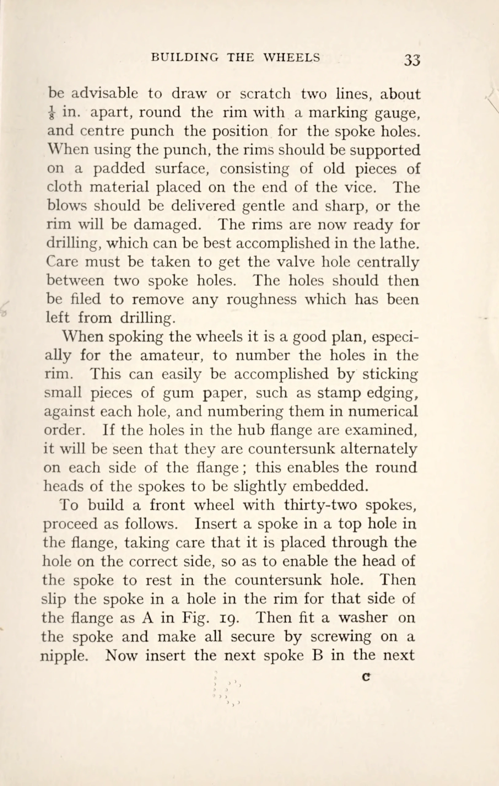
To build a front wheel with thirty-two spokes, proceed as follows. Insert a spoke in a top hole in the flange, taking care that it is placed through the hole on the correct side, so as to enable the head of the spoke to rest in the countersunk hole. Then slip the spoke in a hole in the rim for that side of the flange as A in Fig. 19. Then fit a washer on the spoke and make all secure by screwing on a nipple. Now insert the next spoke B in the next
[A page of text headed Building the Wheels on marking out and drilling the rim and on starting to spoke a front wheel, with a printer’s signature letter at the foot, a faint pencil squiggle in the left margin, a crease at the top right edge and a small group of punched holes near the bottom center.]
— Page 38 —
34 CYCLE BUILDING AND REPAIRING
hole on the other side of the same flange. Cross the spoke B over A and place it through a hole in the rim so as to leave nine holes between the spokes. Fit the next spoke C in the seventh hole in the flange, and place it through a hole in the rim so as to leave
Callouts: J E A B I F H D C G
Fig. 19.
five holes between spokes B and C. Fit the next spoke D in the eighth hole in the flange, and connect to a hole in the rim so as to leave nine rim holes between spokes C and D. This should also leave five holes between A and D. It is essential that the heads of the spokes should rest in the countersunk holes, so make sure that they are all inserted from
[A line drawing, Fig. 19, of a wheel rim with a hub flange and 10 lettered spokes crossing from the flange to the rim, set between paragraphs of text under the running head Cycle Building and Repairing; a crease at the top left edge and a small group of punched holes near the bottom center.]
— Page 39 —
BUILDING THE WHEELS 35
the correct side before proceeding with the work. Turn the wheel over, then fit four more spokes, E, F, G, H, in exactly the same way on the opposite side of the flange. The spokes should be inserted in the flange holes directly opposite the spokes on the other end of the flange. The nipples should be screwed on the spokes until they are just taut. Turn the wheel round again, and insert the remainder of the spokes on that side of the flange. The letter references I and J show the position for the next pair of spokes; there must be nine holes between them. Every alternate spoke inserted in the flange, when connected to the rim, should have three rim holes between. The remainder of the spokes are fitted in exactly the same way. The spokes with their heads embedded on the outside of the flange must cross on the outside those with their heads on the inside. The spokes should now be tightened equally with a nipple key or a ratchet screwdriver, taking care that the rim is not pulled out of shape. Instructions on truing a wheel will be found on p. 40.
To build a wheel containing forty spokes, proceed as follows:—
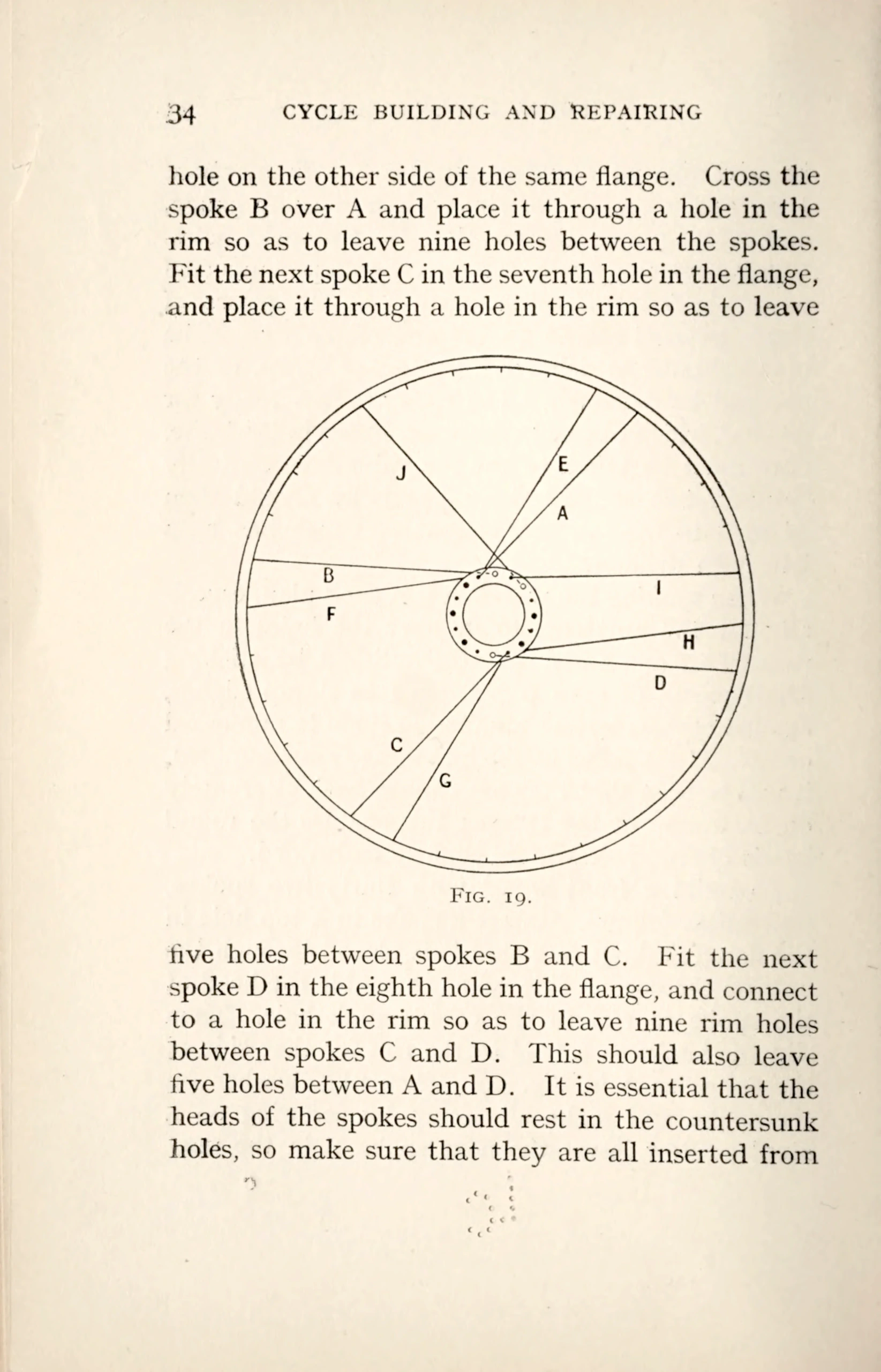
Insert a spoke through a flange hole and then put it through a hole in the rim as A in Fig. 20. A washer should then be fitted and a nipple screwed on the spoke, just sufficient to hold it in position. The spoke B should be inserted in the seventh flange hole from A. The holes should be counted in the same direction as the hands travel
[A page of text headed Building the Wheels on spoking a front wheel with 32 spokes and starting a wheel with 40 spokes, with no illustrations and a small dark speck in the left margin.]
— Page 40 —
36 CYCLE BUILDING AND REPAIRING
in a clock. The spoke should then be crossed over or under A (this being decided as explained in a previous paragraph) and then connect to the rim two holes above A. The spoke C should be inserted in the third flange hole from B ; this should be connected to the rim, so as to leave seventeen rim holes between B and C. The spoke D should be inserted in the seventh flange hole from C. This should also leave two holes in the flange between D and A. The spoke should then be crossed over or under C, and connected to the rim, two holes below. The spokes should now be checked to see if they
Fig. 20.
Callouts: A B C D E F G H
[Fig. 20, a line drawing of a wheel rim and hub flange with eight spokes lettered A to H, set between two blocks of text on spoke lacing. The text runs across the figure as one sentence.]
— Page 41 —
BUILDING THE WHEELS 37
are correct, before proceeding with the building. Having satisfied yourself on this point, place spoke E through the second flange hole from A and connect to the rim so as to leave three rim holes between A and E. In every other flange hole insert a spoke, and connect it to the rim so as to leave three rim holes between it and its predecessor. A glance at the spokes F and G will make this quite clear. It will also be observed that the spokes B and G form the first pair, and if the instructions have been carried out, it should leave thirteen rim holes between. Insert five more spokes as described above to complete the spokes running in the same direction. Place the spoke H in the flange hole between A and E, and cross over A and connect to a rim hole, so as to leave thirteen holes between. Then insert the remainder of the spokes to fill the vacant holes on that end of the flange. It must be remembered that the spokes when connected to the rim must have three holes between. Care must also be taken to cross the spokes correctly. Should any be found incorrect, unscrew the nipple and remedy the error. This will complete the lacing of the spokes on this end of the flange. Turn the wheel round and place a spoke straight through a hole in the flange (in a parallel line with the hub), it will point between two spokes in position. These spokes will have been inserted from opposite sides of the flange, and the one that has been fitted from the inside of the flange will act as the guide for the remainder of the spokes. Pull the spoke up to
[A page of continuous text under the running head Building the Wheels, with no figures, giving directions for lacing spokes through the hub flange. The last words of the final line are lightly worn in the print.]
— Page 42 —
38 CYCLE BUILDING AND REPAIRING
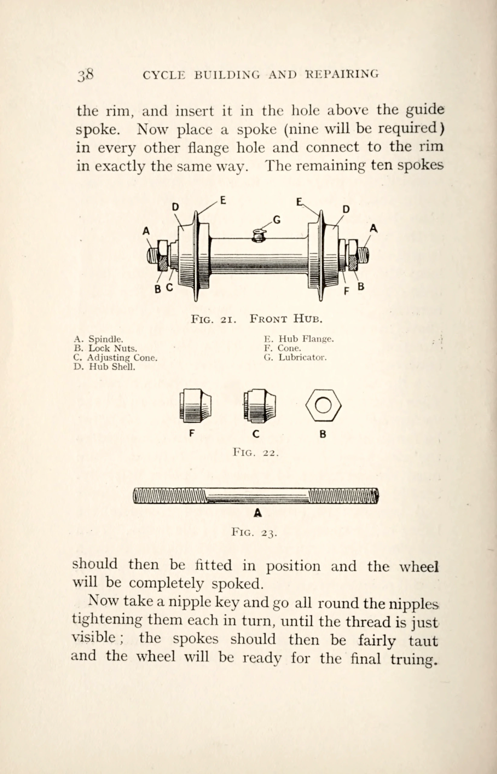
the rim, and insert it in the hole above the guide spoke. Now place a spoke (nine will be required) in every other flange hole and connect to the rim in exactly the same way. The remaining ten spokes should then be fitted in position and the wheel will be completely spoked.
Now take a nipple key and go all round the nipples tightening them each in turn, until the thread is just visible ; the spokes should then be fairly taut and the wheel will be ready for the final truing.
Fig. 21. Front Hub.
Callouts: A B C D E F G
A. Spindle.
B. Lock Nuts.
C. Adjusting Cone.
D. Hub Shell.
E. Hub Flange.
F. Cone.
G. Lubricator.
Fig. 22.
Callouts: F C B
Fig. 23.
Callouts: A
[Three engraved figures with lettered parts: a front hub with its spindle, lock nuts and flanges, then a cone, an adjusting cone and a hexagonal lock nut, then a threaded spindle. The text of the page runs across the figures as one sentence.]
— Page 43 —
BUILDING THE WHEELS 39
If a wheel building stand is not available, the frame of the cycle will be suitable for the purpose. Instructions on truing a wheel will be found on p. 40.
The wheels will always be a continual source of worry if the correct tension is not obtained on all the spokes, so care must be taken in the truing of the wheels.
[A short page of two paragraphs under the running head Building the Wheels, with the lower four fifths of the page left blank and no figures.]
— Page 44 —
CHAPTER IV
SIMPLE REPAIRS
It will be advisable for the reader to make himself thoroughly acquainted with the various repairs described in this chapter, as it may be the means of saving many a shilling, besides having the satisfaction of accomplishing it himself. Then again there is another point from which it may be looked at with advantage, the accident on a country road, which may result in a long, weary walk to the nearest cycle repairer, before the journey can be resumed. We ask the reader, whether it would not be better to open the tool bag and make good the damage on the spot ?
The repairs described will be found exceedingly simple, and can be undertaken by anybody possessing a few tools, a little dexterity with the fingers, and last, but not least, a little patience. A frequent repair in the workshop is a wheel out of truth. First remove the wheel and then take the tyre off. Now slip the wheel back in the frame and tighten up both the nuts. Give the wheel a good spin and hold a piece of chalk by the forks to one side of the rim ; this will mark any places that are out of truth.
40
[The opening page of Chapter IV, Simple Repairs, with the chapter heading in the middle of the page below a wide blank upper margin and the page number printed at the foot. Faint show-through of the reverse side’s text is visible in the upper margin.]
— Page 45 —
SIMPLE REPAIRS 41
Stop the wheel, and note where there are any chalk marks. Get the nipple key and gradually tighten the spokes opposite the chalk marks that are connected to the other side of the hub. Now hold the chalk to the other side of the rim and tighten up the spokes in the same way. By chalking and tightening alternately on each side of the rim the wheel will become dead true. Take a file and go round the inside of the rim and file off the tops of any spokes that may protrude through the nipples.
To true a wheel that is out of truth in the round, spin it and hold a piece of chalk to the top of the rim so that it marks any high places. Now gradually tighten the spokes on both sides under the chalk marks. Hold a rule or anything having a flat edge up against the forks so that the wheel will just clear it when revolving. This will show up any low places that may be in the rim, and the spokes should be loosened at all such places.
Should any spokes be broken they can be replaced very cheaply. Make sure what size the wheel is ; if uncertain look at the outer cover and see what size is stamped round the edge. A cycle repairer will supply a new spoke and nipple the size required for twopence. Should more than one be broken, do not take them all out at once, otherwise it might not be quite clear to which hole in the rim the new spoke should be connected.
Slip the spoke through the hole in the hub flange and place the nipple through the rim and connect up by screwing the nipple on the spoke and tighten
[A page of continuous text under the running head Simple Repairs, with no figures, giving directions for truing a wheel and replacing broken spokes.]
— Page 46 —
42 CYCLE BUILDING AND REPAIRING
up with a nipple key. The wheel is then trued as described above.
Should there be any clicking noise in the wheels it is probably caused by a broken ball, or the cones may have become the worse for wear. It is of no use guessing the cause of the noise ; loosen the adjusting cone, C in Fig. 21, and hold the wheel on the slant, so that the balls will fall out into the hand. Then place the balls in a box, eggcup, or other suitable receptacle, so that they will not get knocked over and scattered all over the floor, as experience has taught that they are very difficult to find again. Remove the cones C and F and take out the spindle A. Soak a piece of rag in paraffin and pull it backwards and forwards through the hub shell D, to clean it, then rub the cones and spindle with the rag. To clean the balls, place them in a rag and rub briskly between the hands. Now examine each one carefully, and should any be damaged throw them away. Do not trust to remembering the size of the balls when purchasing new ones, but take a sample to the shop. The cones and cups of the hub will also require examining, and if damaged they will have to be replaced.
When replacing the balls get some vaseline and smear the cups. Count the balls and place half of them in the cup ; screw the cone on to the spindle and put it through the hub. Be careful not to knock any balls down between the spindle and the hub shell. Hold the spindle tightly, so as to prevent the balls from tumbling out, and lay the
[A page of continuous text under the running head Cycle Building and Repairing, with no figures, on clicking noises in wheel hubs and the cleaning and refitting of hub balls and cones.]
— Page 47 —
SIMPLE REPAIRS 43
wheel carefully over on its side, to enable the remaining balls to be replaced. Then screw the adjusting cone up tight, then slacken back half a turn so that there is just sufficient play. Hold the wheel in the hands by the spindle, and give the spokes a sharp twist with the thumb ; it should revolve freely, that is, if the cone has been properly adjusted.
When removing cotter pins from the cranks it is always attempted with risks of damaging the machine unless a cotter pin extractor is used. If one is not possessed, it must be done very carefully with a hammer. Remove the nut and washer from the cotter, hold a hammer under the crank so as to reduce the shock the machine will receive and knock the cotter out with another hammer, as shown in Fig. 16 on p. 22. Hit the cotter squarely, taking care not to burr over the thread. The crank can now be easily removed. It will be found when replacing cotters that it is much easier to remove them than to replace them.
After an accident, it is often found that the crank is bent ; sometimes it is so bad that it will not revolve without knocking the sides of the frame. If so, hold the machine rigid and try and force the crank by pressing with the foot. It can generally be bent sufficiently in this way to complete the journey.
When the destination is reached, the crank should be removed and straightened properly. Wrap it in a piece of rag to protect the plating, lay a piece
[A page of continuous text under the running head Simple Repairs, with no figures, on removing cotter pins from cranks and straightening a bent crank.]
— Page 48 —
44 CYCLE BUILDING AND REPAIRING
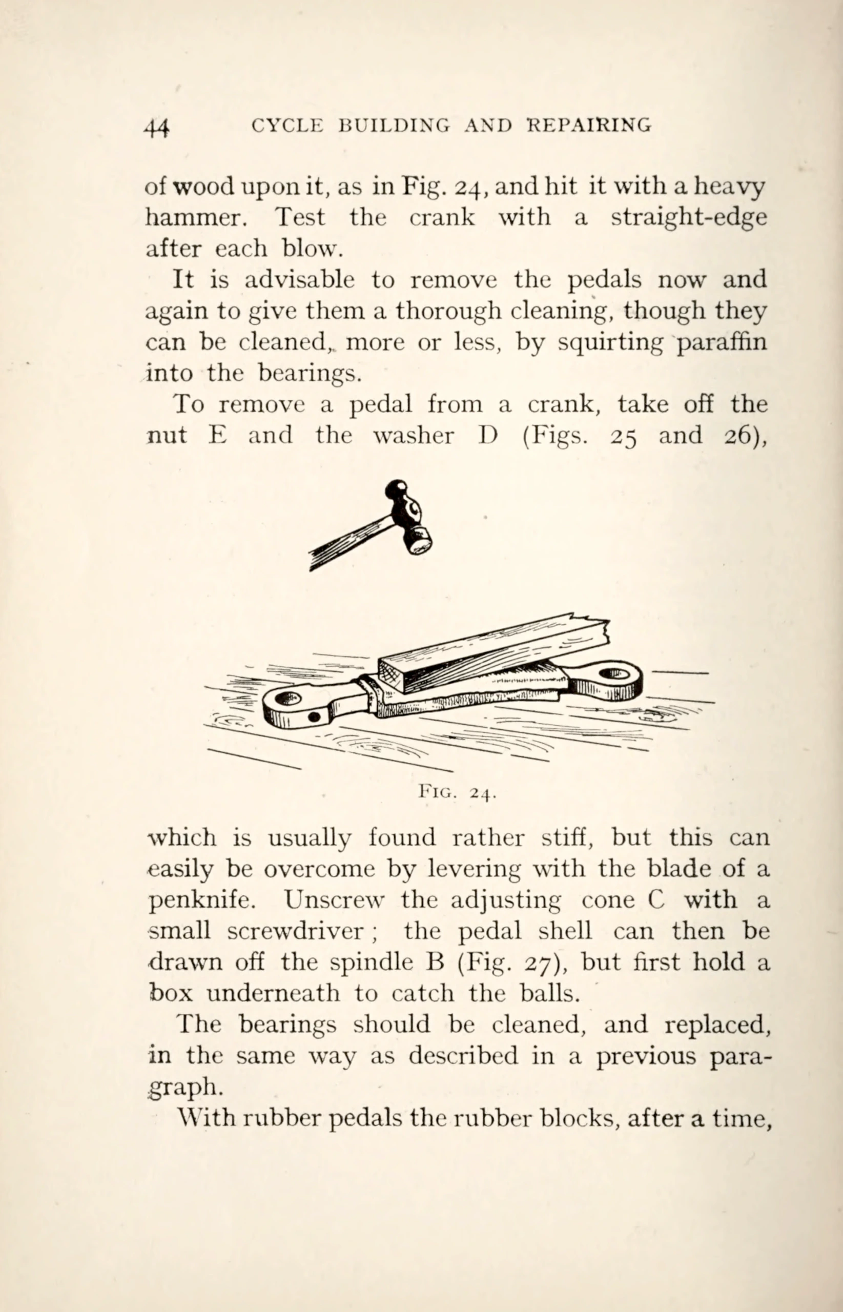
of wood upon it, as in Fig. 24, and hit it with a heavy hammer. Test the crank with a straight-edge after each blow.
It is advisable to remove the pedals now and again to give them a thorough cleaning, though they can be cleaned, more or less, by squirting paraffin into the bearings.
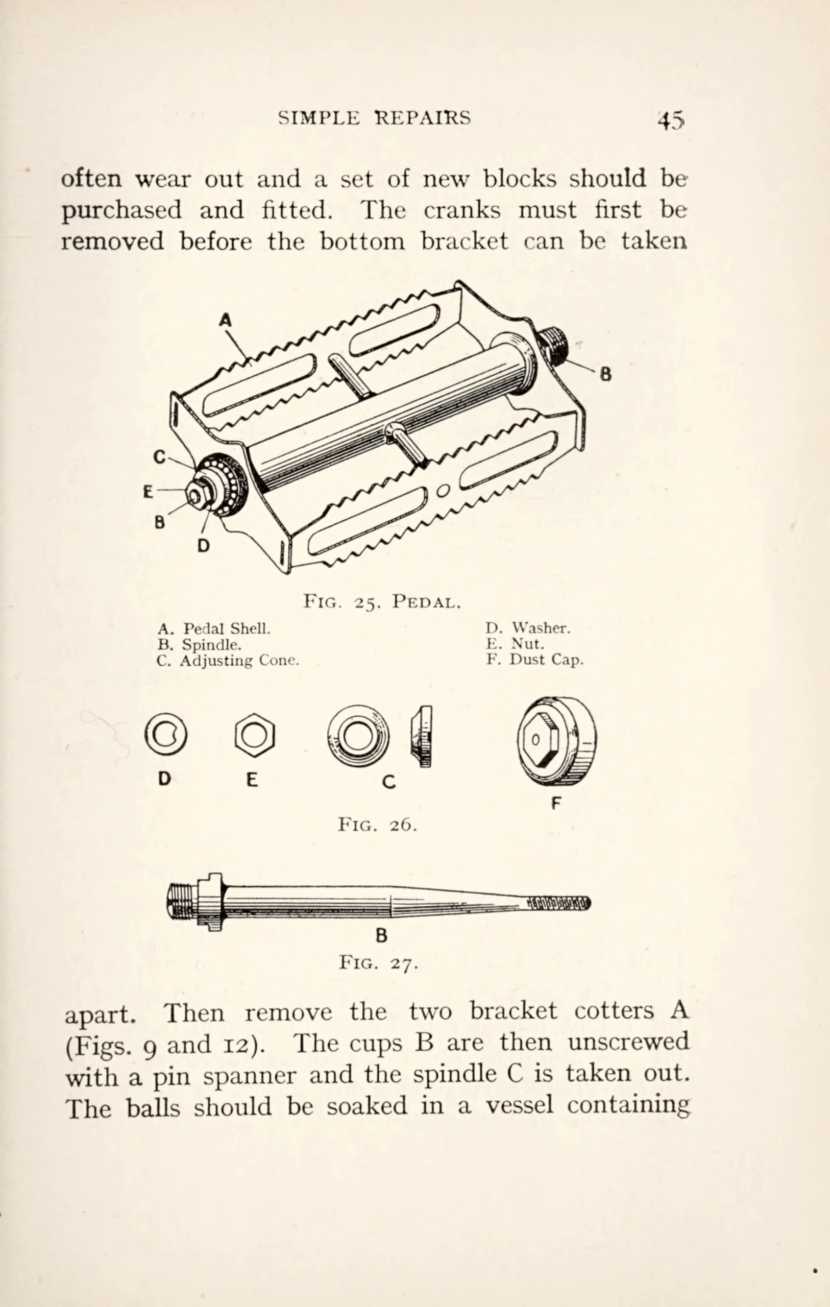
To remove a pedal from a crank, take off the nut E and the washer D (Figs. 25 and 26), which is usually found rather stiff, but this can easily be overcome by levering with the blade of a penknife. Unscrew the adjusting cone C with a small screwdriver ; the pedal shell can then be drawn off the spindle B (Fig. 27), but first hold a box underneath to catch the balls.
The bearings should be cleaned, and replaced, in the same way as described in a previous paragraph.
With rubber pedals the rubber blocks, after a time,
Fig. 24.
[Fig. 24, a line drawing of a bent crank lying on a bench with a strip of wood across it and a hammer raised above, set between two blocks of text on straightening a crank and removing pedals. The text runs across the figure as one sentence.]
— Page 49 —
SIMPLE REPAIRS 45
often wear out and a set of new blocks should be purchased and fitted. The cranks must first be removed before the bottom bracket can be taken apart. Then remove the two bracket cotters A (Figs. 9 and 12). The cups B are then unscrewed with a pin spanner and the spindle C is taken out. The balls should be soaked in a vessel containing
Callouts: A B C E B D
Fig. 25. Pedal.
A. Pedal Shell.
B. Spindle.
C. Adjusting Cone.
D. Washer.
E. Nut.
F. Dust Cap.
Callouts: D E C F
Fig. 26.
Callouts: B
Fig. 27.
[A bicycle pedal drawn whole as Fig. 25, with a lettered key to its pedal shell, spindle, adjusting cone, washer, nut and dust cap, then the washer, nut, cone and dust cap drawn singly as Fig. 26 and the spindle as Fig. 27. The text above and below the drawings is the continuation of a paragraph on taking the bottom bracket apart.]
— Page 50 —
46 CYCLE BUILDING AND REPAIRING
paraffin oil to clean them. The bracket is cleaned by passing a rag dipped in paraffin oil backwards and forwards. Full instructions on fitting the bracket together will be found on p. 19.
To remove the front forks first unscrew the headlock nut A, in Fig. 13, and disconnect the brakes. The handlebars can then be removed. The headlock ring, B, is then unscrewed with a pin spanner. Extreme care must be used now, otherwise the balls will fall out. Hold the crown of the forks and the frame with one hand, pull the headlock, C, off with a twist and upward motion with the other. The balls will now be exposed; they should be placed in an eggcup or any suitable receptacle. Now carefully lift the frame from the forks. Hold the frame at an angle, and place the hand underneath the crown to catch the balls, and pull the forks a little out of the frame.
When it is desired to fix a freewheel the old fixed cog or freewheel, whichever is fitted, must first be removed.
With the fixed cog there is a lock ring, which can be unscrewed with a punch and a hammer. This ring unscrews to the right, as it has a left-handed thread. The cog wheel can be removed by placing it in the vice and turning the wheel round to the left. In the absence of a vice, place the wheel in the frame, adjust the chain and tighten both nuts on the spindle. Hold the machine so that the wheel cannot revolve and turn the chain backwards by means of the pedals.
[A page of text only, on removing the front forks and taking off the fixed cog or freewheel with its lock ring.]
— Page 51 —
SIMPLE REPAIRS 47
A freewheel can be removed with a punch and a hammer. They are usually very stiff, so a heavy blow must be given with the hammer. It will be as well when buying a freewheel to take the old wheel to the shop in order to get one the size required. This will save any unnecessary changing.
The freewheel is fitted in the same manner as described above, with the exception that the wheel or chain should be turned in the opposite direction.
It may have been noticed that something has slipped when applying extra pressure to the pedals, such as riding a hill. If so, it is probably the clutch that is at fault. To test a freewheel clutch to see if it is working correctly, turn the freewheel back a little with the pedals, and then press forward. Repeat this for a number of times; if it is working correctly, it should lock every time and not slip. Should it be found to slip it has most likely been over-oiled. Lay the machine over on its side and squirt paraffin liberally in through the oil holes. Turn the freewheel round several times and try the clutch again. It will now most likely be found to work satisfactorily. Do not use a thick oil when lubricating. A little colza with paraffin will be suitable.
As there are now so many different coaster and speed hubs on the market, space will not permit giving instructions on the various adjustments needed. The writer advises any reader who experiences any difficulty, to apply to the manufacturer, who will no doubt be able to supply a descriptive
[A page of text only, on removing and fitting a freewheel, testing and oiling its clutch, and the adjustment of coaster and speed hubs.]
— Page 52 —
48 CYCLE BUILDING AND REPAIRING
pamphlet fully describing the adjustments of the hub.
The best way to clean a chain that is thick with dust and grease is to soak it in a vessel containing paraffin oil for two or three days. If two small pieces of wood are laid at the bottom of the vessel and the chain coiled up on top of these, it will enable the chain to receive a thorough soaking in the oil. Remove the chain and hang it over the vessel to catch the paraffin that will drip off. Wipe the chain dry with a piece of old rag and lubricate it with some chain graphite. A good chain lubricant can be made by powdering some plumbago (blacklead) and mixing it with colza oil until it is of the consistency of treacle. When this is being made, make a supply, as it is not any more trouble to make a quantity than only to make sufficient for one lubrication. It should be kept in a tin box provided with a lid to keep any dirt and dust from mixing with it. An old brush should also be kept for the purpose of applying the lubricant to the chain.
A more thorough method of lubricating a chain is to boil it in some mutton tallow with a little powdered blacklead, then remove the chain and wipe it thoroughly. This is one of the best ways of lubricating a chain, as the tallow gets inside every roller and link. Care should be exercised when melting the tallow, as it is very inflammable.
When fitting the chain to the machine make sure that it is connected together securely. It is
[A page of text only, on cleaning and lubricating a chain with paraffin oil, plumbago and colza oil, or mutton tallow and blacklead, and on fitting it to the machine.]
— Page 53 —
SIMPLE REPAIRS 49
as well to glance at this every now and again and tighten the nut and bolt with a screwdriver, as the nut often works loose, owing to the jolting and vibration of the machine, and if the bolt were to come out whilst riding down a hill, a nasty accident might be the result, especially if a back pedalling brake is used, for there would be no means of applying the brake.
When a chain has been in use for some time, the rivets occasionally work loose. To tighten them, lay the chain on its side on a piece of iron or steel, and hammer the loose rivets with a heavy hammer, until they are burred over and fit tightly.
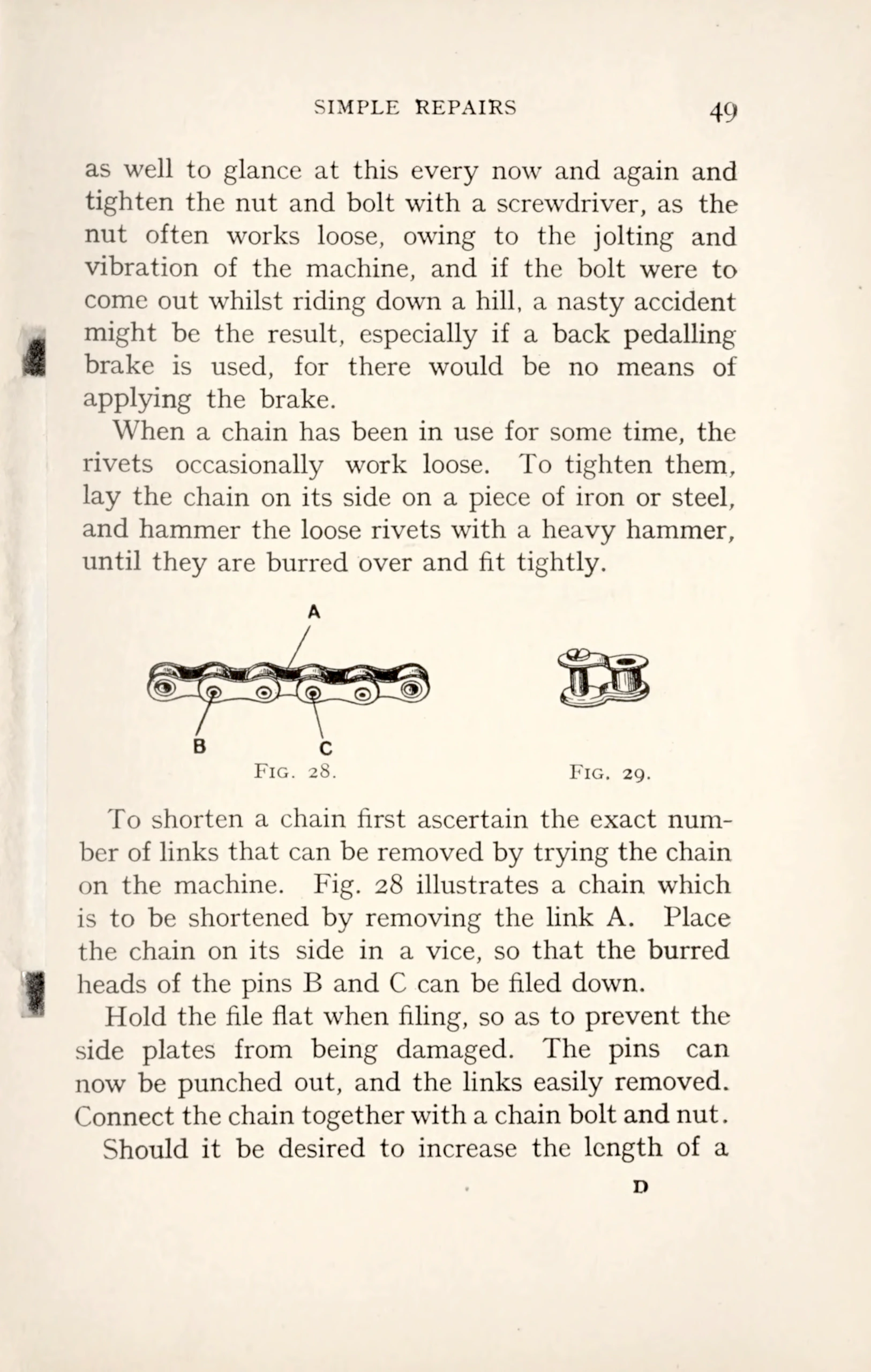
To shorten a chain first ascertain the exact number of links that can be removed by trying the chain on the machine. Fig. 28 illustrates a chain which is to be shortened by removing the link A. Place the chain on its side in a vice, so that the burred heads of the pins B and C can be filed down.
Hold the file flat when filing, so as to prevent the side plates from being damaged. The pins can now be punched out, and the links easily removed. Connect the chain together with a chain bolt and nut.
Should it be desired to increase the length of a
Callouts: A B C
Fig. 28.
Fig. 29.
[A short length of bicycle chain with three points lettered as Fig. 28, and a single chain link with its bolt as Fig. 29, between paragraphs on tightening, shortening and joining a chain. Two small dark speckled patches sit in the left margin and a printer’s signature letter appears at the foot.]
— Page 54 —
50 CYCLE BUILDING AND REPAIRING
chain, special links for the purpose can be bought. If only one link is required in the chain purchase one similar to Fig. 29. When the chain requires adjusting, undo the nut on the chain side, alter the chain adjuster and then tighten up the spindle nut. Treat the nut and chain adjuster on the opposite side in the same way. While tightening the nut hold the wheel in the centre of the frame.
Sometimes when borrowing a machine from a friend, after lowering the seat pillar to its lowest extent, it is found that the frame is too tall. In such a case as this, the saddle clip should be reversed, so that it is above the seat pillar. This will be found to lower the saddle. When raising the seat pillar, see that there is quite 2 in. left in the down tube of the machine, as riding with less is dangerous.
The hardness of a saddle, owing to the leather being stretched too tight, can be remedied by loosening the nut underneath the leather at the peak of the saddle. Or the leather can be softened and made pliable by rubbing the underneath side with a little castor oil. Use the oil sparingly, otherwise it will be liable to stain the trousers.
Never attempt to alter the tilt of a saddle before first loosening the nuts of the saddle clip, or the serrations will be destroyed. The correct tilt of the saddle will depend on the rider, and can only be ascertained by altering and using the saddle. The majority of riders ride with the peak of the saddle tilted up slightly.
[A page of text only, on adjusting a chain, lowering a saddle by reversing its clip, loosening a hard saddle and setting its tilt.]
— Page 55 —
SIMPLE REPAIRS 51
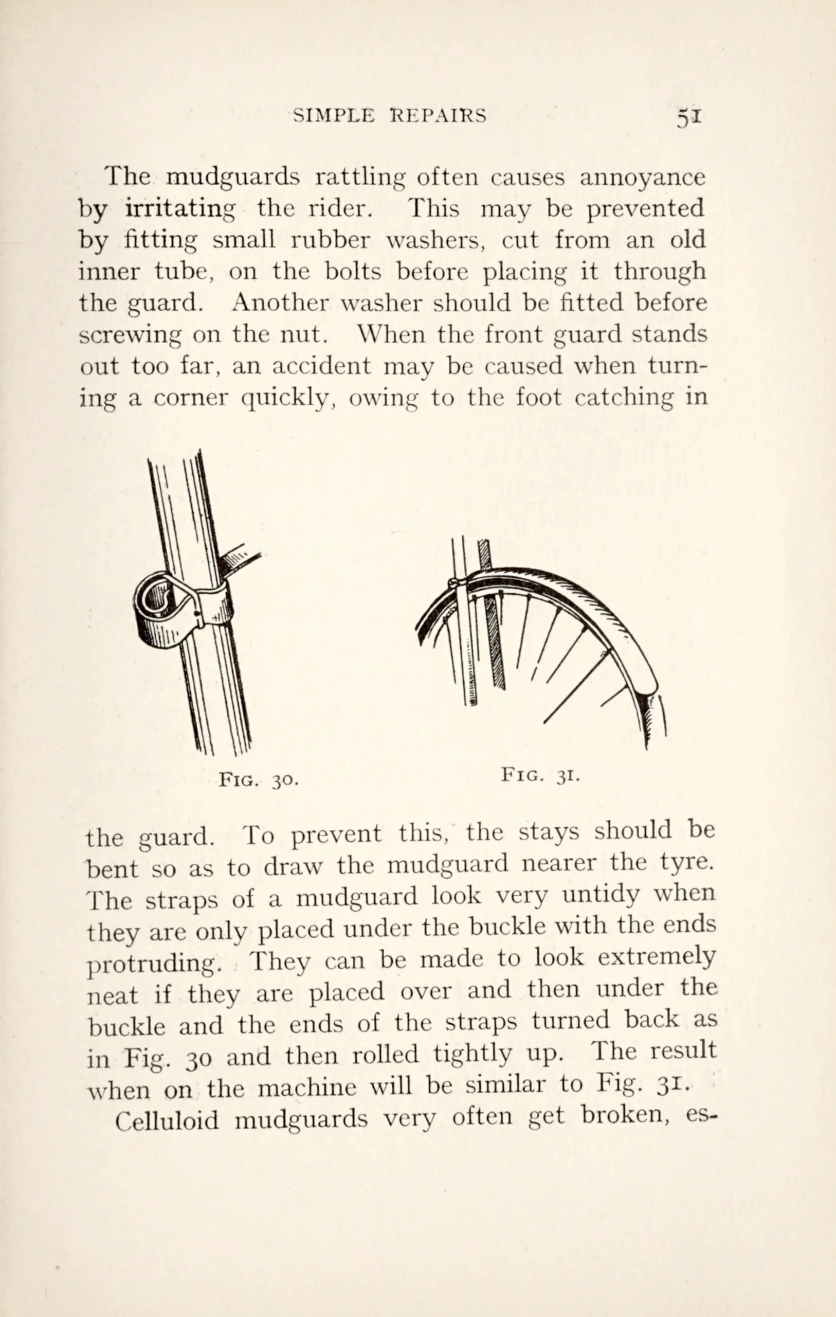
The mudguards rattling often causes annoyance by irritating the rider. This may be prevented by fitting small rubber washers, cut from an old inner tube, on the bolts before placing it through the guard. Another washer should be fitted before screwing on the nut. When the front guard stands out too far, an accident may be caused when turning a corner quickly, owing to the foot catching in the guard. To prevent this, the stays should be bent so as to draw the mudguard nearer the tyre. The straps of a mudguard look very untidy when they are only placed under the buckle with the ends protruding. They can be made to look extremely neat if they are placed over and then under the buckle and the ends of the straps turned back as in Fig. 30 and then rolled tightly up. The result when on the machine will be similar to Fig. 31.
Celluloid mudguards very often get broken, es-
Fig. 30.
Fig. 31.
[A mudguard strap rolled up beside its buckle on a frame tube as Fig. 30, and a front mudguard fitted over a wheel with spokes and fork as Fig. 31, set between paragraphs on mudguards.]
— Page 56 —
52 CYCLE BUILDING AND REPAIRING
pecially the front guard, through the foot catching in it when turning a corner. The best way of dealing with a guard broken in two is to cut a piece from an old guard to form a background, which should be riveted inside the broken guard. Should an old guard not be obtainable, a piece of tin can be employed. The tin, or celluloid, should be cut about 6 in. long and nearly the same width as the guard. Holes must now be drilled in the guard, and in the plate to receive the rivets (about a dozen will be sufficient). If tin is used, it must be treated with a coat of paint or japan on both sides, to prevent the formation of rust. The rivets can be obtained at any tool-dealer’s shop.
The brake blocks of rim brakes should be adjusted so that they are parallel to the wheel, and that it just clears them while revolving. Should the rim knock up against the blocks in certain places, it is evident that the wheel is not true, and before the brakes can be adjusted properly the wheel must be put right.
The brakes will also work with a jerky action if the wheel is out of truth. When the brake blocks are worn, it will be found that the inside of the block is worn more than the outside. If these blocks are reversed, it gives them a new lease of life, as it will bring that part of the block into use that is not worn.
The brakes will spring off the wheel much easier if the stirrups are oiled where they enter the slots in the fork clips.
[A page of text only, on mending a broken celluloid mudguard with a tin or celluloid backing and on adjusting, reversing and oiling rim brake blocks and stirrups.]
— Page 57 —
SIMPLE REPAIRS 53
The nuts and screws of a brake should be constantly tried to see if they are working loose.
The wires of cable brakes after a time occasionally get frayed out at the handlebar lever, and also by the bridge. The cable is generally long enough to allow of it being shortened.
To shorten a cable, heat the brass nipple until the solder melts. Pull the cable through the nipple with a pair of pliers until the damaged portion is passed. Sever the cable and place the nipple in a vice so that about an eighth of an inch protrudes beyond the nipple. Burr the strands of the cable over the head of the nipple with a hammer, and then make all secure with a little solder.
If the cable is not long enough, a new one should be purchased and fitted without delay, as the frayed wires are liable to part any time and the brake would be useless. When fitting a new cable, it must first be well coated with vaseline.
A few words on using the spanner will not be amiss. The first thing is to see that the spanner fits the nuts properly, for if not, the corners of the nuts will soon be rounded and adjustment will be made difficult, owing to the spanner slipping. Should a screw-hammer be used, see that it is screwed up tightly on the nut for the reason stated above.
When tightening a nut, do not overdo it, as it is possible to damage the thread. Do not think by this that riding with the nuts loose is advocated; there is reason in everything.
See that there is plenty of room for the knuckles
[A page of text only, on checking brake nuts and screws, shortening a brake cable at its brass nipple with solder, and on using a spanner.]
— Page 58 —
54 CYCLE BUILDING AND REPAIRING
should the nut or spanner slip. More pressure can be brought to bear on the nuts if the spanner is so held that part of the machine can be grasped by the hand.
When the sides of a nut become rounded, and sufficient force cannot be used to turn them on account of the spanner slipping, the sides of the nut should be filed flat, to enable a firmer grip to be obtained with the spanner.
[A text page of Cycle Building and Repairing with the end of a passage on spanners and nuts, two paragraphs filling the top third and the rest of the page blank. No illustrations, handwriting, stamps or labels are visible.]
— Page 59 —
CHAPTER V
TYRE REPAIRING
When selecting tyres, those of a reputable manufacturer should always be chosen. Cost is too frequently taken into consideration. The best are far the cheapest in the long run. The reason why cheap tyres are stocked by agents, is that there is usually a larger amount of profit to be made. Tyres with guarantees cannot always be relied upon, as one person might cycle twice or three times as many miles as another one in a certain time. The conditions of the roads and the amount of care expended on the tyres make it impossible for any tyre to be guaranteed for any length of time. Many riders are doubtful whether to have wired or beaded edge tyres fitted to the machine. For an ordinary roadster machine where speed is not taken into account, the writer prefers the beaded edged tyre, owing to the simplicity of detachment. Where speed is taken into account, the wired or tubular tyre should be chosen, as it is impossible to make a beaded tyre quite so light as a wired one, owing to the material necessary to form the beaded edge weighing slightly more than the steel wires employed
55
[The opening page of Chapter V, Tire Repairing, with the chapter heading and one paragraph on choosing tires with wired or beaded edges. The upper third of the page is blank, and no illustrations, handwriting, stamps or labels are visible.]
— Page 60 —
56 CYCLE BUILDING AND REPAIRING
in the latter. Then, again, the rim for a beaded tyre is slightly heavier than the rim for a wired tyre.
Providing that proper attention is paid to the care of the tyres, its life can be considerably increased. Cyclists sometimes complain that their tyres have not lasted quite so long a time as they expected; this is probably due to insufficient inflation, or not paying sufficient attention to the minor details. Novices will often cycle with their tyres nearly flat, and when the machine is ridden over a stone the jerk causes the rim to touch the road and nip the tyre. Even a short distance should never be undertaken without the tyres being properly inflated. The harder the tyre is inflated the narrower is the surface of the tread exposed to the wear and tear of the road. A little extra exertion when inflating is quickly repaid when mounted on the machine, by being able to cycle with a greater speed and much more comfort. If a pressure gauge is used, 25 to 30 lb. to the square inch will be found to give good results. When a pressure gauge is not obtainable, a good plan to see if the tyre is sufficiently inflated is: grasp the rim with the fingers and press with the two thumbs, and if only a slight impression can be made, the tyre is in a fit condition for riding. As a rule, it is not necessary to inflate the front tyre quite so hard as the back one, unless any heavy weight is carried on a front carrier. The rider’s weight when mounted should just cause the tyres to bulge slightly where they touch the road. It is advisable when cycling on greasy roads not
[A text page of Cycle Building and Repairing on the care and inflation of tires, with a running head and two paragraphs. No illustrations, handwriting, stamps or labels are visible.]
— Page 61 —
TYRE REPAIRING 57
to inflate the tyres quite so hard, as the risks of sideslips are considerably reduced. Before repairs of any description can be undertaken to cycle tyres a repair outfit will be required. Suitable outfits can be purchased from any cycle outfitter or repairer for about 4d. or 6d. Each outfit should contain a tube of rubber solution, a piece of sheet rubber for patching, a quantity of small circular rubber patches, French chalk, glass paper and valve rubber, generally to be found in the box containing the French chalk, and canvas for repairing small cuts and gashes in the cover. These outfits are usually unsatisfactory in quantity from the purchaser’s point of view, and a far cheaper plan is to purchase each article separately; a larger quantity can thus be obtained.
Old inner tubes make excellent patching rubber. Always choose the darker side when using.
A few readers would no doubt like to make their own rubber solution, as it is quite a simple matter. Cut 1 oz. of best Para rubber into very thin shavings with a sharp knife (it is advisable to dip the knife in water), place the shavings in a jar with a close-fitting lid and cover with benzine. The rubber will absorb most of the benzine by the following day. Continue to add benzine day by day, until a fluid resembling treacle is obtained. A ½ oz. of Para rubber should take about 8 oz. by measure of benzine. To test solution to see if it is of a good quality, place a little between the fingers, and if it will stretch more than 12 in. it is thoroughly reliable.
[A text page headed Tire Repairing on the repair outfit and on making rubber solution from Para rubber and benzine, with two prices given in pence. No illustrations, handwriting, stamps or labels are visible.]
— Page 62 —
58 CYCLE BUILDING AND REPAIRING
It will be advisable to leave the repair outfit at home and carry a new one in the tool bag, if it should be more than twelve months old, as rubber solution and patches often deteriorate with age.
As the Dunlop valve (Figs. 32 to 35) is the most generally used, a brief description of it will be given. A is the body of the valve, B is the plug which has a rubber sheath fitted over it, C is the shoulder nut which screws on to the body A, and keeps the plug B in position, D is the body nut which fastens the body A to the rim, E is the dust cap, F is the nut which pinches the lipped plate G and the air tube together. Often the cause of a tyre leaking is the valve rubber perishing, and this should be tested before removing the cover to look for a puncture. If the repair is undertaken at home, the best
Callouts: E C A D F G
Fig. 32.
Callouts: B
Fig. 33.
Callouts: C D F
Fig. 34.
Callouts: E
Fig. 35.
[Four line drawings of the parts of the Dunlop valve, Figs. 32 to 35, with lettered callouts, set between two blocks of text on tire repair outfits and valves. Fig. 32 is the assembled valve with chain and lipped plate, Fig. 33 the plug, Fig. 34 three small parts and Fig. 35 the dust cap on its chain. No handwriting, stamps or labels are visible.]
— Page 63 —
TYRE REPAIRING 59
method of testing the valve to see whether it is the cause of the leakage is to inflate the tyre very hard and then procure an eggcup and half fill it with water and place the valve in the water; if small bubbles ooze from the valve to the surface of the water it is evident that new valve rubber is required. Unscrew the body nut and take the stem out, remove the old rubber, then rub the stem with a piece of soap; this enables a piece of rubber to be slipped on the stem without any difficulty. Replace the body nut and screw it up tight with the fingers.
If after examination it is found that it is not the valve that is the cause of the leakage, the machine should be so held that the back or front wheel, whichever is to be examined, will revolve without touching the ground, to enable the rider to see whether there are any flints embedded in the cover. Should there be any, they will probably be embedded so deep that it will be impossible to remove same without the aid of a pocket-knife.
Mark the cover with an indelible pencil, or count so many spokes away from the valve, then remove the lamp and turn the machine upside down, so that it rests on the saddle and handlebars. If the back tyre is to be repaired, see that the machine is so placed that the cover can be removed on the opposite side to the chain-wheel. To detach a beaded cover from the rim, remove the valve plug and unscrew the bottom milled nut, then push the narrow beaded edge into the bed of the rim, place the fingers underneath and lift the cover over the
[A text page headed Tire Repairing on testing a valve for leaks, replacing valve rubber and removing a beaded cover from the rim, with a running head and three paragraphs. No illustrations, handwriting, stamps or labels are visible.]
— Page 64 —
60 CYCLE BUILDING AND REPAIRING
edge of the rim. The inner tube will now be exposed and can be easily taken out. It is quite a simple matter to remove a wired cover, providing that it is undertaken in a proper way. Deflate the tube and press the cover into the bed of the rim, opposite the valve, with the fingers, and gradually slide them round towards the valve. This will cause the cover to loop up above the rim at the valve; place the fingers underneath this part and lift the cover over the edge of the rim, then slide the fingers round the cover. If any difficulty is encountered in removing the cover with the fingers, a pair of tyre levers should be employed. The “One Minute Tyre Lever” will be found to give every satisfaction. Care must be taken when using these levers, as careless manipulation will result in tearing the tube. Insert both levers in the rim under the wire about 6 in. apart and pull downwards, then grasp the portion of the tyre that is removed from the rim and pull towards the hub.
When the tube has been removed readjust the valve and inflate slightly until the tube assumes a circular shape. First of all examine the tube round about where the cover was marked when removing the flint. If the trouble does not lie in that particular place, feel round the cover, inside, for any sharp flints projecting through. Should this not locate the puncture, hold it as near as possible to the face and stretch in short lengths until an escape of air is felt, or immerse the tube in water until a stream of bubbles indicates the locality of the punc-
[A text page of Cycle Building and Repairing on removing beaded and wired covers with tire levers and on finding a puncture in the inner tube, with a running head and two paragraphs. The last word is broken across the page foot. No illustrations, handwriting, stamps or labels are visible.]
— Page 65 —
TYRE REPAIRING 61
ture. Mark the spot where the bubbles occur with an indelible pencil and proceed to remove, with a piece of glass paper or with the moistened head of an ordinary lucifer match, the grey coating of sulphur on the surface. When thoroughly clean, coat round the puncture with good rubber solution, select a patch from the outfit box and coat this with solution. Lay both aside for a period of about ten minutes to get thoroughly “tacky,” then carefully place the patch over the puncture and press well together until the patch adheres. If there is more than one puncture to repair, and it is desired to save time, the patch can be held down by placing a penny upon it and one on the other side of the tube; these should then be gripped together with a screw-hammer. This will enable the other repair to be accomplished while the patch is sticking.
The tube should be sprinkled freely with French chalk to prevent it adhering to the inside of the cover when inflated.
Before replacing the tube in the cover, make sure that it is not damp, as it can be replaced much easier dry and will not cause the fabric to rot, as otherwise would be the case.
With a beaded cover, make sure that the valve hole in the beaded edge is exactly over the hole in the rim, then place the valve through it and slip the tube under the cover. See that the tube is not stretched or bulged in any place. Press the beaded edge over and under the inturned edge of the rim;
[A text page headed Tire Repairing on cleaning, patching and powdering the inner tube and on refitting a beaded cover, with a running head and four paragraphs. No illustrations, handwriting, stamps or labels are visible.]
— Page 66 —
62 CYCLE BUILDING AND REPAIRING
if the beading is a little stiff and obstinate, bang the cover with the palm of the hand. When inflating, glance round the rim and make sure that the beading is still securely embedded, otherwise a nasty burst in the tube may result.
With a wired edge cover, replace the tube in the same way as described for a beaded tyre. Slip the wired edge over the rim with the fingers as far as possible, then press the two thumbs in between the cover and the rim, opposite the wired edge remaining over, and slide them in opposite directions round the rim as far as possible. This will enable a portion of the wired edge to be pressed over the edge of the rim. Continual sliding and pressing will gradually force the remaining portion into the bed of the rim. To replace with tyre levers, proceed as before as far as possible with the fingers, then take two of the tyre levers and place them under the wired edge of the cover (be careful to see that the tube is not nipped) and pull the levers upwards.
Tubes will sometimes leak and yet not reveal themselves when stretched and placed under water; a tube in this condition is really more bother than it is worth. A self-sealing puncture solution may be tried, but it is better to purchase a new tube.
Large gashes or bursts are much more difficult to repair, as the patch will, after a time, generally be found to lift and leak. Clean the tube round the burst and also the edges, with special care, then cut a patch about 1 in. longer than the burst and thor-
[A text page of Cycle Building and Repairing on refitting a wired edge cover with the fingers and with tire levers and on mending large bursts in the tube, with a running head and four paragraphs. The last word is broken across the page foot. No illustrations, handwriting, stamps or labels are visible.]
— Page 67 —
TYRE REPAIRING 63
oughly clean this. Roll the patch up and insert it inside the tube, and then smear some rubber solution on it. Now cut another patch the same size ; then clean and solution the patch and the tube, and when “tacky” apply the patch and press together. To prevent the edges of the patch curling backwards, the tube should be placed between two pieces of wood and held together with a screw-hammer, as in Fig. 36. The length of the pieces
Fig. 36.
of wood will depend on the size of the burst that is being repaired, but they should be about 2 in. wide.
It often happens that a number of punctures occur round the valve, or the valve seating leaks a little, and when a tube is in this condition it will be advisable to remove the valve to a better position in the tube.
The valve seating and patches may easily be removed if a little benzine is applied before pulling them apart. The late valve hole and punctures
[A page of Tire Repairing text with Fig. 36, a drawing of a bicycle tube clamped between two flat pieces of wood by an adjustable wrench. The text begins mid-word at the top (“oughly”) and ends mid-sentence at the foot.]
— Page 68 —
64 CYCLE BUILDING AND REPAIRING
should be repaired with a large patch. The position for the new valve should next be chosen. Thoroughly clean the selected place and cut and clean an oval patch about 3 in. by 2 in.
A small hole (about an eighth of an inch in diameter) should be cut in the centre of the patch and also in the tube. Solution the patch to the tube, but be sure that the hole in the tube is directly underneath the hole in the patch before pressing together. Slightly wet the valve body and insert in the hole, place the metal washer and the nut on the body
Fig. 37.
and screw up tightly so as to make the joint airtight. The nut F (Fig. 34) working loose is often the cause of a puzzling leakage.
Repairing a defective joint will next be described. This can be made quite a simple repair if it is undertaken in a proper workmanlike manner. First undo the joint by applying a brush dipped in benzine, keeping the tube slightly stretched until it parts. Turn one end back about 4 in. and place a cylindrical object, such as a piece of broom handle, or a carbide refill tin, in the turned back end, as in Fig. 37. Draw the other end over the tube about
[A page of Tire Repairing text with Fig. 37, a drawing of a tube end turned back over a cylindrical object while the other end is drawn over it. Dashed lines outline part of the tube.]
— Page 69 —
TYRE REPAIRING 65
2 in., but be sure and see that the tube is not twisted. Now carefully clean both ends of the tube with glass paper, or benzine, and coat with solution ; when “tacky” turn the end back over the tube. This must be accomplished with extreme care, otherwise the end of the tube will pucker up in small ridges. When the solution is dry, remove the support and pull the tube out straight ; an airtight joint should be the result.
Renovating an outer cover is somewhat a more difficult matter. Firstly the cover should be examined for flints embedded in the tread ; these should be removed and filled in with a tyre stopping. If the cuts are very small, they should be cleaned and pressed together after squeezing a little rubber solution into them. A good tyre stopping can very easily be made by powdering a piece of leather with a rasp and then mixing with rubber solution.
A little cotton wool soaked in rubber solution will also be found to make an excellent tyre stopping. Press the cotton wool with a match stick, or any suitable object, into the cut.
It may be necessary to repair the cuts from the inside of the cover by strengthening the canvas with a patch. Thoroughly clean the canvas and the cover, and apply the rubber solution ; it will be found to dry a little quicker on the canvas than when applied to rubber, so less time should be given for drying. Apply the patch parallel to the edge of the cover, and press together, making sure
[A page of continuous Tire Repairing text on joining a tube, filling cuts in an outer cover and patching the canvas, with no illustrations. A printer’s signature letter E stands alone at the foot of the page.]
— Page 70 —
66 CYCLE BUILDING AND REPAIRING
that the edges adhere properly, then give a sprinkling of French chalk.
A burst to an outer cover is still a more difficult repair to undertake, and one that requires plenty of time and patience. A piece of canvas should be solutioned right over the damaged portion of the fabric, then cut a piece of rubber the size of the hole in the tread and smear with solution, lay aside to get “tacky” while the cut is being attended to. Well clean the frayed edges and cover with solution, then carefully place the rubber in position and place together. If there has been any misjudgment in cutting the rubber, it may be necessary to fill in between the edges of the patch and the tread with a tyre stopping. Another excellent way of dealing with such cases is to cut out a piece of an old outer cover ; 4 in. will be sufficient for a hole about the size of a halfpenny. Place this inside the tread and mark exactly the size of the burst on the old cover, through the hole on the outside. Now take a penknife with a sharp point and cut over the marks previously made, taking care not to cut into the fabric underneath. Apply a little benzine to the patch between the rubber and the fabric and peel with the thumb nails towards the centre, so as to leave a patch similar to Fig. 38. Affix in the same manner as described above. This repair when finished will look exceedingly neat and be very strong. For speedy repairs, such as one encounters on a country road, a good plan is to carry a small repair band, such as the “S.F,” in the
[A page of continuous Tire Repairing text on patching a burst outer cover with canvas and rubber, with no illustrations. The text ends mid-sentence at the foot.]
— Page 71 —
TYRE REPAIRING 67
saddle bag. These bands save a great deal of time, as it is not necessary to use any solution when fitting. Place one end of the patch between the tyre and the rim, then stretch it tightly over the tyre and tuck the other end in, in a similar way. When the tyre is pumped up, the band will fit tightly to the cover.
With a little careful renovating an outer cover can often be made to last another season’s riding. The tread may be so far worn as to render it practically
Fig. 38.
useless, but if it should have a good lining, the addition of a rubber band will remedy this defect. There are numerous bands sold for this purpose, such as the Dunlop, Smith’s, Le Paris, etc., which will be found to give every satisfaction ; they can be obtained from half a crown upwards, according to the width and thickness. The only satisfactory way of fixing these bands is by vulcanizing, and it is impossible for the amateur to undertake this, as a special plant is necessary. A cycle
[Tire Repairing text with Fig. 38, a drawing of a rectangular patch shaded with diagonal lines and a small dark irregular shape at its center. The text above and below the figure continues a paragraph on repair bands and worn tread.]
— Page 72 —
68 CYCLE BUILDING AND REPAIRING
repairer will charge from two or three shillings for vulcanizing a band to the tread. A band can be attached by means of solution, but it is liable to come apart after a little riding. There are two kinds of bands made for this purpose, the “endless” and the “plain strip” ; the latter should be selected, as it will be found much easier to fix. A ½ lb. tin of solution will be found sufficient for two bands. Turn the machine upside down, and inflate the tyre to be repaired very hard ; give the cover a good brushing with a stiff brush to remove all dirt, etc. Roughen the tread with a file, or very coarse glass paper, No. 3, wipe the cover round with a rag and draw two indelible pencil marks round the cover to act as guide lines when fixing the band. Apply a good coat of solution to the tread with a small brush ; it will be found that the solution can be applied much better with a brush than with the fingers, besides keeping the hands clean. While the solution is getting “tacky” the band can be taken in hand. Lay it out flat on a long plank, or the kitchen table will answer admirably ; if the table is to be used, it will be as well to spread a few newspapers out so as to keep the table clean. Thoroughly clean the band and then cut one end of it on the slant, as A in Fig. 39. Then apply the solution, taking extreme care with the edges. The tread should now be sufficiently “tacky” for applying the second coat, this should be applied very lightly or the first coating will be disturbed. Give the solution plenty of time to get “tacky”—this is where ama-
[A page of continuous Tire Repairing text on fixing a rubber band to a tread with solution, with no illustrations. The text ends with a word broken at the foot of the page.]
— Page 73 —
TYRE REPAIRING 69
teurs usually make the mistake ; an hour or two will be sufficient. Roll the band up as in Fig. 39 and lay the end on the tread between the pencil marks and gradually unroll.
Press from the centre to the edges so that no air-bubbles appear. When only about 6 in. of the tread remain to be covered up, note whether the band will make a neat joint when placed together. Should the band be too long, it must be cut to the
Fig. 39.
Callouts: A
required length. Cut the edge on the slant, reversing the cut this time, and well solution the edge and press together. Turn the wheel round and see if the band is showing any signs of lifting ; should there be any such places, press them well down. When the machine is not urgently needed, it will be better to let it stand for a day or two, to enable the solution to get properly set.
The methods of fixing a puncture proof band or a canvas lining to an outer cover is nearly the same
[A rubber tire band rolled into a spiral coil with its free end cut on a slant and lettered A, shown as Fig. 39 between two blocks of Tire Repairing text. The first line completes a word broken at the foot of the previous page.]
— Page 74 —
70 CYCLE BUILDING AND REPAIRING
as described above, the only difference being in the joint. They can either be lapped over each other, or the two ends may be cut at an angle. When fixing, see that the end of the band commences in the soundest part of the fabric so as to prevent two weak places coming together.
Sprinkle the inside of the cover freely with French chalk before replacing the tube, otherwise it will be found that the tube has stuck to it the next time the cover is removed.
A simple device that will prevent many punctures
Fig. 40.
can be very easily made. Fix a pair of brake clips to the front forks and the back stays of the machine, and fasten a piece of wire from one clip to the other, as in Fig. 40. The wire should be fastened about one-eighth of an inch from the tread of the cover. This will effectively remove all puncturing materials as the wheel revolves.
A simple yet thoroughly effective method of dealing with small cuts in a cover is to use a “Sampson” outer cover repair plug. The repair is so simple that it can be fitted and the tyre replaced in a few minutes. A complete plug is shown in
[Fig. 40, a boxed line drawing of two tires at a fork and at the back stays, each with a wire fastened across the legs near the tread. The text above and below continues the Tire Repairing chapter on joining bands and on a Sampson repair plug.]
— Page 75 —
TYRE REPAIRING 71
Fig. 41. The washer is first unscrewed from the plug, then remove the cover, and insert the plug
Fig. 41.
from the inside through the hole or burst as in Fig. 42. Replace the washer and screw it down tightly against the surface of the cover.
Slip the cover back, and inflate the tube ; the
Fig. 42.
washer is finally tightened by turning the wire to the left until it is embedded in the tread. The wire
[Fig. 41, a drawing of a repair plug with a broad disc head, a threaded stem, a loose washer and a curved threaded wire, and Fig. 42, a drawing of a short length of outer cover with the plug fitted through its tread. The text between and around the drawings continues the repair plug description.]
— Page 76 —
72 CYCLE BUILDING AND REPAIRING
should then be notched with a file, as close as possible to the cover, and bent backwards and forwards until it snaps. The cover shown in Fig. 43 indicates the repair completed, and it must be admitted that it is very neat in appearance. It is claimed by the manufacturers, Messrs. Brown Brothers, Ltd., to make a neat and permanent repair equal to vulcanizing.
These plugs are supplied by cycle agents at fourpence each .
Fig. 43.
The repairing of tubular tyres, to the novice, is a little more difficult than those described above, but these difficulties are quickly overcome after a little practice ; all that is necessary is a little time and patience. When a puncture is detected it should be repaired instantly, unless a spare tyre is carried on the machine, in which case the punctured tyre should be removed from the rim and the spare one substituted. The simplest way of finding a puncture is to inflate the tyre hard, and if the air cannot be detected escaping dip the tyre, while
[Fig. 43, a shaded engraving of a tire cover cut open to show a round repair plug set in its tread, between paragraphs on tire repair. The page has a running head with the folio at the left.]
— Page 77 —
TYRE REPAIRING 73
on the rim, in water so that it just touches the rim ; special care should be taken that not more than the edge of the rim is dipped in the water. Another method of locating a puncture is to wipe round the tyre with a wet or soapy rag, the puncture will be revealed by small air bubbles appearing on the surface of the cover ; where these bubbles occur, the tyre should be marked with an indelible pencil. Remove about 18 in. of the tyre round about the puncture with a sideways pull, and part the fabric in the base between the tapes, taking special care
Fig. 44.
not to damage the threads. The Hubbard Tyre Co. supply a handy tube extractor (Fig. 44) for one penny.
The inner tube should now be pulled out about 12 in. ; pull carefully from side to side, as if pulled straight up it will bind against the threads at the opening. Lightly inflate the tube and hold it close to the face until the escape of air is felt. Clean the rubber surrounding the puncture thoroughly with a piece of glass paper and cover with solution, then immediately apply a prepared patch. A packet containing six of these prepared patches
[Fig. 44, a line drawing of a tube extractor, a bent wire tool with a looped end and a small knob at the other end, between two blocks of text on finding a puncture and removing the inner tube. The running head has the folio at the right.]
— Page 78 —
74 CYCLE BUILDING AND REPAIRING
can be obtained for one penny from the above firm. If the fabric should be cut so that the tube is liable to blow through, when inflated, a small canvas patch can be drawn up by a thread passed through the opening where the tube is pulled out, and through the damaged place ; the thread should not be removed until the tyre is inflated on the rim. Sprinkle the tube liberally with French chalk and then replace. Apply a thin coat of solution to the rim to prevent creeping.
Where a large cut occurs, which necessitates the fabric being repaired, it will be better to have the tyre thoroughly repaired, and it should be sent to one of the firms who make a speciality of tyre repairing.
[A page of text on repairing a tube and a cut tire, ending after the second paragraph, with the lower half of the page blank.]
— Page 79 —
CHAPTER VI
CYCLE ENAMELLING
Spring time is the time when the majority of cyclists desire to improve the appearance of their machines. Probably the machine has been in use all through the late winter or it may have been stored away in some attic or lumber room and is covered with dirt or dust. You gaze with some misgivings at the machine and envy your more fortunate brother with his new model straight from the manufacturers with the enamel and plating all shining brightly as if trying to excel the anticipated bright and sunny days.
The word enamelling as applied to cycles is incorrect. Cycle enamel has no vitreous foundation, which is essential for enamelling, though the word enamelling is largely used in the trade, and is used throughout this book. It really should be termed ” Japanning.”
After cleaning the cycle it may be decided to have it re-enamelled. The question then arises : is the machine worth the expense of having it properly stove enamelled or just simply done with an air drying enamel ? Very satisfactory results can be obtained with a good air drying enamel, though,
75
[The opening page of Chapter VI, headed “Cycle Enameling”, with text on cleaning a cycle and on air drying and stove enamel. The page has no running head and the folio at the foot.]
— Page 80 —
76 CYCLE BUILDING AND REPAIRING
of course, not so good as if done by a cycle enameller.
Should the decision fall with the stove enamel the machine can be taken round bodily to the nearest cycle repairers. There will be a considerable saving in the cost if the machine is sent stripped of all fittings and with the old enamel entirely removed.
This will of course depend on the state of the purse and whether the reader is energetically inclined ; but he will have the satisfaction of knowing that the work has been properly done.
Probably some of the fittings will require re-plating ; this is a job that the amateur cannot undertake, as an expensive apparatus is required, so the work must be entrusted to a nickel plater. There is no need to worry about cleaning the parts to be replated, as they will be properly prepared at the platers. Should the hubs require plating it will be necessary to cut the spokes out with a pair of wire-cutters. Do not be afraid of spoiling the spokes, as it is inadvisable to use them again. If it is possible to make do with polishing the hubs, it is advisable to do so, as not only will there be the expense of re-plating the hubs, but also for rebuilding the wheels with new spokes and nipples. If the rust on the plating has not been left too long unattended it can sometimes be removed by rubbing sweet oil into it, allowing it to stand for a day or two and then rubbing briskly off.
Before sending the parts to be plated make two
[A page of text on stove enameling and on re-plating cycle fittings and hubs, running on from the page before and ending in the middle of a sentence. The running head has the folio at the left.]
— Page 81 —
CYCLE ENAMELLING 77
complete lists of the various fittings, such as one pair of handles, chainwheel and cranks, two pedals, one headlock and so many nuts, bolts, etc.
Send one list with the fittings and keep the other list to check them when returned. As an additional safeguard, the signature of the cycle repairer can be obtained. The frame can now be taken in hand. The best way of removing the enamel is to prepare a strong solution of potash water, made by dissolving a pennyworth of potash in boiling water ; and the solution should be applied by means of an old brush. Go over the tubes and scrape with a blunt knife ; a putty knife will answer the purpose admirably. This will no doubt be found rather a tedious job. When all the enamel is removed finish off with strips of very coarse emery cloth about 1 in. wide ; this width will be found convenient for getting round the lugs. Finally polish off with No. O.
The better the surface is prepared to receive the enamel, the more satisfactory it will look, as the enamel cannot be properly applied to a scratchy surface. Any dents that may be in the frame should be filled in with plaster-of-paris. The frame is now ready to send to the enamellers, or if it is to be enamelled at home, wipe it over with a clean rag dipped in turpentine. After this do not handle the frame. Should it be necessary to shift the frame, drive some pieces of wood into the down tube, head, and through the bottom bracket.
The penny brushes sold for the purpose of enamelling are hardly suitable ; a good flat camel
[A page of text on removing old enamel with potash water and emery cloth and on preparing a frame for enameling, with no figures. The running head has the folio at the right.]
— Page 82 —
78 CYCLE BUILDING AND REPAIRING
hair brush about 1 in. wide, as shown in Fig. 45, should be obtained ; one can be purchased for about sixpence.
Probably the kitchen will be the best room to undertake the enamelling, but the user should use a little discretion. To obtain good results it is necessary that the room be fairly warm and free from dust and draught.
There are many good air drying enamels stocked by cycle repairers, of which the Chez Lui, Club Black and the R.M. enamel may be mentioned. Either of these will give very satisfactory results.
A little of the enamel should be poured out into a tin as required for use. The tin must be thoroughly clean. Now with long steady strokes, keeping the brush in the same direction, give the frame a good coat of enamel. See that there is not too much enamel on the brush, otherwise it will run and look uneven. Allow plenty of time for the first coat to get thoroughly dry before applying the second coat. About twelve hours should prove sufficient. Dust the frame over with a clean rag and then give the final coat of enamel.
Fig. 45.
If the make of the machine is known try to obtain two transfers from the manufacturers, one for fixing
[Fig. 45, a line drawing of a flat enameling brush with a long handle and a short bristle head, set at the left of a column of text on air drying enamels and applying the coats. The running head has the folio at the left.]
— Page 83 —
CYCLE ENAMELLING 79
on the head and the other on the down tube. This will increase the selling value of the machine if at any time it is desired to dispose of it, as people are rather sceptical about purchasing a machine of which the maker is unknown.
To affix a transfer, cover it over with a thin coat of gold size and allow this to get properly ” tacky.” When ” tacky ” place it in position on the frame and press down, working from the centre so as to dislodge all air bubbles and rub carefully with a duster. Now moisten with a sponge dipped in hot water and press gently with the duster, then damp again with the sponge and peel the paper gradually off. When the gold size is thoroughly dry it should be varnished over.
The amateur should never attempt to line a frame, as it requires a considerable amount of practice and skill. Nothing tends more to spoil the appearance of a frame than bad lining.
If desired, a thin coat of best oak varnish can be applied ; this will make the work more durable.
The wheels should next receive attention. Well rub the spokes with a piece of emery cloth, and if the inside of the rim is rusty this should be treated likewise.
When enamelling wheels a stand of some description will be required, or they can be placed in the frame turned upside down ; if the frame is used the wheels should be treated first.
A rough stand can easily be made as follows. First obtain two pieces of wood about 24 in. long
[A page of text on fixing transfers to a frame, lining, varnishing and enameling wheels, with no figures. The running head has the folio at the right.]
— Page 84 —
80 CYCLE BUILDING AND REPAIRING
by 2 in. wide. Cut a groove ½ in. wide and ½ in. deep in both ends of the pieces of wood, as in Fig. 46. This is for the spindle to rest in. Screw these to another piece of wood, so that they are about 4 in. apart. The stand can either be clamped to the table or screwed to the bench.
The spokes should only receive one coat of enamel,
Fig. 46.
otherwise they will have a thick clumsy appearance. First do the inside of the spokes, working downwards from the hub ; this will prevent the enamel running down the spokes and on to the hub. Then in the same way treat the outside of the spokes.
The rim should receive two or even three coats of enamel, especially if rim brakes are fitted to the
[Fig. 46, a line drawing of a rough wooden wheel stand, two upright grooved pieces screwed to a base board that lies on a table, with a wheel shown in dotted outline between them. The running head has the folio at the left.]
— Page 85 —
CYCLE ENAMELLING 81
machine. If the inside of the rim is also well enamelled it will prevent any rust forming, which is fatal to the tyres.
After a time, plated rims frequently rust round the edges, which are very difficult to keep clean without removing the tyres. This can easily be remedied by enamelling the edges of the rim ; if this is carefully done a fairly straight line can be obtained which will improve the appearance of the wheel.
Rims treated with aluminium paint look very well when revolving, but when stationary have a dead appearance, which has not the slightest resemblance to plating. It looks rather ridiculous to enamel the rims in imitation of wood, unless they are the hollow type. With this pattern a very close resemblance can be obtained.
When the enamel is only chipped in places, there is no need to re-enamel properly, as it can be satisfactorily touched up.
The fittings should next be placed in position ; make sure that the tyres do not require attention before replacing. Do not forget that all ball bearings should be put back with vaseline.
When all the fittings have been carefully adjusted, the frame should be polished with a soft rag, preferably a piece of silk from an old umbrella, and a little sweet oil.
[A page of text from the chapter Cycle Enameling on enameling rims, touching up chipped enamel and polishing the frame, ending with a small printer’s ornament at the foot. A thin pencil curve, a later mark, sits at the top edge near the center.]
— Page 86 —
CHAPTER VII
THE CARE OF THE LAMP
Cyclists have the choice of four different kinds of illuminants : oil, acetylene, candle and electric.
The oil lamp is probably the most popular, and the acetylene lamp is a good second. Candle and electric lamps have very few supporters at the present time, though perhaps the electric lamp in a few years will be the most generally used.
The chief drawback in using an oil lamp is its inferior light as compared with an acetylene lamp ; but looking at it from an economical point of view the oil is cheaper. Then again, should the oil burn out before the end of the journey a fresh supply can be purchased at any village, or a supply of paraffin, enough to finish the journey, can be obtained from nearly any cottage, where with an acetylene lamp a long weary walk may be encountered before a fresh supply of calcium carbide can be obtained. As regards cleanliness, both have disadvantages, though the oil lamp is more easily cleaned. The difference in weight is only a trifle, the acetylene lamp weighing a few ounces more than the average oil lamp. Hardly anybody cycling for pleasure will object to carrying the additional weight.
82
[The opening page of Chapter VII, The Care of the Lamp, with text comparing oil, acetylene, candle and electric lamps for cyclists. A few faint specks, probably foxing, show near the top left and bottom left.]
— Page 87 —
THE CARE OF THE LAMP 83
Sufficient has been said on the advantages and disadvantages of the oil and the acetylene lamp, and it is left to the discretion of the reader to make his own selection.
The position of the lamp on the machine is a very important detail, which does not appear to be understood by a large number of riders. One often sees the lamp placed in such a position that it appears to be trying to illuminate the heavens or else pointing down towards the road. The lamp should be quite parallel with the road, as C in Fig. 47, or otherwise smoked glasses and reflectors will be the result, as with Fig. 48 and Fig. 49. Then again, should the oil reservoir contain too much oil, there is always the danger of it running out on the tyre.
The head of the machine is the best position for the lamp, for when it is placed on the forks it generally gets smothered with mud and so produces an inferior light. When a new wick is fitted to an oil lamp it is a good plan to soak it in vinegar, but before placing in the burner, make sure that it is thoroughly dry. The wick should not fit too tightly in the burner ; one a size smaller is often used.
Fig. 47.
Fig. 48.
Fig. 49.
Callouts: C B A
[Three line drawings, Fig. 47, Fig. 48 and Fig. 49, of a lamp mounted on the head of a bicycle at different angles, set between the paragraphs of a page of text on the position of the lamp. The page belongs to the chapter The Care of the Lamp.]
— Page 88 —
84 CYCLE BUILDING AND REPAIRING
The trimming of wicks incorrectly is often the cause of an inferior light. The wick is generally cut straight across, which causes a pointed flame, that smokes terribly and soon chokes the ventilator holes up. If the wick is cut so that the middle is lower than the two outside edges, semi-circular shape, a better flame will be obtained. A glance at Fig. 50 will make this clear.
A splendid burning oil can be made by mixing equal parts of colza oil and paraffin oil together.
Fig. 50.
A small piece of camphor should be added ; this will be found to increase the brilliancy of the light. When paraffin oil only is used, a quantity of cotton wool should be placed in the reservoir.
The lamp should often be thoroughly cleaned. Scrape away any soot which may have accumulated at the top of the lamp and clean out all the ventilation holes if they are choked up. This can easily be accomplished by passing a pin through the holes.
After cleaning the reflector, it is a good plan to smear it over with a little vaseline ; this will prevent
[A line drawing, Fig. 50, of an oil lamp burner with a wick at the top, a side adjusting screw and a slotted reservoir, set among paragraphs on trimming wicks and cleaning the lamp. The page has the running head Cycle Building and Repairing.]
— Page 89 —
THE CARE OF THE LAMP 85
the plating on the reflector being damaged if it should get smoked, besides facilitating easy cleaning.
When purchasing an acetylene lamp it is advisable to pay a little extra money and so secure a lamp that can absolutely be depended upon, as the cheap ones usually go wrong when they are most needed. There are many cheap foreign made lamps now upon the market costing about 2s., and their appearance is very nice in the shop window with the plating shining brightly ; but should any spare parts be required, as assuredly they will after a little use, it is found that either the part cannot be obtained or else an exorbitant price is charged. Another fault is that they are made so that very few of the parts can be taken to pieces, which makes cleaning extremely difficult. So make sure that a lamp of a reputable maker is selected, and those made by Messrs. J. Lucas, Ltd., of Birmingham, will be found to give every satisfaction.
The management of these lamps is a simple matter. First fill the water reservoir through the water plug hole and turn on the valve. The water should drip regularly and not too quickly, and when satisfied with the flow of water glance at the scale and note the position of the thumb screw of the valve for future guidance. Place a little calcium carbide in the container, but do not quite fill it, as room must be allowed for it to expand. When filling be careful that no carbide gets into the central tube ; the best way to prevent this is to place the
[A page of text from the chapter The Care of the Lamp on buying and filling an acetylene lamp, with no illustrations.]
— Page 90 —
86 CYCLE BUILDING AND REPAIRING
thumb over the tube. Screw on the carbide container tightly to the lamp, turn the water valve slowly on, and in about a minute, or two, sufficient gas will be generated to produce a light. When the light flares away, slightly reduce the supply of water, and vice versa for a small flame. Gas must not be generated too quickly ; it is quickly noticeable if this is so, owing to the escape of gas smelling horribly.
The lamp can be used economically by reducing the flow of water when stopping for a few minutes, or when taking it easy walking up a long hill. Should only a little of the carbide be used, the remainder can be used again for a day or so ; but it is advisable if a long ride is contemplated to throw the old carbide away and recharge with a fresh supply, as the supply left in the container is very uncertain. A light should never be allowed to burn itself out, otherwise the top of the burner will carbonize. Turn off the water supply and blow the light out. Of course an escape of gas, already generated, will take place, so remove the lamp outside the house, as the other inmates will probably object to the smell.
When the supply of gas is exhausted, take the first opportunity of removing the carbide container and scraping out the lime residue on to a piece of paper, as it is then easily rolled up and thrown away. People who leave their lamps uncleaned for three or four days often wonder why it is so difficult to clean. This would not have been the case had it
[A page of text with the running head Cycle Building and Repairing, on generating and using acetylene gas in a lamp and cleaning out the carbide container, with no illustrations.]
— Page 91 —
THE CARE OF THE LAMP 87
been attended to before, as the lime residue quickly sets very hard.
The burners should be cleaned by passing a fine wire through the holes and blowing through them with the mouth. Suitable wires for cleaning burners (Fig. 51) can be obtained cheaply. The use of metal burners is not recommended.
In frosty weather the water in the reservoir is very liable to freeze, so to prevent anything of this kind happening it is a good plan to empty the reservoir of water when the lamp is not required. When it is thought unwise to do this on account of the difficulty of obtaining a fresh supply of water, a quantity of salt added to the water will overcome this to a certain extent. There is a disadvantage, however, in using a salt solution, owing to the fact that it tends to corrode the metal.
It is necessary occasionally to renew the filtering material. Readers, who have not yet used carbide blocks, will be well advised to give them a trial.
Fig. 51.
[Two line drawings under one caption, Fig. 51, of a burner cleaning wire with a brush end and its tapered cap with a ring, set in the middle of a page of text on cleaning burners and protecting the water reservoir from frost. The page has the running head The Care of the Lamp.]
— Page 92 —
88 CYCLE BUILDING AND REPAIRING
These blocks cost 1½d. and give about three hours’ continuous light, which works out just a trifle dearer than using the loose carbide. They are extremely handy, as they can be carried loosely in the pocket, or tool-bag, without any danger, and do not deteriorate by being kept. The chief advantage in using these blocks is their cleanliness, for as soon as they are exhausted they can be thrown away, leaving the carbide container clean, which, all users of acetylene lamps will readily agree, is a great advantage. They can also be fitted more quickly than the loose carbide, but if objected to, and a light is required for a longer period than the supply of carbide in the container will give, spare carbide must be carried in an airtight box. It may be stated here, for the guidance of readers who purchase their accessories through the post, that carbide cannot be sent by post.
Every cyclist who uses his machine at night time will be well advised to have a rear light, of some description, fitted to the machine, as by so doing it will reduce the chance to a minimum of being overtaken and run down by a motor-car. Many lamps, such as Fig. 52, have a side attachment fitted with a ruby glass at the back for showing a rear light. A lamp so fitted certainly has its forward light reduced, but it saves the cost of keeping two lamps burning. The best way of meeting this difficulty is to have a reflex lens fitted (Fig. 53). This is also by far the cheaper way of safeguarding oneself, as there is only the outlay of half a crown.
[A page of text with the running head Cycle Building and Repairing, on carbide blocks for acetylene lamps and on rear lights and reflex lenses, with no illustrations.]
— Page 93 —
THE CARE OF THE LAMP 89
No illuminant is required and it is no trouble to maintain, yet a perfect rear light is always available, as the rays of the lights on an overtaking motor-car are reflected to such an extent as to reveal the position of the cyclist. They are usually attached to the right stay of the frame.
Electricity as an illuminant for cycles has not been very popular with the cycling fraternity. In the last few years it has been struggling for popularity, but partly owing to the unsatisfactory results obtained in the past and the rather high prices charged for the lamps, it is still regarded as quite a rarity on the road. The light for these lamps is either produced from current supplied from a dynamo, battery or an accumulator.
The lamp shown by Fig. 54 is supplied complete for 23s. 6d. by the Economic Electric Co., Twickenham, S.W. This may appear to be an exorbitant price, but it must be borne in mind that there is only the one outlay at the commencement. It is very effective, and exceedingly neat in appearance,
Fig. 52.
Fig. 53.
[Two line drawings, Fig. 52 of a lamp with a side attachment and Fig. 53 of a round reflex lens clipped to a frame tube, set between paragraphs of a page of text on rear lights and electric lamps. The page has the running head The Care of the Lamp.]
— Page 94 —
90 CYCLE BUILDING AND REPAIRING
the headlight being “bullet shape” and heavily nickel plated. The “Dynalite” dynamo is made so that all parts exposed to the weather are dust, mud and rain proof. The current is supplied to the lamp from a dynamo attached to the front forks of the machine, which is driven by contact with a metal pulley against the side of the tyre.
Fig. 54.
[A line drawing of a bicycle front end with a bullet shaped headlight on the handlebar and a small dynamo clamped to the front fork beside the tire, captioned Fig. 54. The text paragraph runs across the drawing, with its first three lines above it and its last four below.]
— Page 95 —
THE CARE OF THE LAMP 91
The wear on the tyre cannot be taken into consideration, it is so slight. When the light is not required, a screw is turned causing the pulley to disengage from contact with the tyre. In the recent trials given by the writer it was noticed that objects could clearly be seen fifty yards away when travelling about ten or twelve miles an hour, and while walking beside the machine at a speed not exceeding three miles an hour a light was thrown about twelve yards ahead. So the cyclist should not have any fear of being deprived of a light when travelling at a low speed. The only disadvantage with this class of lamp is that it is useless when the machine is stationary, unless the lighting power is derived from a battery or an accumulator, as in Fig. 55. This method of lighting will be found rather more expensive, as the battery runs down after eight or ten hours’ light. A new battery can be obtained for ninepence ; this averages the cost of the light at about a penny an hour, which is very dear when compared with oil or acetylene.
Fig. 55.
[A small line drawing of a battery lamp with a cylindrical case and a round reflector, captioned Fig. 55. The text paragraph runs across the drawing, with its first nine lines above it and the rest below.]
— Page 96 —
NOTE
In the event of any reader experiencing a difficulty in obtaining the fittings locally, the writer has made special arrangements with a cycle factor to supply a cheap but thoroughly reliable set of standard fittings for £3 15s. The set comprises a frame built with the best weldless steel tubing (sloping top tube if desired), nickel-plated wheels, freewheel (Hyde), handle bars with roller lever brakes (Phillips’ “Vox Populi”), chain wheel, cranks, pedals, chain (Hans Renolds’), steel mudguards, seat pillar, saddle (Brooks) and all necessary nuts and bolts. The frame can be obtained enamelled in any shade desired, and the fittings have a very superior finish. A letter addressed to the Author care of the Publishers will receive his attention.
92
[A text page headed NOTE, a single paragraph about a set of standard fittings offered for building a cycle, with the page number at the foot.]
— Page 97 —
93
INDEX
An asterisk denotes an illustrated subject.
A
Acetylene Burner Cleaner, *87
— Lamp, Advantages and Disadvantages of, 82
— —, Carbide Blocks for, 88
— —, Management of, 85
— —, Preventing Water Freezing in, 87
— —, Purchasing, 85
Adjusting Cone for Front Hub, *38
Adjustment of Wheels, Testing, 24
Aluminium Rims, Advantages of, 12
B
Beaded Outer Covers, Fitting, 61
— — —, Removing, 59
Bearings, Broken in Hub, 42
Blocks, Brake, Adjusting, 51
—, Carbide for Acetylene Lamps, 88
Bowden Brake, Adjusting, 26
— —, Fitting, 26
Bracket, Bottom, *19
—, —, Adjustment of, 20
—, —, Cleaning, 45
—, —, Cotters, *20
—, —, Cups, *20
—, —, Fitting up, 19
—, —, Spindle, *19
Brake Blocks, Adjusting, 52
—, Bowden, Adjusting, 26
—, —, Fitting, 26
—, Cables, New, Fitting, 53
—, —, Shortening, 53
Brakes, Choice of, 15
—, Lubricating, 52
—, Rim, Adjusting, 27
—, —, Fitting, 27
Brush for Enamelling, *78
Building a Back Wheel, 35
— a Front Wheel, 33
Burner Cleaner, Acetylene, *87
Burning Oil, Recipe for, 84
C
Cables, Brake, Fitting New, 53
—, —, Shortening, 53
Carbide Blocks for Acetylene Lamps, 88
Celluloid Chain Cover, Fitting, 29
— Mudguard, Broken, Repairing, 51
Chain, Adjusting, 50
—, Cleaning, 48
— Cover, Celluloid, Fitting, 29
—, Fitting to Machine, 49
—, Lengthening, 49
— Lubricant, Making, 48
— Rivets, Tightening, 49
—, Shortening, *49
— Wheel, Fitting, 22
Chains, Types of, 13
Clutch, Freewheel, Testing, 47
Cog, Fixed, Removing from Hub, 46
Component Parts of a Cycle, *4
Cones, Front Hub, *38
—, Pedal, *45
Cotter Pins, Removing, 43
Cotters, Bottom Bracket, *19
—, Crank, Fitting, *22
Covers, (see Tyres)
Crank, Bent,Straightening, *43
— Cotters, Fitting, *22
Cranks, Fitting, 22
Crate for Cycle, *18
Cups, Bottom Bracket, *20
D
Dents in Frame, Filling for, 77
Detachable Inner Tubes, 14
Drilling Rims, 33
Dunlop Valve, *58
— — Body Nuts, *58
— — Dust Cap, *58
[The first page of the Index in two columns, headed INDEX with a note that an asterisk denotes an illustrated subject, running from Acetylene Burner Cleaner through Dunlop Valve under the letters A to D, with a vertical rule between the columns.]
— Page 98 —
94 INDEX
Dunlop Valve Plug, *58
Dust Cap for Valve, *58
— —, Pedal, *45
E
Electric Lamps, *90, *91
— Light, Expense of, 91
Enamel, Polishing, 81
—, Removing from Machine, 77
Enamelling, Brush for, *78
— a Machine, 74
— Wheels, 79
— —, Stand for, *79
F
Filling Dents in Frame, 77
Fittings, Purchasing, 10, 92
Fixed Cog, Removing from Hub, 46
Flints in Tyres, Removing, 59
Forks, Front, Fitting, 20
—, —, Removing, 46
Frame, Correct Size for Cyclists, 11
—, Dents in, Filling for, 77
— Holding Device, *17
—, Lady’s, 16
—, Purchasing, 11
—, Style of, 11
Freewheel Clutch, Testing, 47
—, Fitting, 23, 46
—, Removing, 47
Freezing, Preventing Water in Acetylene Lamps, 87
G
Grips, Handle-bar, Fixing, 28
H
Handle-bar, Fitting, 26
— Grips, Fixing, 28
Handle-bars, Choice of, 12
— in Lady’s Machine, Height of, 29
—, Patterns of, *12, *15
Headlock, *21
— Nut, *21
— Ring, *21
Height of Handle-bars in Lady’s Machine, 29
Hub, Adjusting Cone, *38
—, Adjustment of, 42
— Bearings, Broken, 42
— Cone, *38
—, Freewheel, Fitting to, 23, 46
—, —, Removing from, 47
—, Front, *38
— Lock Nuts, *38
—, Removing Free-wheel from, 47
— Spindle, *38
I
Illuminants for Lamps, 82
Inflation of Tyres, 56
Inner Tube, Burst Repairing, *63
— —, Detachable, 14
— — Extractor for Tubular Tyres, *73
— —, Old, Using for Repairing, 57
— —, Re-joining, *64
L
Lady’s Machine, Selecting Fitting for, 16
— —, Height of Handle-bars in, 29
Lamp, Acetylene, Advantages and Disadvantages of, 82
—, —, Carbide Blocks for, 88
—, —, Management of, 85
—, —, Preventing Water Freezing in, 87
—, —, Purchasing, 85
—, Oil, Advantages and Disadvantages of, 82
—, —, Cleaning, 84
—, —, Fitting New Wick to, 83
—, —, Trimming Wicks for, *84
— Position, *83
Lamps, Care of, 82
—, Electric, *90, *91
—, —, Expense of, 91
—, Illuminants for, 82
[The second page of the Index in two columns, running from Dunlop Valve Plug through Lamps, Illuminants for, under the letters E to L, with a vertical rule between the columns.]
— Page 99 —
INDEX 95
Lamps, Rear, *88
Leather, Saddle, Making Pliable, 50
Lengthening a Chain, 49
Lubricant, Chain, Making, 48
Lubricating Brakes, 52
M
Mudguard, Back, Fitting, 23
—, Front, Fitting, 23
— Straps, Rolling, *51
Mudguards, Celluloid, Broken, Repairing, 51
—, Choice of, 13
—, Preventing Rattling, 51
N
Names of Component Parts of Cycle, 4
Nickel-plated Rims, 12
Nuts with Rounded Sides, Removing, 54
—, Tightening, 53
O
Oil Bath Gear Case, 14
—, Burning, Recipe for, 84
—, Lamp, Advantages and Disadvantages of, 82
— —, Cleaning, 84
— —, Fitting a New Wick, 83
— —, Trimming Wicks for, *84
Outfits for Repairing Tyres, 57
P
Packing Machine in a Crate, 18
Pedal Cones, *45
— Dust Caps, *45
—, Rat Trap, 13, *45
— Spindle, *45
Pedals, Cleaning, 44
—, Fitting, 23
—, Removing, 44
—, Rubber, 13
Plating, Removing Rust from, 76
Polishing Enamel, 81
Position of Lamp, *83
Pump Clips, Fixing, 28
Puncture Preventing Device, *70
— Resisting Bands, Solutioning to Inside of Cover, 69
Punctures, Repairing, 60
R
Racing Machine, Fittings for, 14
Rat Trap Pedals, 13, *45
Rattling of Mudguards, Preventing, 51
Rear Lamps, *88
Re-joining an Inner Tube, *64
Re-seating a Valve, 63
Rim Tapes, 24
Rims, Aluminium, Advantages of, 12
—, Choice of, 12
—, Drilling, 33
—, Nickel-plated, 12
—, Setting Out Spoke Holes, 32
Rivets, Chain, Tightening, 49
Roadster Machine, Fittings for, 11
Rubber Bands, Solutioning to Tread of Tyre, 67
— Pedals, 13
— Repair Outfits, 57
— Solution, Applying, 68
— —, Making, 57
— —, Testing, 57
Rust, Removing from Plating, 76
S
Saddle, Fitting, 28
— Leather, Making Pliable, 50
—, Lowering, 50
—, Selecting, 13, 15
—, Tilt of, 28, 50
“Sampson” Outer Cover Repair Plug, *71
Seat Pillar, Fitting, 26
Shortening a Chain, *49
Size of Frame for Cyclists, 11
Solution, Rubber, Applying, 68
[The third page of the Index in two columns, running from Lamps, Rear through Solution, Rubber, Applying, under the letters M to S, with a vertical rule between the columns.]
— Page 100 —
96 INDEX
Solution, Rubber, Making, 57
—, —, Testing, 57
Solutioning Puncture-resisting Bands to Cover, 68
Spanners, Using, 53
Spindle, Bottom Bracket, *19
—, Front Hub, *38
—, Pedal, 45
Spoke Holes, Setting Out in Rim, 32
Spokes, Broken, Replacing, 41
—, Double-Butted, *31
—, Plain, *31
—, Protruding, Filing Down, 23
—, Purchasing, 32
— for Wheel Building, 12, *31
Steering Head, *21
— —, Adjustment of, 21
— —, Front Forks, *21
— —, Headlock Nut, *21
— —, — Ring, *21
Stopping for Outer Covers, Making, 65
Straps, Mudguard, Rolling, *51
T
Tapes, Rim, 24
Three-speed Hub, 14, 47
Tilt of Saddle, Altering, 50
Tools for Cycle Building, 9
“Track” of Wheels, Testing, 26
Transfers, Fixing to Machine, 79
Trueing a Wheel, 40
— — — Out in the Round, 41
Tubular Tyres, Inner Tube, Extractor, *73
— —, Removing Inner Tube from, 73
Tyre, Beaded, Fitting, 24, 61
—, —, Removing, 59
—, Burst, Repairing, *66
—, Canvas Lining Fixing to, 69
—, Cuts in, Repairing, *66
Tyre, Flints in, Removing, 59
—, Punctures in, Repairing, 60
—, Solutioning Rubber Bands to Tread of, 67
—, Stopping for, 65
Tyres, Inflation of, 56
—, Outfits for Repairing, 57
— for Racing Machine, 15
—, Selecting, 14, 55
—, Tubular, Repairing, 72
—, Wired, Fitting, 62
—, —, Removing, 60
V
Valve, Dunlop, *58
—, —, Body Nuts, *58
—, —, Dust Cap, *58
—, —, Plug, *58
—, Inner Tube, Testing for Leakage, 58
—, Re-seating, 63
W
Water, Preventing Freezing in Acetylene Lamps, 87
Weight of Racing Machine, 16
Wicks, Fitting in Oil Lamps, 83
—, Trimming, *84
Wired Outer Covers, Fitting, 62
— — —, Removing, 59
Wheel, Back, Adjusting, 25
—, —, Building, 35
—, —, Fitting, 25
— Building, Spokes for, *31
—, Front, Adjusting, 24
—, —, Building, 33
—, —, Fitting, 33
—, Out in the Round, Trueing, 41
—, Stand for Enamelling, *79
—, Trueing, 40, 41
Wheels, Purchasing, 11
—, Testing Adjustment of, 25
—, — for “Track,” 26
Wooden Rims, 15
Printed by Butler & Tanner, Frome and London.
[The fourth and last page of the Index in two columns, running from Solution, Rubber, Making through Wooden Rims under the letters S to W, with a vertical rule between the columns and the printer’s line at the foot.]
— Page 101 —
“S. & C.” LIST
SPECIAL CATALOGUE
OF BOOKS FOR
MECHANICS, AMATEURS and STUDENTS.
Uniform in Crown 8vo, Cloth. PRICE 1/6 net each Volume.
Postage 3d.
PUBLISHED AND SOLD BY
E. & F. N. SPON, Limited,
57, Haymarket, London, S.W.
(Entrance in Norris Street.)
Telephones: 3450 CENTRAL. Telegrams: FENSPON, CHARLES, LONDON
PAGE
Accumulator …. 3
Aviation …. 3
Batteries …. 3
Bicycles …. 4
Coils …. 4
Concrete and Reinforced Concrete …. 4
Electric Bells …. 8
Electrical Engineering …. 8
Electric Gas Lighting …. 9
Electric Lighting …. 9
Electro-Plating …. 9
PAGE
Gyroscope …. 10
Inventions …. 10
Perspective …. 10
Quantities …. 11
Steam Engine …. 11
Soldering …. 12
Telephony …. 12
Theatre (Model) …. 12
Wiring …. 12
Wireless Telephony …. 13
Wireless Telegraphy …. 13
Publicity.
[A catalog title page headed as a special catalog of books for mechanics, amateurs and students, with the publisher E. & F. N. Spon, Limited, its address in the Haymarket and a list of subjects with page numbers in two columns. The reversed ghost of the next page shows through the paper behind the upper half.]
— Page 102 —
IMPORTANT NOTICE TO
BOOK BUYERS ABROAD.
Messrs. E. & F. N. Spon, Ltd., beg to remind customers abroad that the general rate of Book Postage is fourpence a pound ; while the limit of weight allowed to British Colonies and India is 5 lb., and to all other countries 4 lb.
An addition of ten per cent. to the Published Price will, in most cases, cover cost of postage.
Remittance should be made by International Money Order, made payable to E. & F. N. Spon, Ltd., at London.
NOTE.—In addition to the Books listed, Messrs. Spon stock every current Book for Mechanics and Amateurs in the English language.
Sketch Plan showing position of the Entrance to Messrs. Spons’ BOOK ROOM in Norris Street, Haymarket.
Callouts: PICCADILLY CIRCUS; TUBE; JERMYN ST.; HAYMARKET; NORRIS ST.; PANTON ST.; SPON; CHARLES STREET; PALL MALL; To Charing Cross
[An Important Notice to Book Buyers Abroad from E. & F. N. Spon, Ltd., on postage and remittance, with a Note and a framed sketch plan of the streets around the Haymarket marking the Spon book room in Norris Street. The reversed ghost of the previous page shows through the paper.]
— Page 103 —
LIST OF S. & C. SERIES 3
ACCUMULATOR.
Ignition Accumulators. By Harold H. U. Cross. Care and management and Electric Light for the million, containing practical information on the Charging and Repairing of Motor Cycle, Motor Car, and other similar Ignition Accumulators. Also the adaptation of a slightly larger genus to a unique system of Electric Lighting. 12 illus., 66 pp. (No. 19, 1910.) 1s. 6d. net.
The Charging of Accumulators—Testing—Charging from Primary Cells and Supply Mains—The Prevention of Injurious Sulphate—The Repairing of Accumulators—Causes of Failure—Accumulator Disease and Treatment of Cases—Fitting Terminals—Thickness of Plate and Capacity—The Accumulator in the Home—Plant and its Cost—System of Distribution—Turn-down Switch—Other Fittings—Switchboard and Wiring—Faults, their Location and Repair.
AVIATION.
How to Build a 20-foot Bi-Plane Glider. By A. Powell Morgan. A practical Handbook on the construction of a Bi-Plane Gliding Machine, enabling an intelligent reader to make his first step in the field of Aviation with a comprehensive understanding of the principles involved. 30 illus., 60 pp. (No. 14. New York, 1909.) 1s. 6d. net.
The Framework, assembling and finishing the Wood—Covering the Planes ; laying out the Fabric and fastening it—Trussing ; fastening the rods and trueing the Glides—Gliding flight ; the Principles involved ; Instructions and Precautions—Remarks.
Natural Stability : And the Parachute principle in Aeroplanes. By W. LeMaitre. 34 illus., 46 pp. (No. 39, 1911 ) 1s. 6d. net.
Preface—The importance of Stability—Speed as a means of Stability—The Low Centre of Gravity—Short Span and Area—Variable Speed and the Parachute Principle—The Design which fulfils the Conditions.
BATTERIES.
Dry Batteries : How to make and use them. By Norman H. Schneider. Giving full detailed instructions for the manufacture of Dry Cells of any shape and size, especially adapted for Automobile, Launch and Gas Engine work, Medical Coils, Bells, Burglar Alarms, and for all purposes
[A page from the S. & C. Series book list, headed Accumulator, Aviation and Batteries, with entries for Ignition Accumulators, the 20-foot Bi-Plane Glider, Natural Stability and Dry Batteries. The reverse side’s print shows faintly through the paper.]
— Page 104 —
4 E. & F. N. SPON, Ltd., 57 HAYMARKET, LONDON, S.W.
requiring a first-class battery. 30 illus., 59 pp. (No. 7. New York. 1910.) 1s. 6d. net.
Tools needed and their Use—Making the Cells—Chemicals employed in making the Cell—Assembling the Cell, Charging and Sealing—Finishing the Cell—a new form of Dry Cell—Connecting up Multiple Series—Bell Work—Motor Work—change over Switch Wiring—When to throw away a Cell—How to Make an Electric star for Decoration—Electric Motors.
Modern Primary Batteries : Their construction, use and maintenance. By Norman H. Schneider. Including Batteries for Telephones, Telegraphs, Motors, Electric Lights, Induction Coils and for all experimental work. 55 illus., 94 pp. (No. 1. New York, 1910.) 1s. 6d. net.
Introduction—Cells for Intermittent Use—Acid Cells—Copper Sulphate Cells—Miscellaneous Cells—Selection and Care of Battery—Practical Notes.
BICYCLES.
Cycle Building and Repairing. By Peter Henry. Including Care of Lamp, Enamelling, Repair of Tyres and Wheel Building. 55 illus., 96 pp. (No. 43, 1913.) 1s. 6d. net.
Introduction—Building a Machine—Building the Wheels—Simple Repairs—Tyre Repairing—Cycle Enamelling—The Care of the Lamp—Index.
COILS.
Experimenting with Induction Coils. By H. S. Norrie. Containing practical directions for operating, Induction Coils and Tesla Coils ; also showing how to make the apparatus needed for the numerous experiments described. 26 illus., 73 pp. (No. 5. New York, 1911.) 1s. 6d. net.
Introduction—The Handling of a Ruhmkorff Coil—Experiments with Sparks—Effects in the Vacuum—Induction and Wireless Telegraphy.
CONCRETE AND REINFORCED CONCRETE.
Practical Silo Construction. Illustrating and explaining the most simple and easy Practical Methods of Constructing Concrete Silos of all Types from unpatented forms and moulds. By A. A. Houghton. 18 illus., 69 pp. (No. 27. New York, 1911.) 1s. 6d. net.
[A page of the S. & C. Series book list under Bicycles, Coils and Concrete, with entries for Modern Primary Batteries, Cycle Building and Repairing by Peter Henry and Practical Silo Construction. The reverse side’s print shows faintly through the paper.]
— Page 105 —
LIST OF S. & C. SERIES 5
Concrete Silo—Requirements of a Silo—Size of Silo to Erect—Foundation—Foundation with Floor below Ground level—Forms for Monolithic Walls without Air Chamber—A Simple and Inexpensive Silo Form—Method of Raising Forms—Using Automatic Clamp—Plastered Silos—Concrete Block Silos—Concrete for Silo Work—Reinforcement of Silo—Doors for the Silo—Silo Roof—Ornamental Roof or Wall for Silo.
Moulding Concrete Chimneys, Slate and Roof Tiles. By A. A. Houghton. 15 illus., 61 pp. (No. 28. New York, 1911.) 1s. 6d. net.
Requisites of Chimney Construction—Constructing Small Monolithic Chimneys—Interlocking Block for Small Concrete Chimneys—Ornamental Moulds for Chimneys—Interlocking Blocks for Large Chimneys—Forms for Large Monolithic Concrete Chimneys—Octagonal Monolithic Form—Various Types of Concrete Roofs—Monolithic Type of Concrete Roofs—A Simple Bracket for Concrete Roof Construction—Moulding Ornamental Concrete Roofs—Concrete Roofs of Reinforced Slab—Concrete Slate or Tile Roofs—Machine or Mould for Concrete Slate—Moulding Ship, Ridge Roll and Gable Ornaments—Preparing Plans for Roof Loads.
Moulding and Curing Ornamental Concrete. A Practical Treatise covering the Various Methods of Preparing the Moulds and Filling with the Concrete Mixture ; Remedying Defects in the Casting ; Surface Treatment for various effects ; proper Proportions and Preparation of the Concrete, and the best Methods of thoroughly Curing. By A. A. Houghton. 5 illus., 58 pp. (No. 29. New York, 1911.) 1s. 6d. net.
Dividing the Moulds—Coating the Moulds to Prevent Shelling—Placing the Concrete—Removing the Moulds—Repairing Defects in the Cast—Surface Treatment of Concrete—Curving of the Work—Moulding Imitation Marble—Imitating the Vein in Marble—Moulding Granite Concrete—Using Silicates as Colouring Agents—Mortar Colours for Concrete—Moulding Concrete to Imitate Tool-dressed Stone—Types of Moulds used for Ornamental Concrete—Plaster Moulds—Glue Moulds—Wood and Sheet Metal Moulds—Sand Moulds for Ornamental Concrete—Making Patterns for Cast Iron Moulds.
Constructing Concrete Porches. The Construction of Monolithic Concrete and Concrete-block Porches, together with the Modelling of Columns, Balusters, Lattice, and Railings, as well as Plain and Reinforced Types of Porch Floors. By A. A. Houghton. 18 illus., 62 pp. (No. 35. New York, 1911.) 1s. 6d. net.
Concrete for Porch Construction—Foundations for Footing Courses—Plain Concrete Porches—Pilasters Employed in Wall—Panels for
[A page of the S. & C. Series book list under Concrete and Reinforced Concrete, with entries for Moulding Concrete Chimneys, Slate and Roof Tiles, Moulding and Curing Ornamental Concrete and Constructing Concrete Porches. The reverse side’s print shows faintly through the paper.]
— Page 106 —
6 E. & F. N. SPON, Ltd., 57 HAYMARKET, LONDON, S.W.
Ornamenting Walls—Inserting Relief Ornaments in the Wall—Inserting Separate Moulded Panels in Wall—Concrete Block Porches—Concrete Porch Floors, Plain, Reinforced and Mosaic—Concrete Block Columns—Circular Block Columns, Plain and Fluted—Arch Type of Columnation—Plaster System of Moulding Columns, without Moulds—Concrete Baluster with Moulds—Concrete Lattice Design with Mould—Concrete Porch Railing and Mould.—Index.
Concrete Monuments, Mausoleums, and Burial Vaults. Construction of Moulds with Simple Methods of Lettering and Plans and Designs, with complete details of Construction. By A. A. Houghton. 18 illus., 65 pp. (No. 31. New York, 1911.) 1s. 6d. net.
Construction of the Moulds—Panel System of Moulding—Employing Panels for Ornamental Effects—Ornamenting Die with Incrustation and Bas—Relief-designing Details of Concrete Monuments—Letters for Concrete Monuments—Moulding Concrete Letters—Cutting Inscriptions upon Concrete—Moulding and Placing Name Plates—Imitating the Vein of Natural Stone—Treating the Moulds to Prevent Sticking—Preparing the Concrete for Pouring—Placing or Setting Concrete Monuments—Constructing Concrete Mausoleums—Moulding a Concrete Columbarium—Moulding Concrete Burial Vaults.
Concrete Floors and Sidewalks. Complete Instructions for Moulding with Plain and Ornamental Surfaces. Also Reinforced Monolithic Floors and Sidewalks, and full Details of Moulds for Diamond, Hexagonal, and Octagonal Floor Tile. By A. A. Houghton. 8 illus., 63 pp. (No. 32. New York, 1911.) 1s. 6d. net.
Causes of Defective Floors and Walls—Foundations—Constructing Forms and Thickness of Slabs—Materials for good Concrete—Proportioning and Mixing, Placing and Tramping the Concrete—Size of Slabs and Expansion Joints—Placing and Finishing Surface—Tools for Finishing Floors and Walls—Metal Forms for Expansion Joints—Machine to Mould Curb and Gutter—How to Prevent Defects in Work—Curving the Work—Cost of the Work—Ornamental Surfaces for Floors and Walls—Moulds for Mosaic Floor Tile—Materials and Colours for Surfaces—Moulds for Hexagonal Blocks and Tile—Laying Concrete Floor Tile—Moulding Hollow Concrete Floor Slabs—Interlocking Floor Slabs—Adjustable Brace for Shoring—Reinforced Floors and Slabs.
Moulding Concrete Bath Tubs, Aquariums and Natatoriums. Explaining the Moulding of various styles of Bath Tubs, Laundry Trays, etc., with Easily Constructed Moulds for the purpose. By A. A. Houghton. 16 illus., 64 pp. (No. 33. New York, 1911). 1s. 6d. net.
Proportioning and Mixing the Concrete—Construction of the Core—
[A page of the E. & F. N. Spon book list under Concrete and Reinforced Concrete, with entries for Concrete Monuments, Mausoleums and Burial Vaults, Concrete Floors and Sidewalks and Moulding Concrete Bath Tubs, Aquariums and Natatoriums. The reverse side’s print shows faintly through the paper.]
— Page 107 —
LIST OF S. & C. SERIES 7
Moulds for Bath Tubs—Moulding Rim of Bath Tubs—Plaster System of Moulding Bath Tubs—Moulding the Square Style of Bath Tub—Moulding the Legs upon Bath Tubs—Moulding Concrete Lavatories, Sinks and Closet Bowls—Moulding Concrete Laundry Tubs—Moulding a Concrete Aquarium—Design for a Large Concrete Aquarium—Concrete Aquariums for Outside Use—Moulding a Concrete Natatorium—Waterproofing Concrete—Various Methods of Waterproofing—Use of Patent Compounds for Waterproofing Concrete.
Moulding Concrete Fountains and Lawn Ornaments. The Methods of Moulding various styles of Concrete Fountains, Lawn Seats, Curbing, Hitching-Posts, Pergolas, Sun-dials, Lawn Vases, and other ornamental garden furniture of Concrete. By A. A. Houghton. 14 illus., 56 pp. (No. 37. New York, 1912.) 1s. 6d. net.
Concrete Employed for Lawn Ornaments—Preventing the Concrete from Adhering to Mould—Moulding Concrete Fountains—Constructing an Attractive Base for a Fountain—The Plaster System of Moulding Concrete Fountains—Moulding Concrete Lawn Benches and Seats—Moulding Concrete Curbing—Constructing Concrete Pergolas—Moulding Concrete. Sun-dials—Concrete Lawn Vases or Urns—Moulding Concrete Hitching-Posts—Finishing the Surface of the Work.
Moulding Concrete Flower Pots, Boxes, Jardinières. The Construction of various designs of Concrete Flower Pots, Jardinières, and Window Boxes of Concrete, together with the reinforcement and surface treatment of the Casts after Moulding. By A. A. Houghton. 8 illus., 52 pp. (No. 36. New York, 1912.) 1s. 6d. net.
Proportioning and Mixing the Concrete for the Work—Construction of the Moulds—Construction of the Cores—Plaster and Core Position Mould—Wood and Sheet Metal Moulds—Glue, Sand and Wax Moulds Reinforcing the Work—Removing the work from the Mould—Flower Pot Moulds—Flower Boxes of Concrete—Cardboard Models for Ornamental Work—Inlaid Ornamentation—Cutting Ornamental Designs upon Work—Finishing the Surface of your Work.
Concrete Wall Forms. A Practical Treatise on the Construction of all Types of Wall Forms, Separators and Spacers for Reinforcement. Full Details and Working Drawings of an Automatic Wall Clamp are given. Foundations, Retaining Walls, Placing Floor Joints, Moulding Water Tables and Window Ledges, and Preparation of Foundations for Concrete Walls, are also dealt with. By A. A. Houghton. 16 illus., 62 pp. (No. 30. New York, 1911.) 1s. 6d. net.
Bracing Wall Forms—Foundations for Walls—Constructing Footing Courses—Strength and Weight of Concrete—Easily made
[A page of the S. & C. Series book list under Concrete and Reinforced Concrete, with entries for Moulding Concrete Fountains and Lawn Ornaments, Moulding Concrete Flower Pots, Boxes, Jardinières and Concrete Wall Forms. The reverse side’s print shows faintly through the paper.]
— Page 108 —
8 E. & F. N. SPON, Ltd., 57 HAYMARKET, LONDON, S.W.
Clamps, Wire Ties, and Separators—Use of Metal Forms for Concrete Walls—Constructing an Automatic Clamp for Wall Forms—Operating and Adjusting Clamps to all Widths of Wall—The Best Method of Placing Floor Joists—Placing Door and Window Frames and Marking Wall into Blocks—Moulding Window Ledge and Projecting Ornaments with Wall—Space for Reinforcement—Moulding Concrete Furring Strips to make Fireproof Wall—An Economical System of Constructing Walls—Joining Sections of Wall and Bonding Concrete with Acids—Retaining Walls.
Concrete Bridges, Culverts and Sewers. Illustrating various types of Solid and Reinforced Arch, Slab, and Girder Concrete Bridges ; also the Molding of Concrete Culverts, Drains, and Sewers, with Forms for their Construction, By A. A. Houghton. 14 illus., 58 pp. (No. 34. New York, 1912.) 1s. 6d. net.
The Concrete Bridge—Definitions of parts of an Arch—Definitions of parts of a Concrete Arch Bridge—Foundations and Specifications for Concrete Bridges—Concrete Arch Bridges without Spandrel Walls—Placing Concrete in Bridge Construction—Piers and Abutments—Girder and Slab Bridges—Concrete Bridge Floors—Concrete employed for Bridge Work—Concrete Culverts and Drains—Constructing Concrete Sewers—Index.
ELECTRIC BELLS.
Electric Bells, Annunciators and Alarms. By Norman H. Schneider. Second Edition, 70 illus., 83 pp. (No. 2. New York, 1913.) 1s. 6d. net.
Introduction—Different Classes of Cells—Different Forms of Electric Bells and Pushes—Wiring—Alarms and Thermostats—Drop, Annunciators, Call Systems and Wire Systems—Fire Alarms—Three-wire return Call—Burglar and Clock Alarms—Combination Bell, Door-opener and Telephone Circuits.
ELECTRICAL ENGINEERING.
The Study of Electricity for Beginners. By Norman H. Schneider. Comprising the Elements of Electricity and Magnetism as applied to Dynamos, Motors, Wiring, and to all Branches of Electrical Work. 54 illus., 88 pp., 6 tables. (No. 6. New York, 1910.) 1s. 6d. net.
Introduction—Generation of Electricity—Current Flow—Conductors—Insulators—Resistance—Conductivity—Ohms law—Various kinds of Cells described—Grouping of Cells—Experiments in Magnetism—Lines of Force—Electro Magnets—Telegraph and Telephone—Ampere-turns—Whirls around Wire—Induction—Impedance—Principle of the Dynamo—Armature and Commutator—Motors—C.G.S. System—Definitions of Units—Magnetic Properties and Prefixes used for Units.
[A page of the S. & C. Series book list under Electric Bells and Electrical Engineering, with entries for Concrete Bridges, Culverts and Sewers, Electric Bells, Annunciators and Alarms and The Study of Electricity for Beginners. The reverse side’s print shows faintly through the paper.]
— Page 109 —
LIST OF S. & C. SERIES 9
Practical Electrics. A universal handybook on Everyday Electrical matters. 126 illus., 135 pp. 9th Ed. (No. 13. New York, 1909.) 1s. 6d. net.
Alarms — Batteries—Bells—Connections—Carbons—Coils—Dynamo Electric Machines—Fire Risks—Measuring—Microphones—Motors—Phonographs—Photophones—Storage—Terminals—Telephones.
ELECTRIC GAS LIGHTING.
Electric Gas Lighting. By H. S. Norrie. How to install Electric Gas Igniting Apparatus, including the jump spark and multiple systems, for use in Houses, Churches, Theatres, Halls, Schools, Stores or any large Building ; also the care and selection of suitable Batteries, Wiring and Repairs. 57 illus., 101 pp. (No. 8. New York, 1907.) 1s. 6d. net.
Introductory Remarks—Multiple Gas Lighting—Connections and Wiring—Primary Coils and Safety Devices—Lighting of Large Buildings—How to select Batteries for Gas Lighting.
ELECTRIC LIGHTING.
Low Voltage Electric Lighting, with the Storage Battery. By Norman H. Schneider. Specially applicable to country houses, farms, and small settlements, launches, yachts, etc. 23 illus., 85 pp. (No. 26. New York, 1911.) 1s. 6d. net.
Introduction—Advantages of the Isolated Plant—The Essential Parts of the Plant—The Storage Battery—Portable Batteries—Why Primary Batteries are not suitable—Estimating and Installation—Ampere hour and Lamp hour—How to figure the Capacity Needed—Regulators—Installations for Launches and Yachts—Larger Installations and Specifications—The Electric Plant—Automatic Devices—Motive Power—Engines and Windmills—Some Typical Plants—Installation and Operation.
ELECTRO-PLATING.
Elements of Electro-Plating. By J. T. Sprague. Cr. 8vo, 72 pp., 2 illus. 1914. (S. & C. Series, No. 44.) 1s. 6d. net. Postage 2d.
General Principles—Preparation of the Objects—Preparing old Work—Vessels—Connections—Removable Deposits, Electrotypes—Moulds—Fusible Metal or Clichee—Guttapercha—Plaster of Paris—Wax Composition—Moulding Solid Objects—Moulding Busts and Undercut Objects—Elastic Moulds—Parkes Material—Coating Insects, Flowers and Lace—Coating Glass and Earthenware—Utilization of Slugs—Conducting Surface—Stopping off—Laws of Electrometallurgy—Smee’s Law—Strength of Solution—Electromotive Force—Resistances—Density of Current—Arrangement of Objects—Rate of Deposit—Position—Relative Proportions of Anode and Cathode—Distance to be Maintained—Depositing Apparatus—
[A page of the S. & C. Series book list under Electric Gas Lighting, Electric Lighting and Electro-Plating, with entries for Practical Electrics, Electric Gas Lighting, Low Voltage Electric Lighting and Elements of Electro-Plating. The reverse side’s print shows faintly through the paper.]
— Page 110 —
10 E & F. N. SPON, Ltd., 57 HAYMARKET, LONDON, S.W.
Motion of the Objects—Depositing Solutions—Coppering Solutions—Depositing Copper—Removing the Deposit—Bronzing—Quantity Deposited—Elmore’s Process—Cyanide of Potassium—Test for Free Cyanide—Test for Silver and Gold in Solution—Silver Solution—Silver Depositing—Striking the Objects—Disconnected Objects—Anodes—Working the Solution—Bright Deposit—Finishing the Work—Spoilt Silver Solutions—Gilding Solutions—Spoilt Gilding Solutions—Gilding—Heat in Gilding—Tinted Gilding—Plating Iron and Steel—Nickel Plating—Nickel Solutions—Bright Nickling—Depositing Nickel—Iron Depositing—Platinum—Platinum Solutions—Iridium—Aluminium—Lead and Tin—Refining Lead—Refining Copper—Arrangement of Vats—Waste in Action—Depositing Alloys—Practical Suggestions—Anodes—Calculating Deposits—Graduating Galvanometers.
GYROSCOPE.
The Gyroscope. An Experimental Study. By V. E. Johnson, M.A. From Spinning Top to Mono-Rail. 25 illus., 52 pp. (No. 22. 1911.) 1s. 6d. net.
The Simple Gyroscope—Experiments—Unicycle Gyro—Two-wheeled Gyro—Self-Travelling Unicycle Gyro—Compound Gyroscope—Balanced Gyrostats—The secret of the Mono-Rail[?]—Stilt Gyroscope—Experiments with a Hoop—Automatic means of hurrying on the Precession—Simplest form of Mono-Rail—Stabilising Apparatus—Turning a Corner—Electrically-driven Models—Original form of Electric Gyroscope—Electric Mono-Rail Model—Electric Source of Energy—The Car—Lines for Mono-Rail Model—Travelling along a Straight Line—Other Methods of Balancing—Non-Gyroscopic Stabilising Effects.
INVENTIONS.
Inventions : How to Protect, Sell and Buy them. By F. B. Wright. A Practical and Up-to-date Guide for Inventors and Patentees. 108 pp. (No. 10. New York, 1908.) 1s. 6d. net.
Introduction—The Natural Rights of Invention and the Public—The business of Inventing—The Nature of a Patent and Patentability—The considerations for which a Patent is granted—Novelty and full Disclosure—Sole and Joint Invention and Joint Ownership—Protection before Applying for a Patent Caveats—The Application for Patent and its Preparation—Patent Office Procedure—Transfer of Patent Rights.
PERSPECTIVE.
Linear Perspective. By Charles W. Dymond, F.S.A. A Key to its Theory and Methods. 15 illus., 8 plates, 32 pp. (No. 20. 1910.) 1s. 6d. net.
Preface—Definitions—Theory—Examples—Appendix ; Directions for making a Model.
[A page of the E. & F. N. Spon book list continuing the Electro-Plating entry, then Gyroscope, Inventions and Perspective, with entries for The Gyroscope, Inventions : How to Protect, Sell and Buy them and Linear Perspective. The reverse side’s print shows faintly through the paper.]
— Page 111 —
LIST OF S. & C. SERIES 11
QUANTITIES.
Builders’ Quantities. By Horace M. Lewis, Assoc. Inst. M. and C. Engineers ; M.R.S.I. Illus., 54 pp. (No. 40. 1911.) 1s. 6d. net.
Preface—General Introduction—How to Measure Areas, etc.—Methods of Measurement—Excavator—Sewers and House Drains—Bricklayer—Reinforced Concrete—Mason—Slater—Slate Mason—Tiler—Stone Tiling and Slating—Plasterer—Carpenter—Joiner and Ironmonger—Smith and Founder—Hot-water System—Lighting—Bells—Plumber—Painter, Glazier and Paperhanger—Examples of Billing.
STEAM ENGINE.
A B C of the Steam Engine. By J. P. Lisk, M.E. With a description of the Automatic Governor. Second Edition. 6 large folding plates, 30 pp. (No. 17. New York, 1910.) 1s. 6d. net.
General Remarks—Engine Base—Engine Frame—Tangee Frame—Girder Type—Slide Valve—” D ” Valve—Piston Valve—Crank Shaft—Piston Rods and Valve Stems—Stuffing Box—Bearing Pedestals or Pillow Blocks—Journal Boxes—Flywheel—Diving Belts—Clearance—Steam Piping—Steam Line—Exhaust Pipe—Steam Separator—Steam Trap—the Governor—Shaft Governor.
Model Steam Engine Design. By R. M. de Vignier. An Introductory Handbook of Practical Information, containing Formulæ, Examples, Tables, and Data for the Model Engineer. 34 illus., 94 pp. (No. 9. New York, 1911.) 1s. 6d. net.
Various Types—Power Calculations—Feed Pumps—Compound Engines—The Valve Diagram—Engine Lay-out—Patterns.
The Corliss Engine. By J. G. Henthorn. And Its Management. By C. D. Thurber. 19 illus., 95 pp. (No. 23. New York, 1904.) 1s. 6d. net.
Introductory and Historical—Steam Jacketing—Indicator Cards—The Governor—Valve-gear and Eccentric—Valve Setting—Table for Laps of Steam Valve—Lubrication, with Diagram for same—Discussion of the Air Pump and its Management—Care of Main Driving Gears ; best Lubricator for same—Heating of Mills by Exhaust Steam Engine Foundations ; Diagrams and Templets for same—Materials for Engine Foundations—Appendix.
The Fireman’s Guide. By Karl P. Dahlstrom, M.E. A Handbook on the Care of Boilers. Twelfth Edition, 26 pp., (No. 16. New York, 1909.) 1s. 6d. net.
Introduction—Firing and Economy of Fuel—Feed and Water-Line—Low water and Foaming or Priming—Steam Pressure—Cleansing and Blowing out—General Directions—Summary of Rules.
[A page of the S. & C. Series book list under Quantities and Steam Engine, with entries for Builders’ Quantities, A B C of the Steam Engine, Model Steam Engine Design, The Corliss Engine and The Fireman’s Guide. The reverse side’s print shows faintly through the paper.]
— Page 112 —
12 E. & F. N. SPON, Ltd., 57 HAYMARKET, LONDON, S.W.
SOLDERING.
Simple Soldering: Both Hard and Soft. By Edward Thatcher. Together with descriptions of inexpensive home-made apparatus necessary for this art. 52 illus., 76 pp. (No. 18. New York, 1910.) 1s. 6d. net.
Soldering—Soft Soldering—Methods of Holding Work—Hard Soldering or Brazing—Cleaning up Work ; Polishing—Standard Apparatus—Home-made Apparatus.
TELEPHONY.
Elements of Telephony. By Arthur Crotch. 51 illus., 90 pp. (No. 21. 1910.) 1s. 6d. net.
Introduction—The Telephone—Telephone Sets—Exchange Working—Multiple Switchboards—Automatic Signalling—Common Battery Working—Junctions—The C.B. Exchange.
THEATRE.
The Model Vaudeville Theatre. By Norman H. Schneider. How to Construct and Operate it. 34 illus., 90 pp. (No. 15. New York, 1909.) 1s. 6d. net.
Construction of a Model Theatre—Marionettes—Transformation Plays—Methods and Apparatus for Producing Scenic Effects—Illusions—Illuminated Views—Punch and Judy—Boxing Match—Black Art—Magic Lantern Act—Machines for Opaque Pictures—Method of Construction—Different Subjects Exhibited—Conclusion.
WIRING.
Wiring Houses for the Electric Light. By Norman H. Schneider. With special reference to low voltage battery systems. 42 illus., 86 pp. (No. 25. New York, 1911.) 1s. 6d. net.
Lamp Holders—The Circuit Defined—Planning the Wiring—Completing the Installation—Installing the Lights—Other Methods of Wiring—Conduit Work—Bringing in the Service through Iron Pipe—Materials and Notes—Mouldings—Table of Copper Wire—Figuring the Size of Wire Required—Notes on Underwriters’ Rules—Openwork in Dry Places—Concealed Knob and Tube Work—Service Wires.
Electric Circuits and Diagrams. By Norman H. Schneider. In two volumes.
Vol. I. 217 illus., 72 pp. 2nd Ed. (No. 3. New
[A page of the publisher’s list headed “SOLDERING”, “TELEPHONY”, “THEATRE” and “WIRING”, giving S. & C. Series titles with their numbers, illustration counts, page counts and prices, each with a line of contents. Faint reversed print from the other side of the leaf shows through the paper.]
— Page 113 —
LIST OF S. & C. SERIES 13
York, 1913.) 1s. 6d. net. Wiring Circuits and Diagrams of the following :—
Bells ; Annunciators ; Alarms—Telephones—Automobiles—Wiring and Simple Circuits—Gas Lighting by Electricity—Dynamo Circuits—Electrical Instruments—Motors—Street Railway—Storage Battery—Testing—Telegraph—Wireless Telegraphy
Vol. II. 78 illus., 80 pp. 2nd Ed. (No. 4. New York, 1911.) 1s. 6d. net. Wiring Circuits and Diagrams of the following :—
Alternating Current Generators—General Diagram of an Induction Generator—Synchronizers—Diagrams of Switchboard Instruments—Diagrams with Transformers—Booster Transformers—Single place Motors—Reversing A.C. Motors—Series D.C. Arc Circuits—Switch Control of Lamps—Emergency Switch System—Storage Battery Diagrams—D.C. Motor Starters—Motor Speed Control—Solenoid Motor Starters—Three-wire Generators—Switchboard and Connections—A.C. Motors and Starters—Outdoor Lighting.
WIRELESS TELEPHONY.
Wireless Telephone Construction. By Newton Harrison, E.E. A comprehensive explanation of the making of a Wireless Telephone Equipment. Transmitting and Receiving Stations fully explained, with details of construction sufficient to give an intelligent reader a good start in building a Wireless Telephone System and in operating it. 43 illus., 74 pp. (No. 12. New York, 1912.) 1s. 6d. net.
What is Wireless Telephony ?—Ether Waves are Silent—Waves considered in various ways—Finding Length of an Ether Wave—Frequency and Radiation—Transmitting and Receiving Stations—Supplying the Arc Current from a Battery—Battery Maintenance—Arcs—Radiation—Current and Volts required by the Arc producing the Waves—High Voltages—Transformer—Cells for High Tension Power—Ruhmer Transmission System—Auto Coherers—Wave Detectors—Coils—Transmitting Apparatus—Testing—Microphones—Aerials—Earth Waves—Receiving Circuit—Detectors—Resonance Tube.
WIRELESS TELEGRAPHY.
Making Wireless Outfits. By Newton Harrison, E.E. A concise and simple explanation of the construction and use of an inexpensive Wireless Equipment for sending and receiving up to 100 miles, giving full details and illustrations. 27 illus., 61 pp. 2nd Ed. (No. 11. New York, 1914.) 1s. 6d. net.
[A page of the publisher’s S. & C. Series list continuing the “Electric Circuits and Diagrams” entry, then the headings “WIRELESS TELEPHONY” and “WIRELESS TELEGRAPHY” with their titles, prices and contents lines. Faint reversed print from the other side of the leaf shows through the paper.]
— Page 114 —
14 E. & F. N. SPON, Ltd., 57 HAYMARKET, LONDON, S.W.
Waves, Antennæ and Aerials. What the Relay is for—Making the Relay and Sounder—Marconi’s Coherer—The Transmitter—Spark Coils—Vibrator—Condenser—Effect of daylight on Electric Waves—Connection of Antennæ to Stations—Metal Towers—Ground Connections—Use of Gas Pipes for Ground—Tuning Circuits—Power required for long-distance Wireless Telegraphy—Dimensions of Coils for Sparks of different lengths—Telegraphic Codes—Morse Code—Continental Code—Earth Connections in the Country—Tables—Heights of Antennæ with Distances between Stations—Brass Knobs 8/10 inches in diameter—Dimensions for different Spark Lengths.
Wireless Telegraphy for Intending Operators. By C. K. P. Eden, B.Sc., etc. 16 illus., 80 pp. (No. 24, 1913.) 1s. 6d. net.
Detectors—Transmitters—Tuning Apparatus—Wireless Station Equipment—Aerials and Earths—Small Power Experimental Apparatus.
Plans and Specifications for Wireless Telegraph Sets, Part I. By Frederick Collins. Complete and detailed instructions for making an Experimental Set, also a One to Five Mile Set. 37 illus., 47 pp. (No. 41. New York, 1912.) 1s. 6d. net.
An Experimental Transmitter—The Induction Coil—The Key—To Adjust the Transmitter—Experimental Receptors—The Relay—To Wire the Receptor—The Microphone Detector—A One to Five Mile Transmitter—Binding Posts—The Condenser—the Aerial and Ground Wire—A One to Five Mile Coherer Receptor—The Coherer—The Standards—The Relay—The Sounder—A One to Five Mile Auto-Receptor.
Plans and Specifications for Wireless Telegraph Sets. By A. F. Collins. Complete and detailed data for constructing a Five to Ten Mile Set ; also a Ten to Twenty-five Mile Set. 63 illus., 72 pp. (No. 42. New York, 1912.) 1s. 6d. net.
A five to ten mile tuned Transmitter—The Adjustable Spark Gap—a Simple Tuning Coil—The Completed Transmitter—a Five to Ten Mile Tuned Coherer Receptor—The Apparatus—The Condenser—The Completed Receptor—A Five to Ten mile Tuned Auto-Detector Receptor—The Wiring Diagram—The Aerial—A Ten to Twenty-five Mile tuned Transmitter—Wiring Diagram of Low Voltage Circuits—from Ten to Twenty-five Mile Transmitter—A Motor Generator Set—A Ten to Twenty-five Mile Tuned Coherer Receptor—Choke Coil—The Completed Receptor—A Ten to Twenty-five Mile Auto-Detector Receptor—Telephone Receivers.
[A page of the publisher’s S. & C. Series list continuing the wireless telegraphy titles, including “Wireless Telegraphy for Intending Operators” and two “Plans and Specifications for Wireless Telegraph Sets” entries, with prices and contents lines. Faint reversed print from the other side of the leaf shows through the paper.]
— Page 115 —
LIST OF S. & C. SERIES 15
THE S. & C. SERIES
Uniform, in cloth, Price 1s. 6d. net each.
Postage 3d.
No. | Page
1. Modern Primary Batteries …. 4
2. How to Install Electric Bells, Annunciators and Alarms …. 8
3. Electrical Circuits and Diagrams, Part I. …. 12
4. Electrical Circuits and Diagrams, Part II. …. 13
5. Experimenting with Induction Coils …. 4
6. The Study of Electricity for Beginners …. 8
7. Dry Batteries, how to make and Use them …. 3
8. Electric Gas Lighting …. 9
9. Model Steam Engine Design …. 11
10. Inventions, how to Protect, Sell and Buy them …. 10
11. Making Wireless Outfits …. 13
12. Wireless Telephone Construction …. 13
13. Practical Electrics ; a Universal Handy Book on Everyday Electrical Matters …. 9
14. How to Build a 20-foot Bi-plane Glider …. 3
15. The Model Vaudeville Theatre …. 12
16. The Fireman’s Guide ; a Handbook on the Care of Boilers …. 11
17. A.B.C. of the Steam Engine, with a Description of the Automatic Governor. …. 11
18. Simple Soldering, both Hard and Soft …. 11
19. Ignition Accumulators, their Care and Management …. 3
20. Key to Linear Perspective …. 10
21. Elements of Telephony …. 12
22. Experimental Study of the Gyroscope …. 10
[The first page of “THE S. & C. SERIES” numbered list, headed “Uniform, in cloth, Price 1s. 6d. net each”, giving titles 1 to 22 with the catalog page on which each is described. Faint reversed print from the other side of the leaf shows through the paper.]
— Page 116 —
16 E. & F. N. SPON, Ltd., 57 HAYMARKET, LONDON, S.W.
THE S. & C. SERIES
Uniform, in cloth, Price 1s. 6d. net each.
Postage 3d.
No. | Page
23. The Corliss Engine …. 11
24. Wireless Telegraphy for Intending Operators …. 13
25. Wiring Houses for the Electric Light …. 12
26. Low Voltage Electric Lighting with the Storage Battery …. 9
27. Practical Silo Construction in Concrete …. 4
28. Moulding Concrete Chimneys, Slate and Roof Tiles …. 5
29. Moulding and Curing Ornamental Concrete …. 5
30. Concrete Wall Forms …. 7
31. Concrete Monuments, Mausoleums and Burial Vaults …. 6
32. Concrete Floors and Sidewalks …. 6
33. Moulding Concrete Bath Tubs, Aquariums and Natatoriums …. 6
34. Concrete Bridges, Culverts and Sewers …. 8
35. Constructing Concrete Porches …. 5
36. Moulding Concrete Fountains and Lawn Ornaments …. 7
37. Moulding Concrete Flower Boxes, Jardinières, etc. …. 7
39. Natural Stability and the Parachute Principle in Aeroplanes …. 3
40. Builders’ Quantities …. 11
41. Plans and Specifications for Wireless Telegraph Sets, Part I. …. 14
42. Plans and Specifications for Wireless Telegraph Sets, Part II. …. 14
43. Cycle Building and Repairing …. 4
44. Elements of Electro-Plating. By J. T. SPRAGUE 14
E. & F. N. SPON, Ltd., LONDON.
Printed by BUTLER & TANNER, Frome and London.
[The second page of “THE S. & C. SERIES” numbered list, giving titles 23 to 44 with catalog page numbers, among them “43. Cycle Building and Repairing”, and ending with the line “E. & F. N. SPON, Ltd., LONDON.” and the printer’s line. Faint reversed print from the other side of the leaf shows through the paper.]
[A blank leaf with no printing, showing only paper grain, a few dark specks and slightly ribbed darker margins along the left and right edges.]
[A blank leaf with no legible printing, showing very faint horizontal bands of print from another leaf through the paper and a darker ribbed strip along the right edge.]
[A blank end-paper with no printing, showing a few dark specks, a ribbed creased strip along the left edge and a corner of brown cloth at the lower left.]
— Page 120 (back cover) —
[library barcode label: LIBRARY OF CONGRESS, 0 013 514 233 5]
[The plain brown cloth back board of the book with a white Library of Congress barcode label at the upper right. A hand-drawn red triangle sits at the lower right of the label and a thin curved crack crosses its left side.]
Ebykr presents this material for research and education. If you hold rights to it or notice an ownership issue, please contact us and we will respond promptly.
The Ebykr Digest
New articles, timelines, catalog finds and registry activity — assembled from the archive once a month. Your address is never shared.
Double opt-in. One email per month. Unsubscribe at any time with one click.