About Ebykr
Ebykr celebrates classic and vintage lightweight bicycles through provocative imagery and opinion. Ride along with us.
About Ebykr
Ebykr celebrates classic and vintage lightweight bicycles through provocative imagery and opinion. Ride along with us.

Source: DTU Library, Danmarks Tekniske Kulturarv (tekniskkulturarv.dk), which states that most of its collection is in the public domain and may be used for any purpose with the site named; page images are the JPEGs inside DTU's PDF, enlarged for Ebykr.
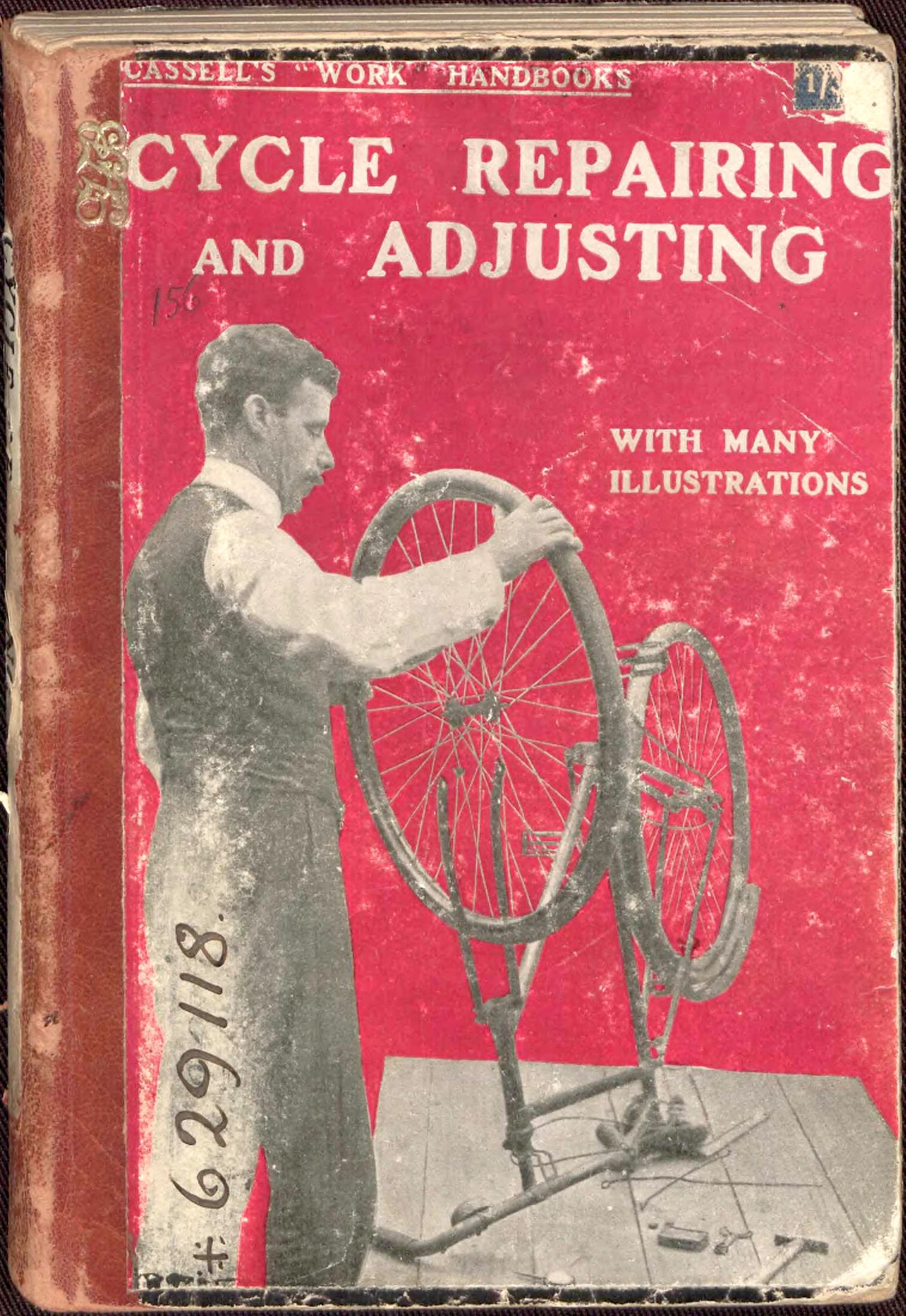 Page 1
 Page 2
 Page 3
 Page 4
 Page 5
 Page 6
 Page 7
 Page 8
 Page 9
 Page 10
 Page 11
 Page 12
 Page 13
 Page 14
 Page 15
 Page 16
 Page 17
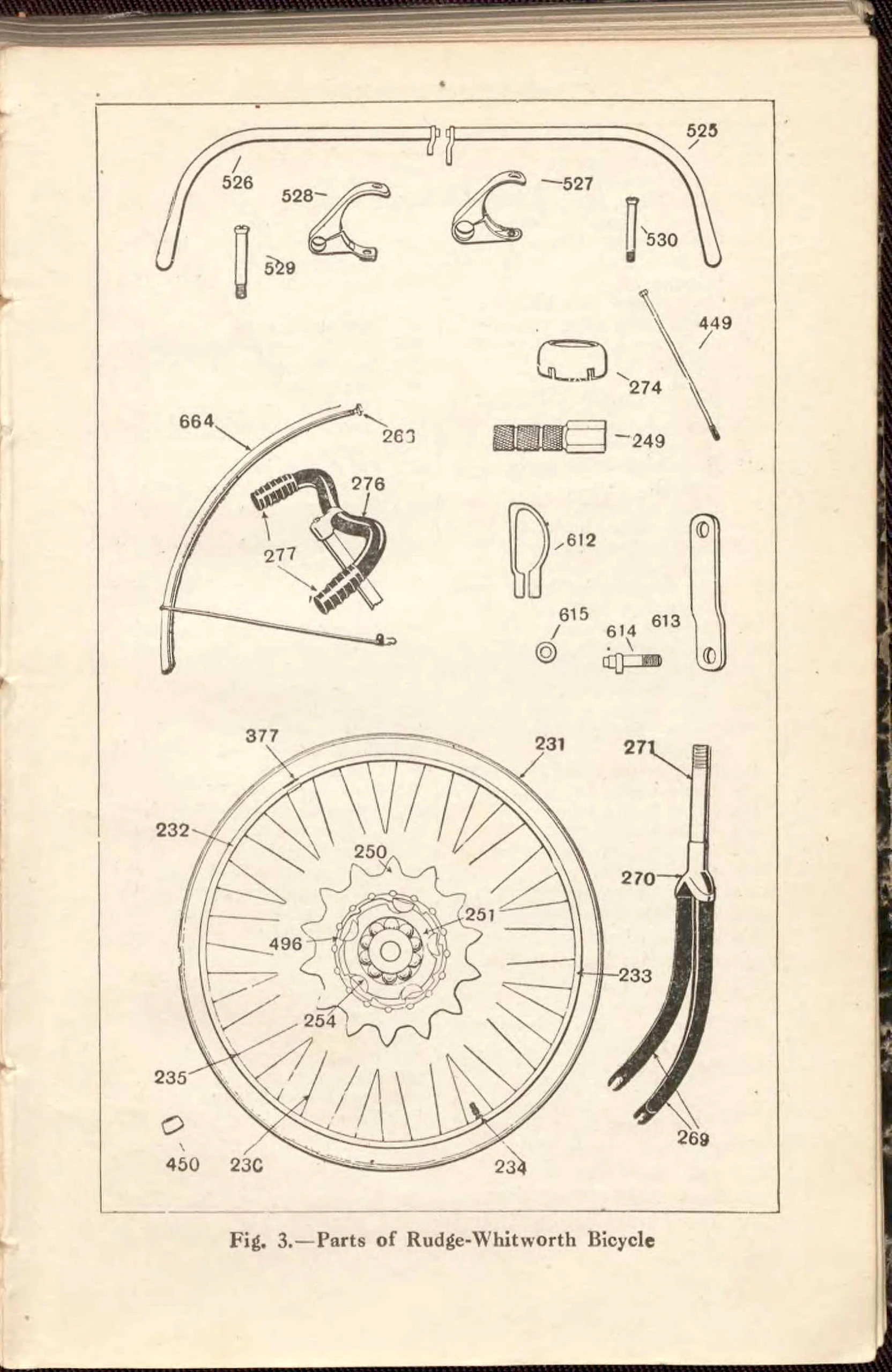
 Page 18
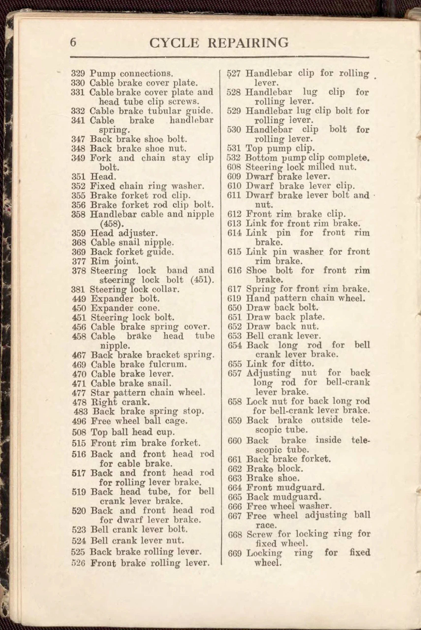
 Page 19
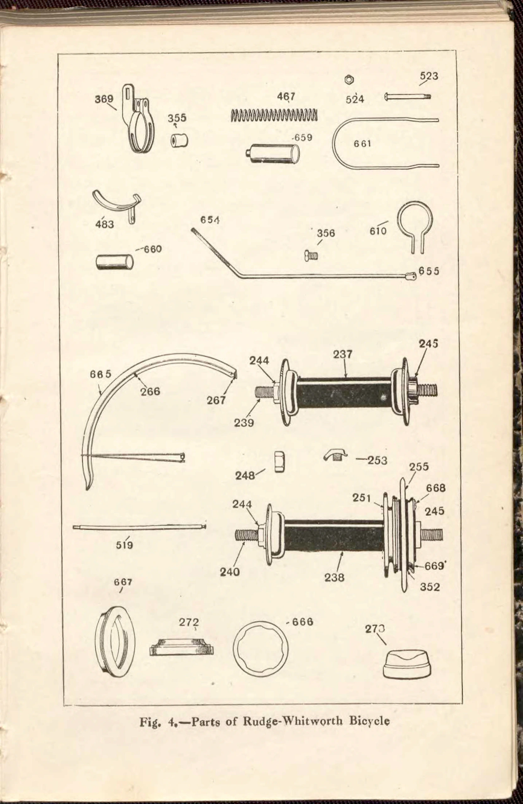
 Page 20
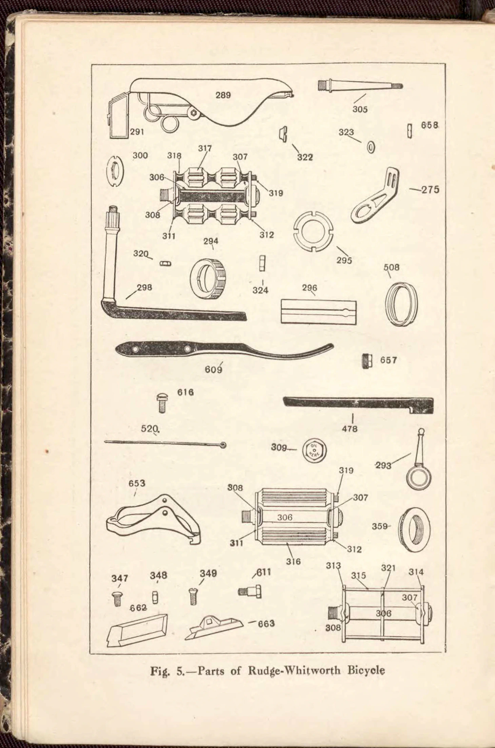
 Page 21
 Page 22
 Page 23
 Page 24
 Page 25
 Page 26
 Page 27
 Page 28
 Page 29
 Page 30
 Page 31
 Page 32
 Page 33
 Page 34
 Page 35
 Page 36
 Page 37
 Page 38
 Page 39
 Page 40
 Page 41
 Page 42
 Page 43
 Page 44
 Page 45
 Page 46
 Page 47
 Page 48
 Page 49
 Page 50
 Page 51
 Page 52
 Page 53
 Page 54
 Page 55
 Page 56
 Page 57
 Page 58
 Page 59
 Page 60
 Page 61
 Page 62
 Page 63
 Page 64
 Page 65
 Page 66
 Page 67
 Page 68
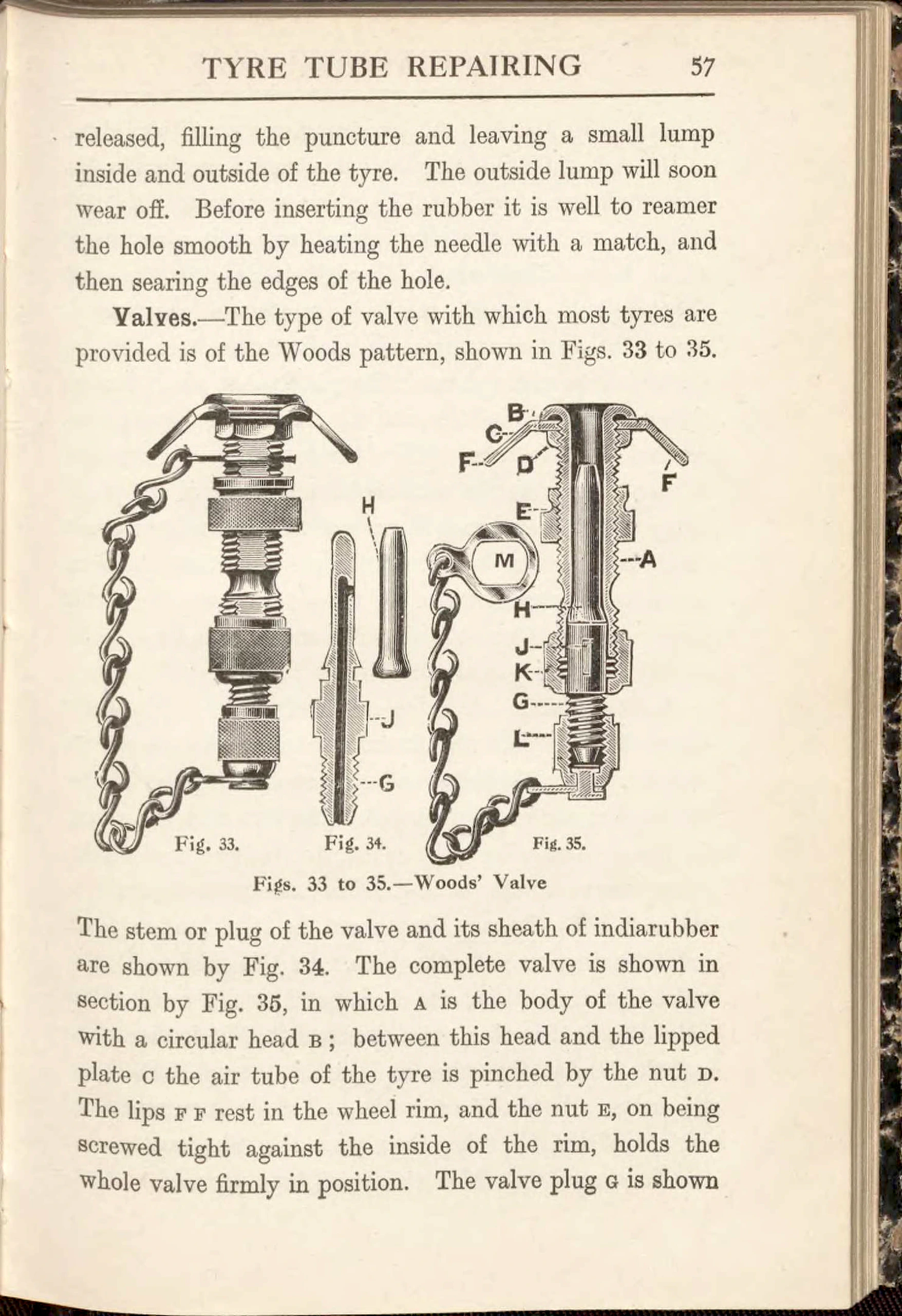 Page 69
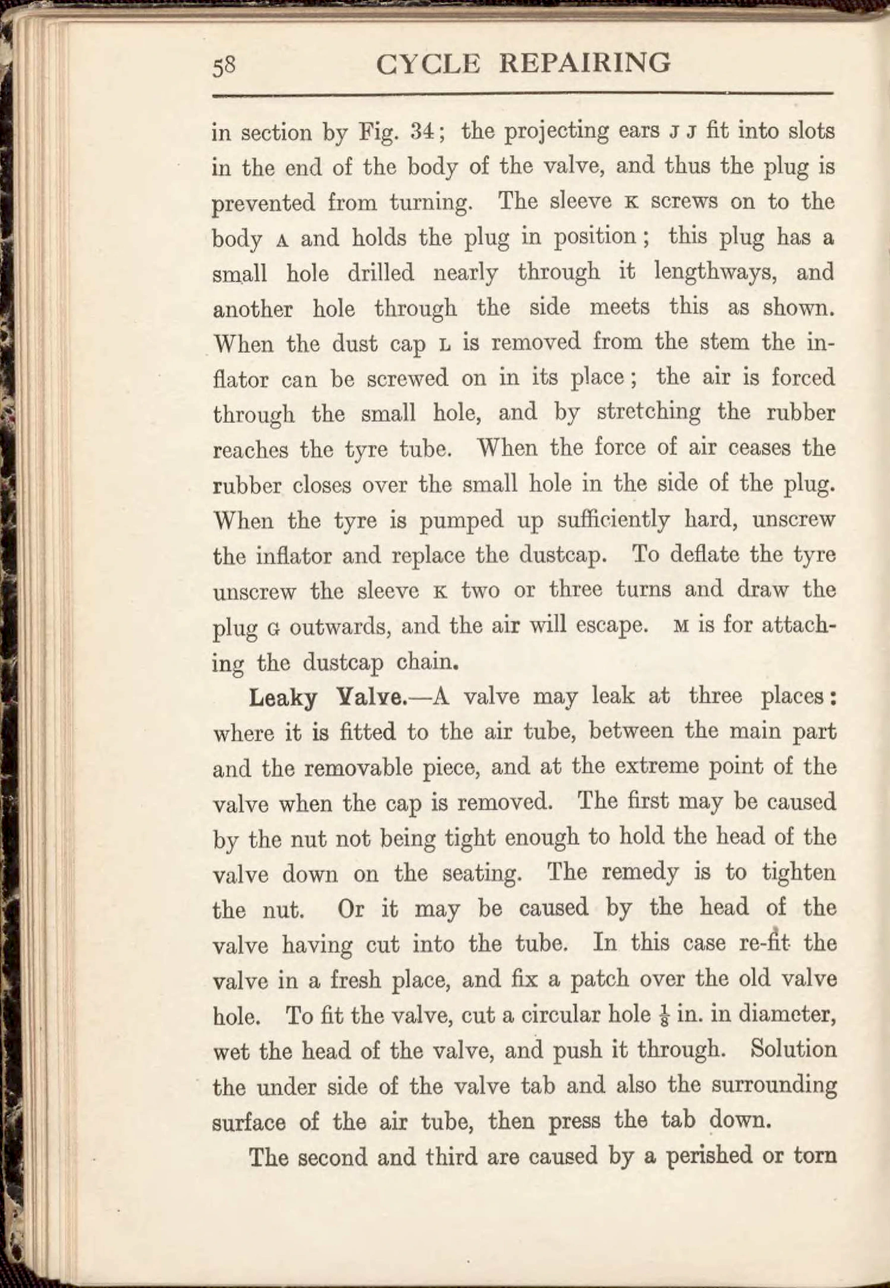 Page 70
 Page 71
 Page 72
 Page 73
 Page 74
 Page 75
 Page 76
 Page 77
 Page 78
 Page 79
 Page 80
 Page 81
 Page 82
 Page 83
 Page 84
 Page 85
 Page 86
 Page 87
 Page 88
 Page 89
 Page 90
 Page 91
 Page 92
 Page 93
 Page 94
 Page 95
 Page 96
 Page 97
 Page 98
 Page 99
 Page 100
 Page 101
 Page 102
 Page 103
 Page 104
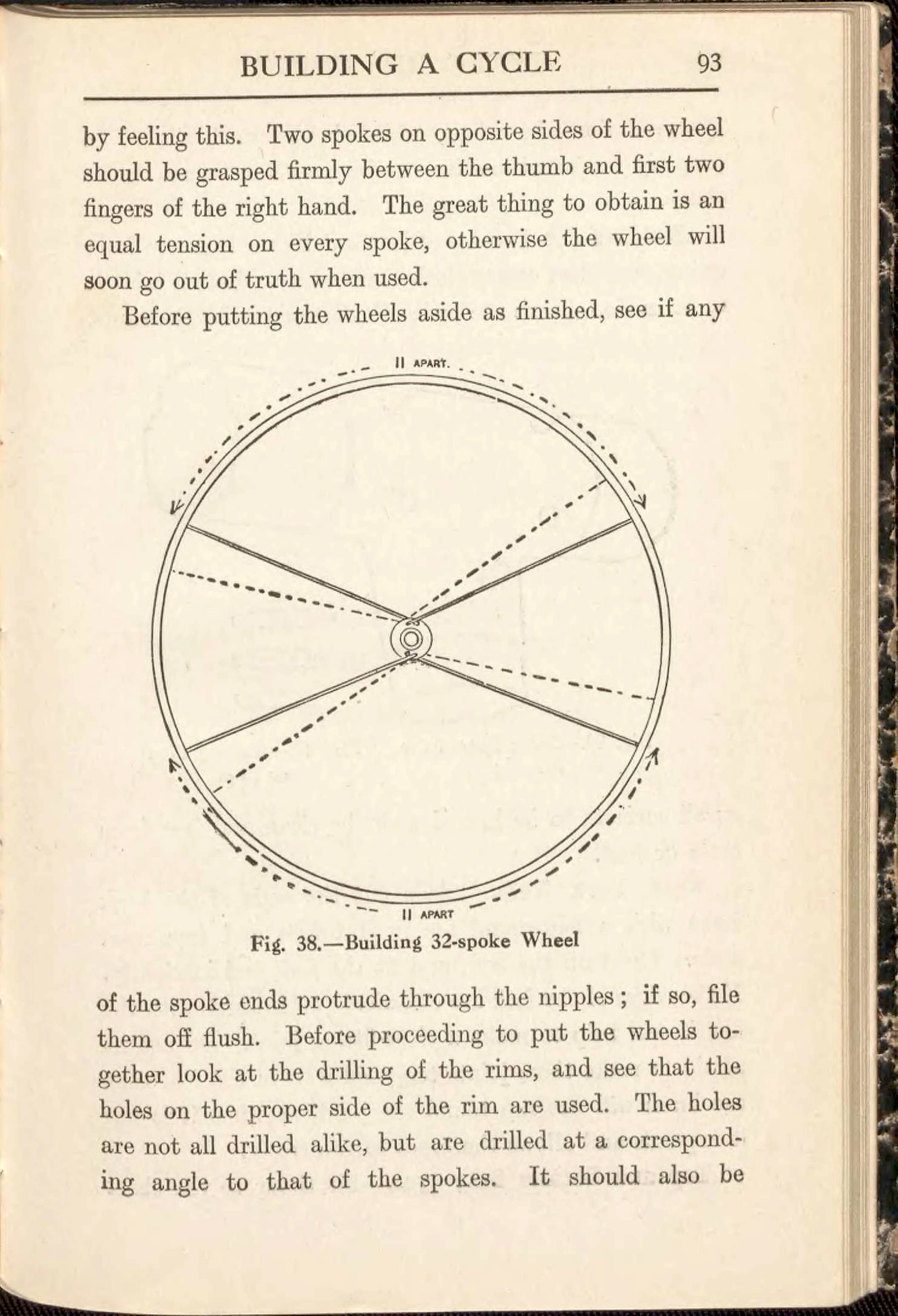 Page 105
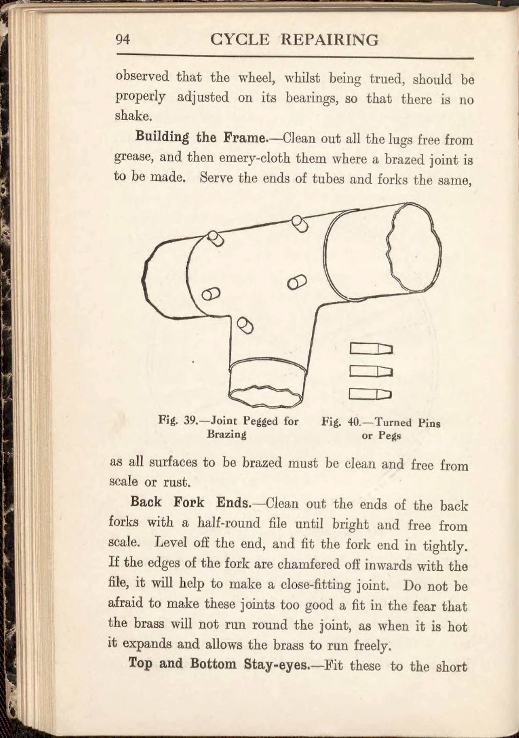 Page 106
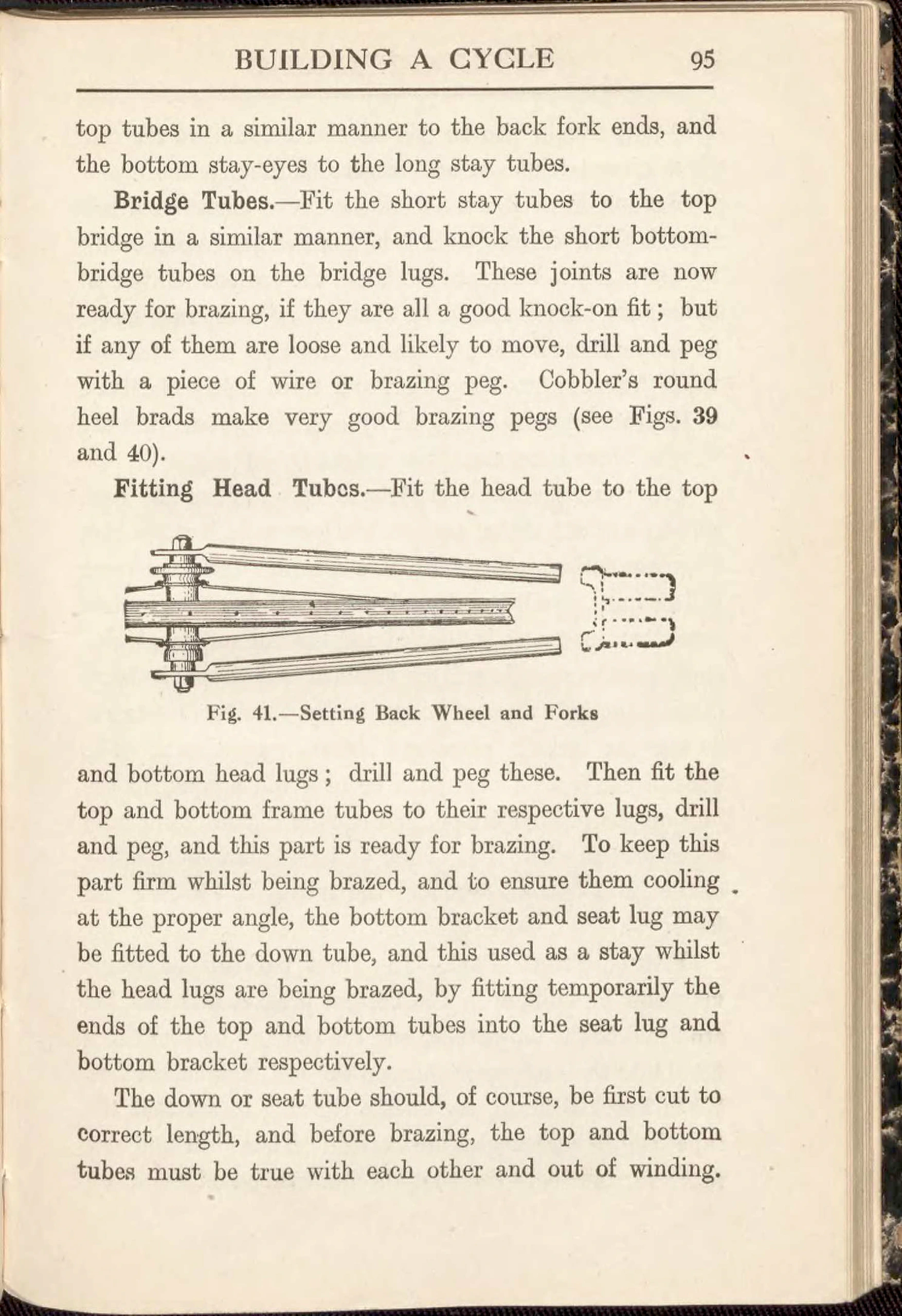 Page 107
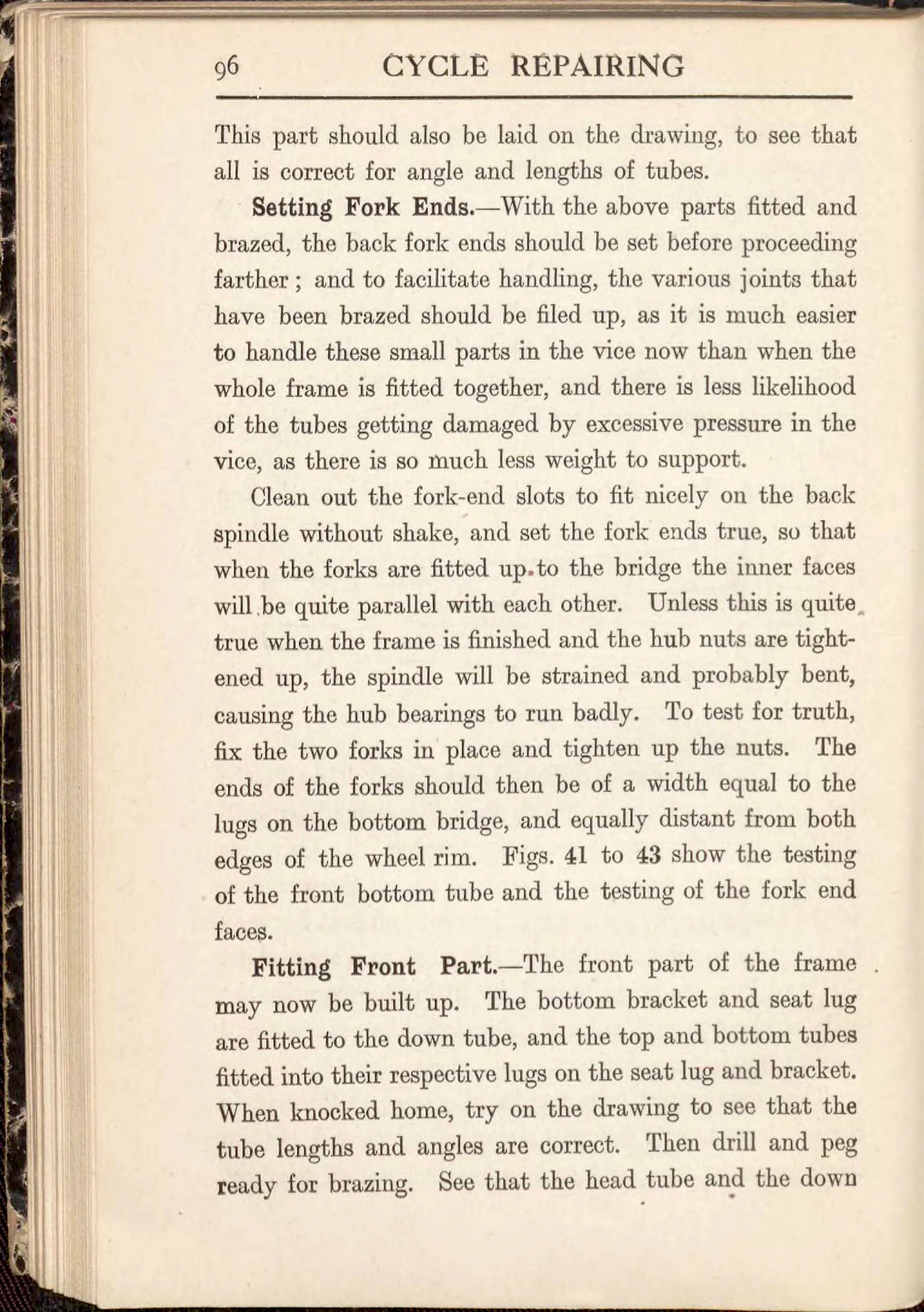 Page 108
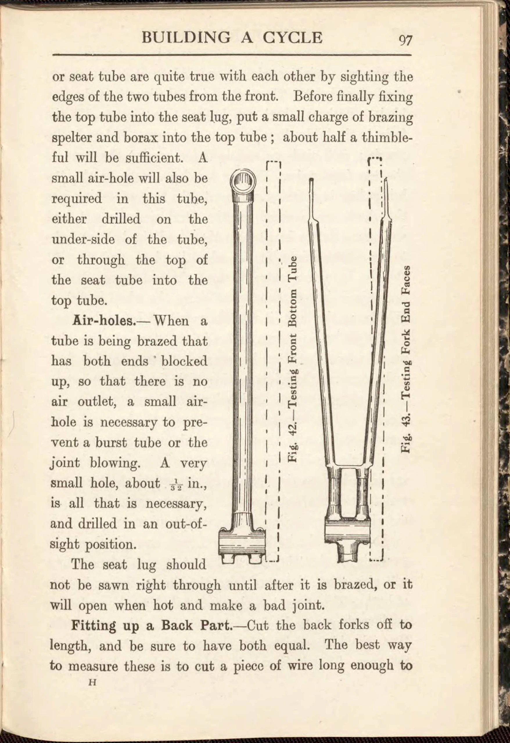 Page 109
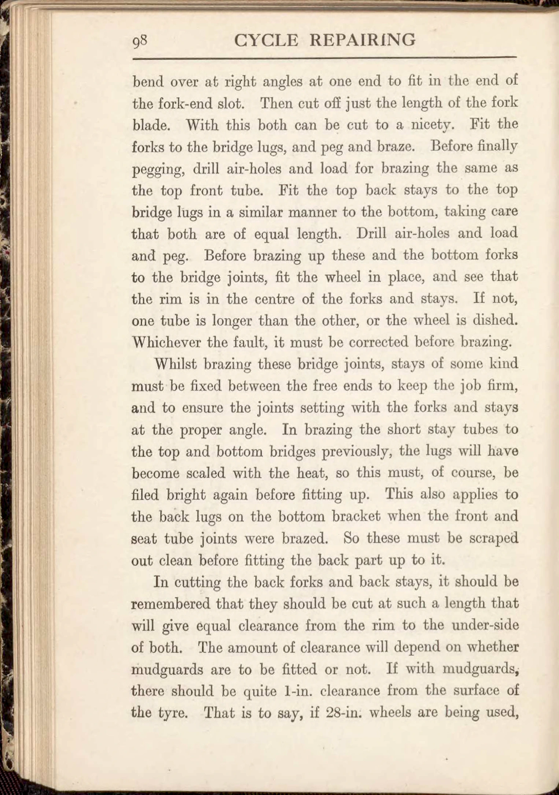 Page 110
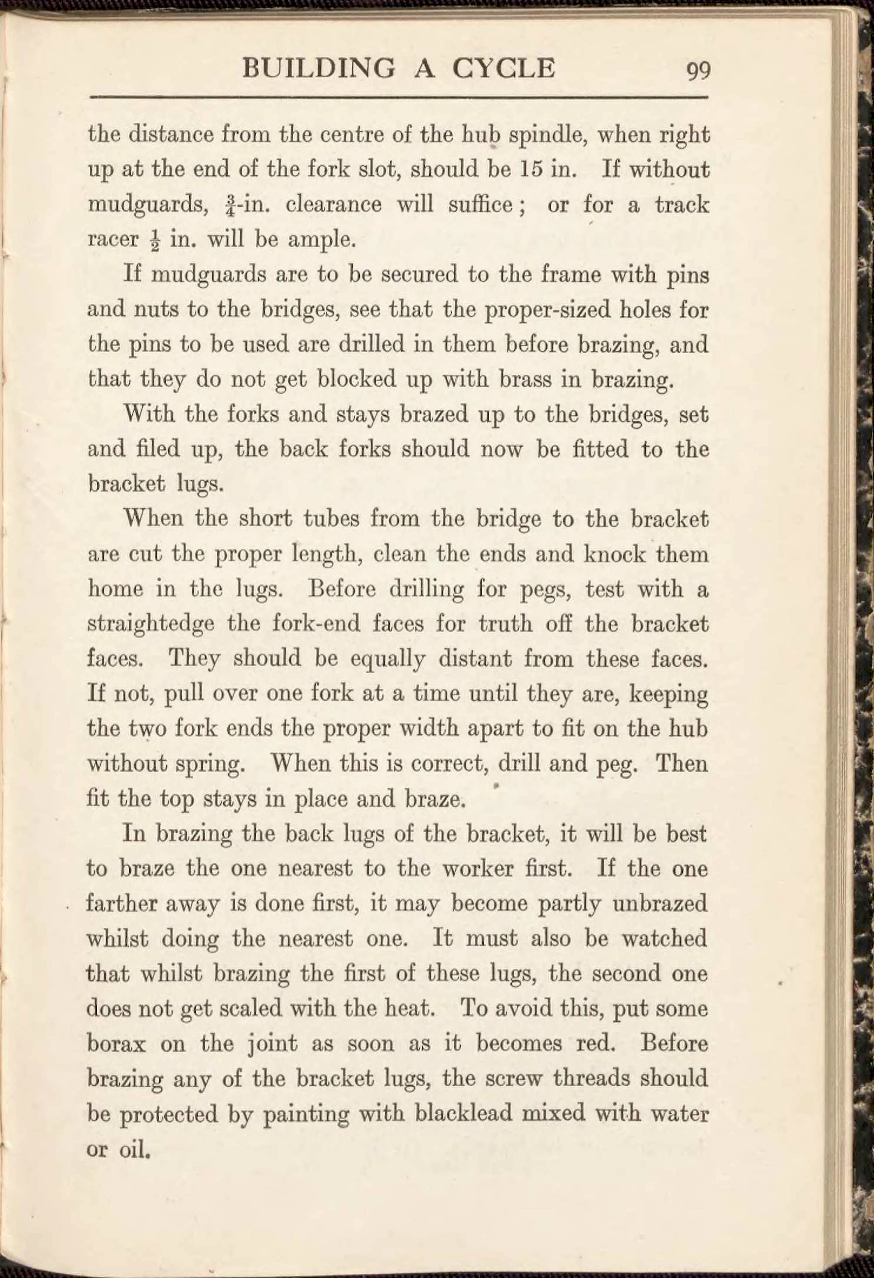 Page 111
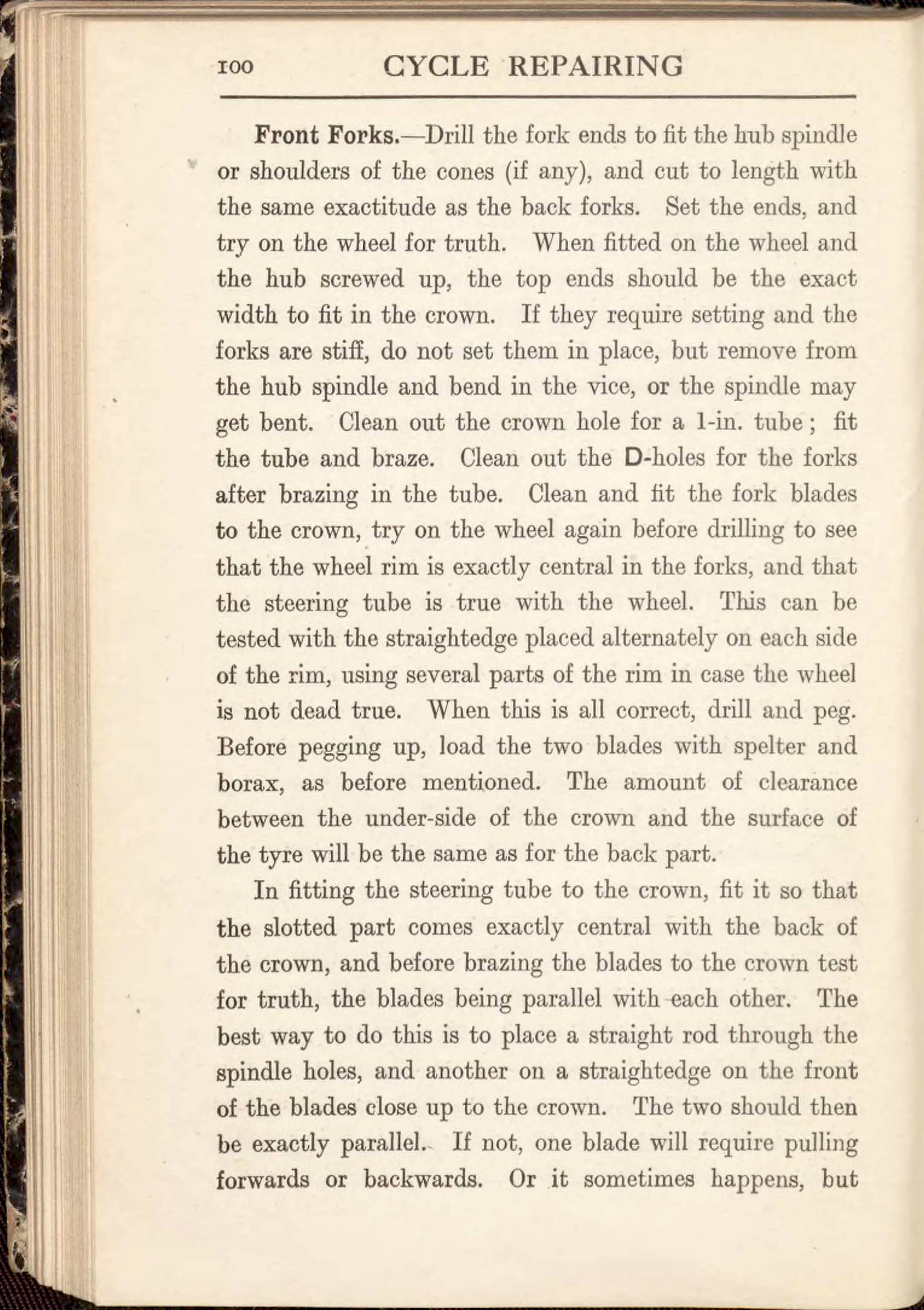 Page 112
 Page 113
 Page 114
 Page 115
 Page 116
 Page 117
 Page 118
 Page 119
 Page 120
 Page 121
 Page 122
 Page 123
 Page 124
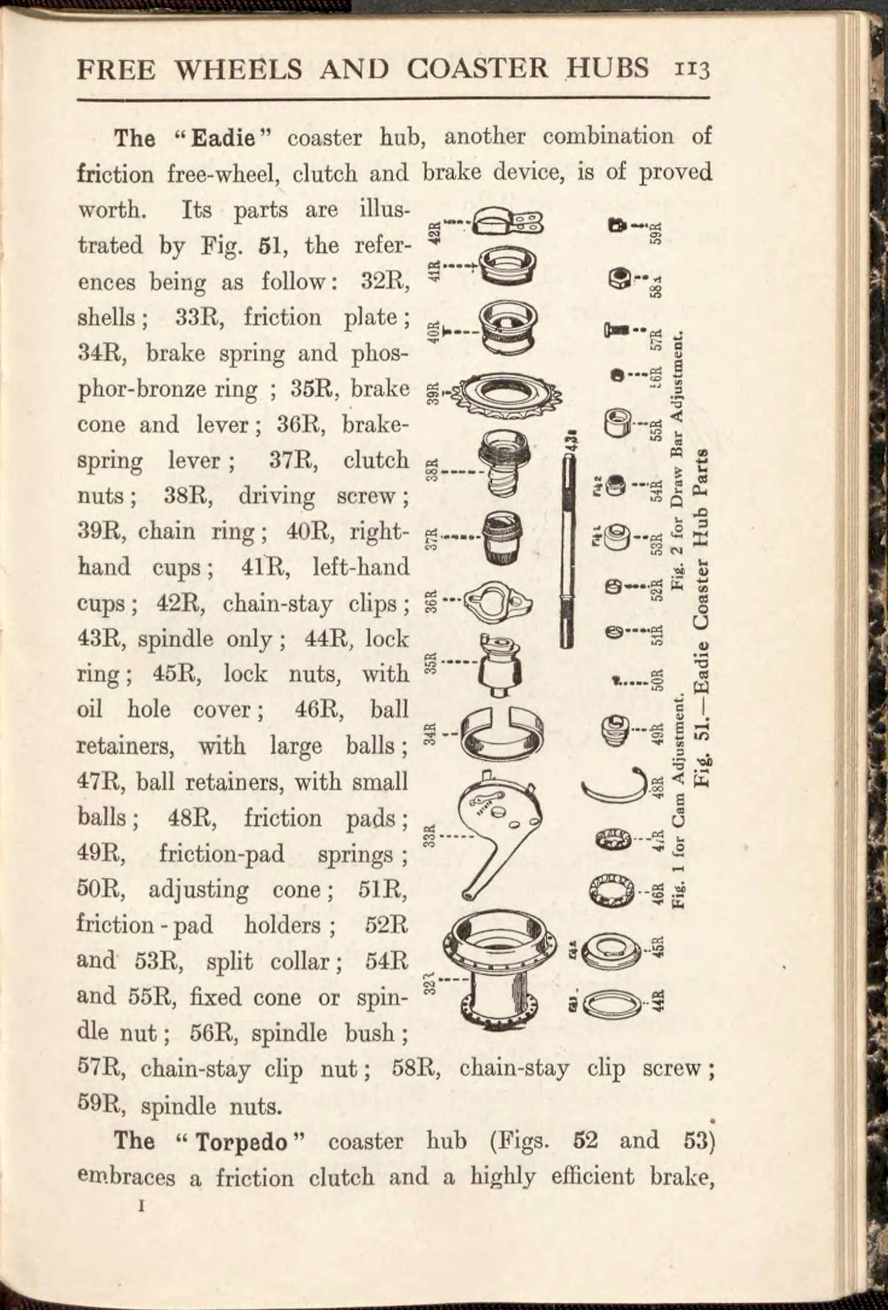 Page 125
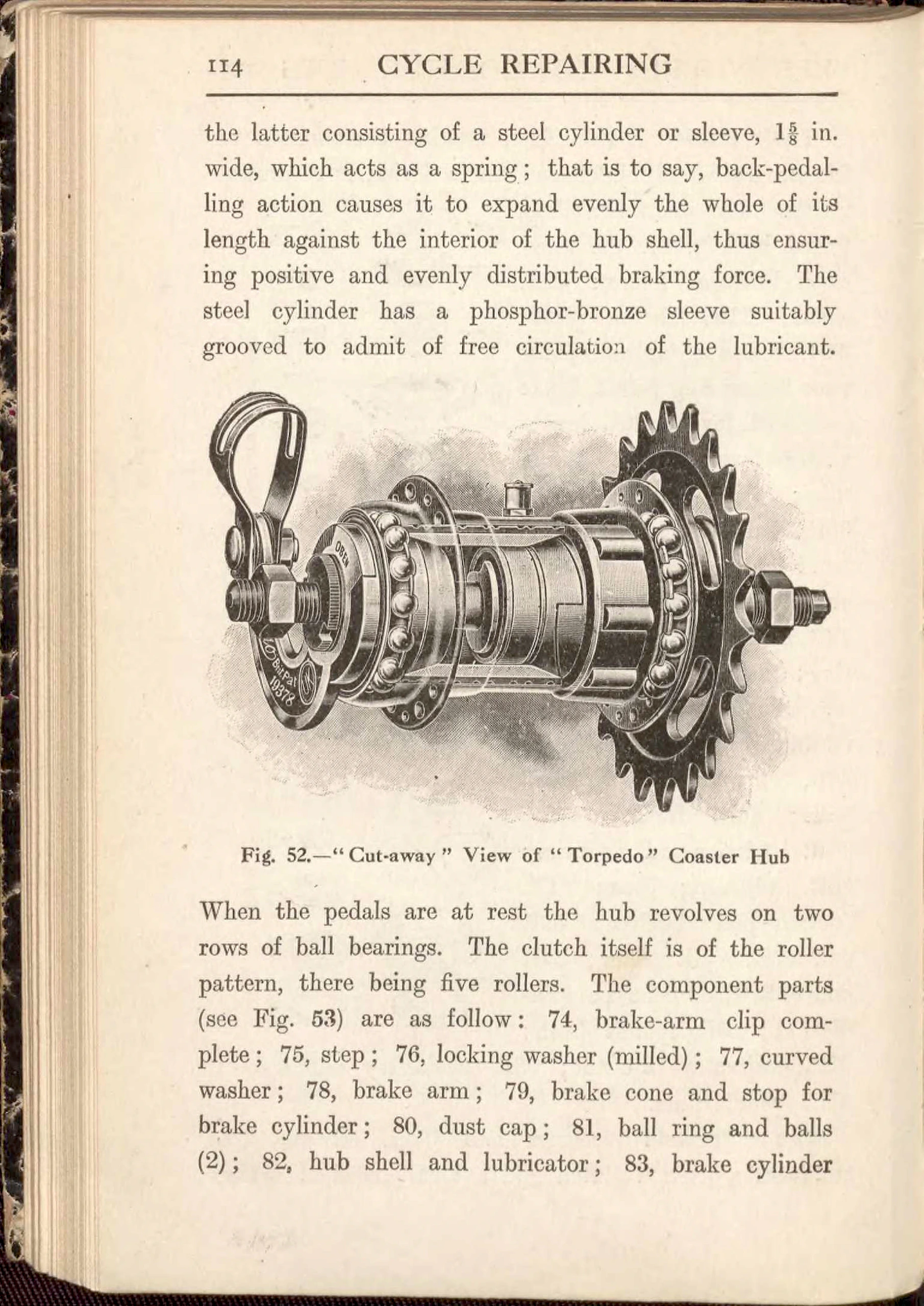 Page 126
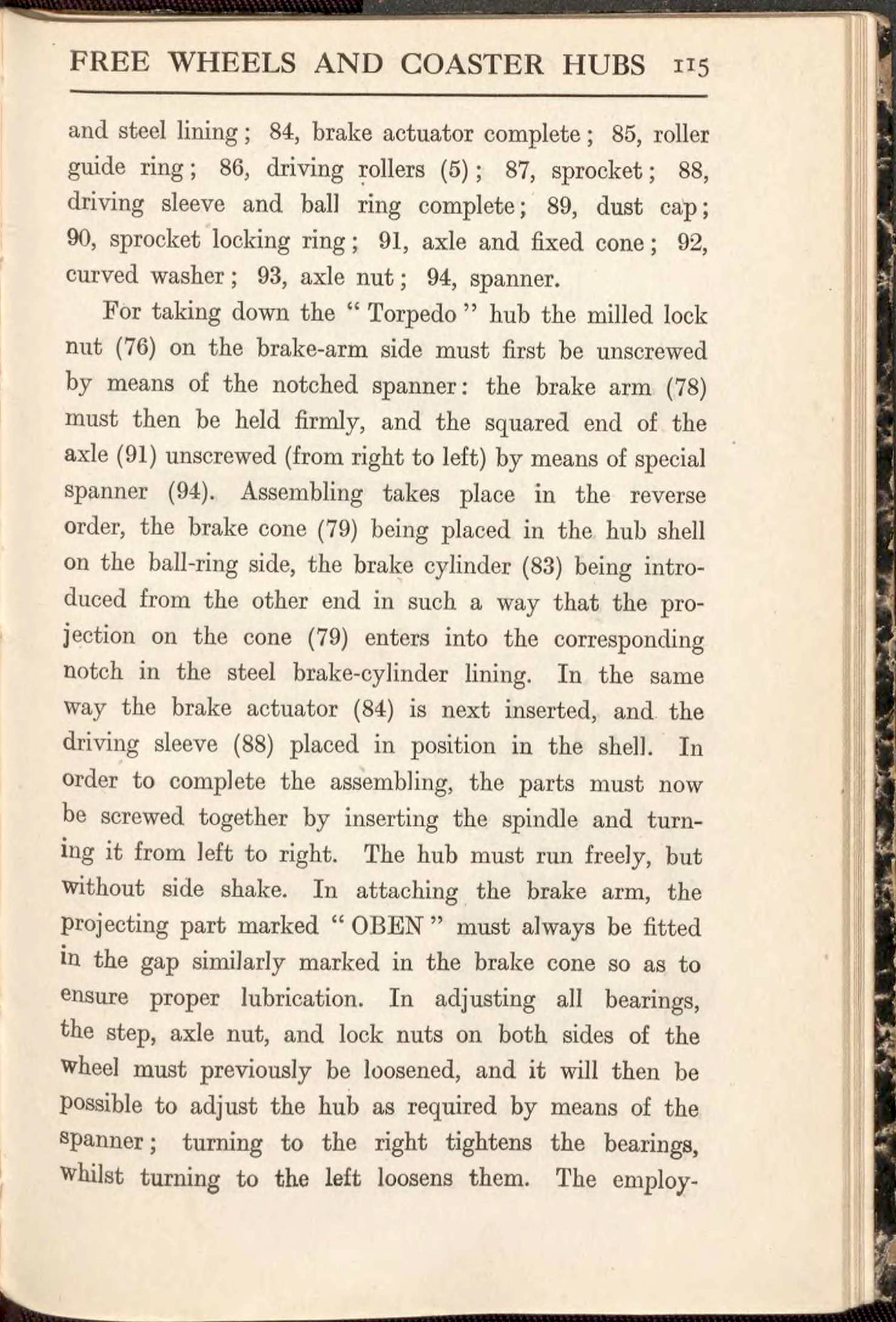 Page 127
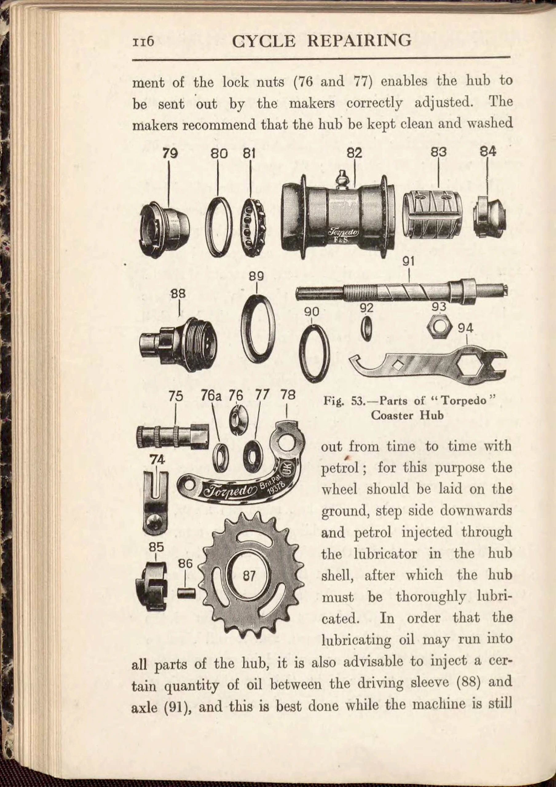 Page 128
 Page 129
 Page 130
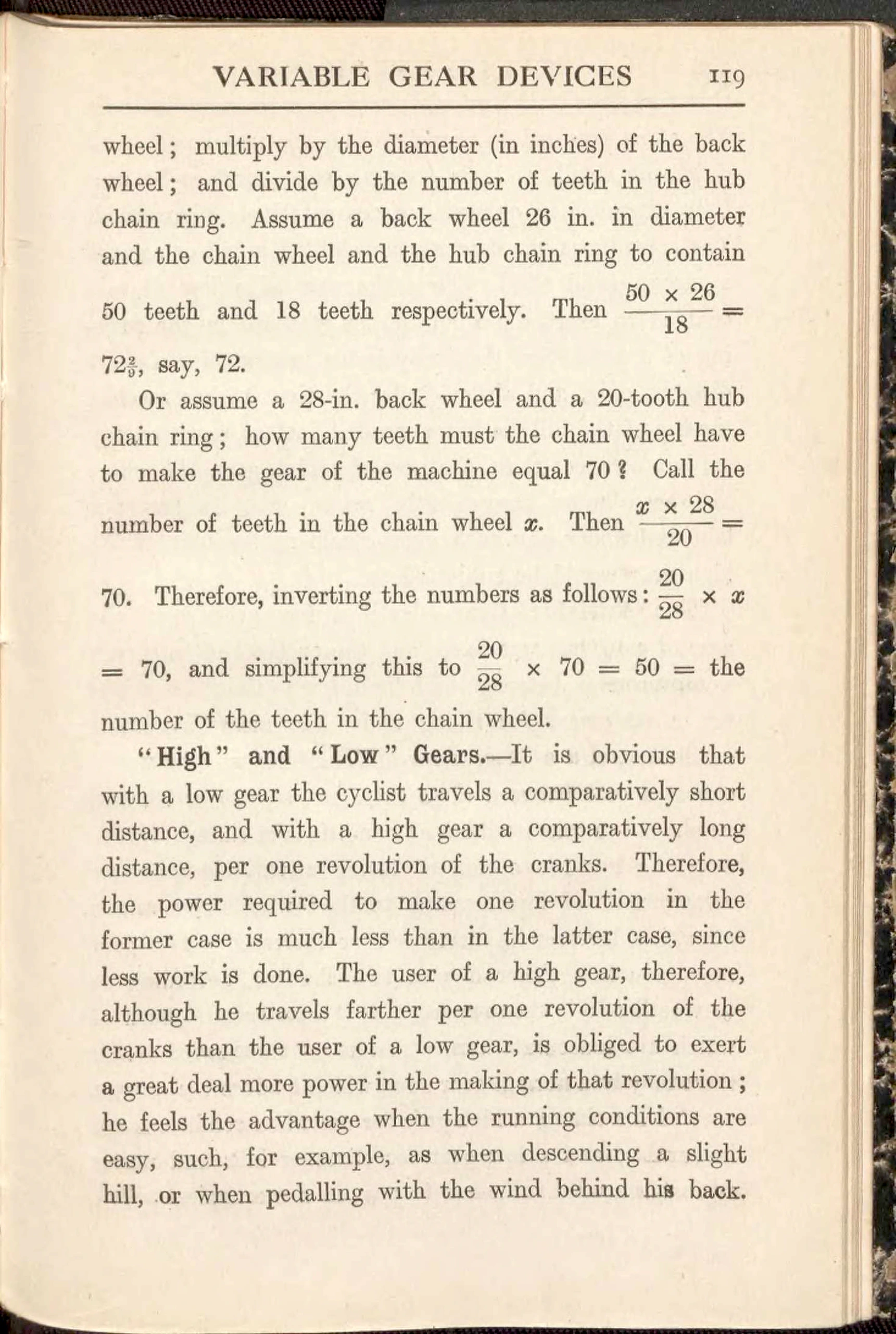 Page 131
 Page 132
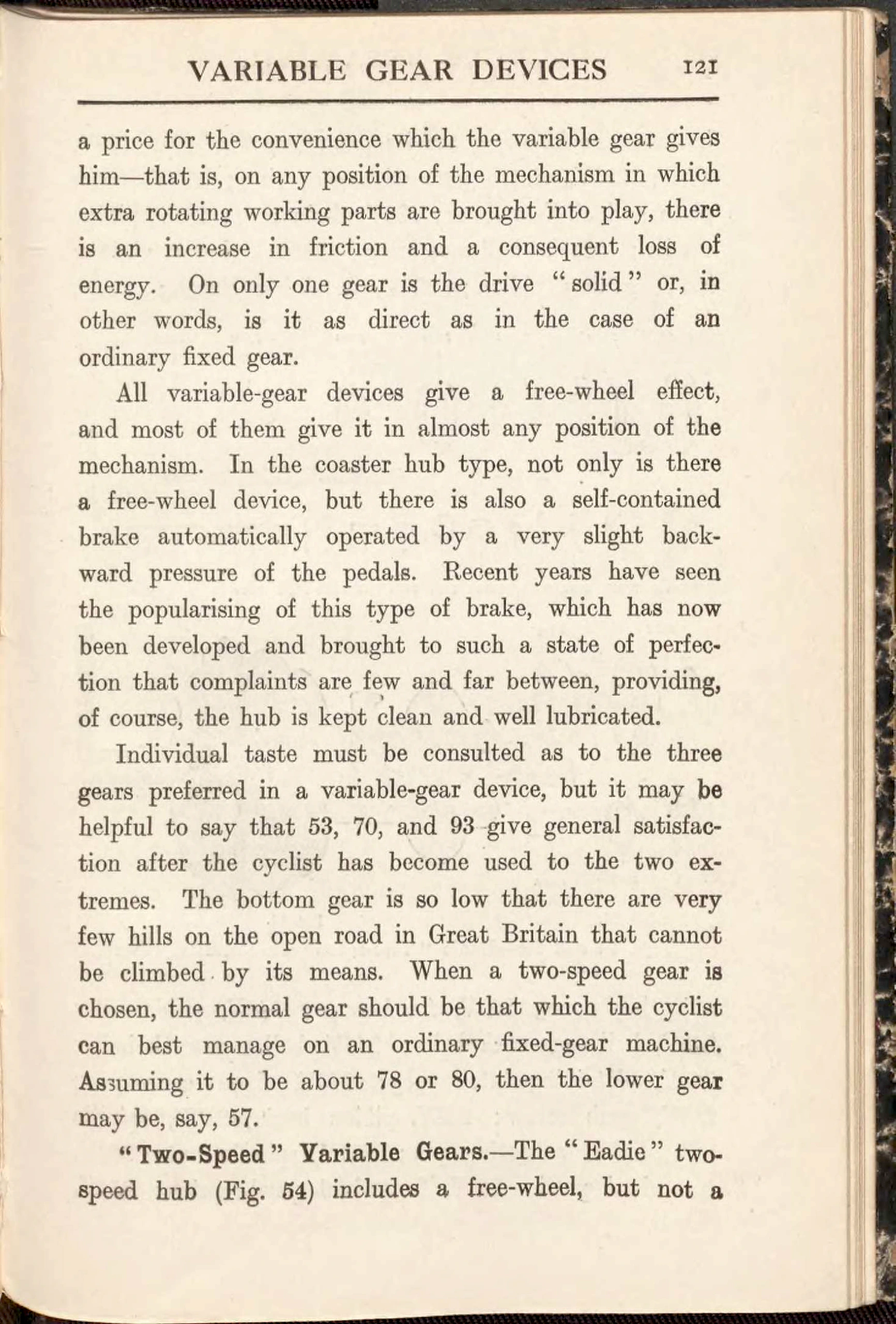 Page 133
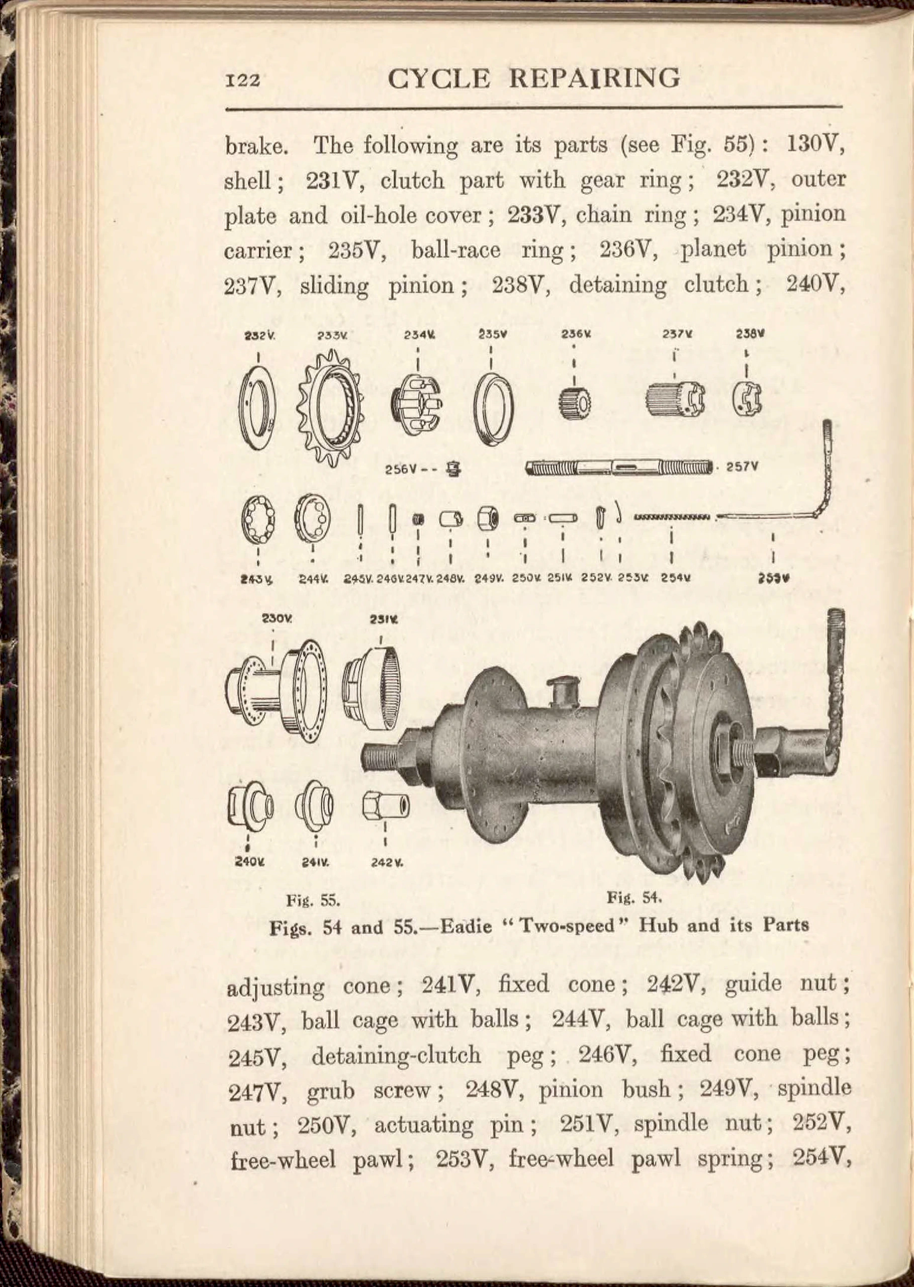 Page 134
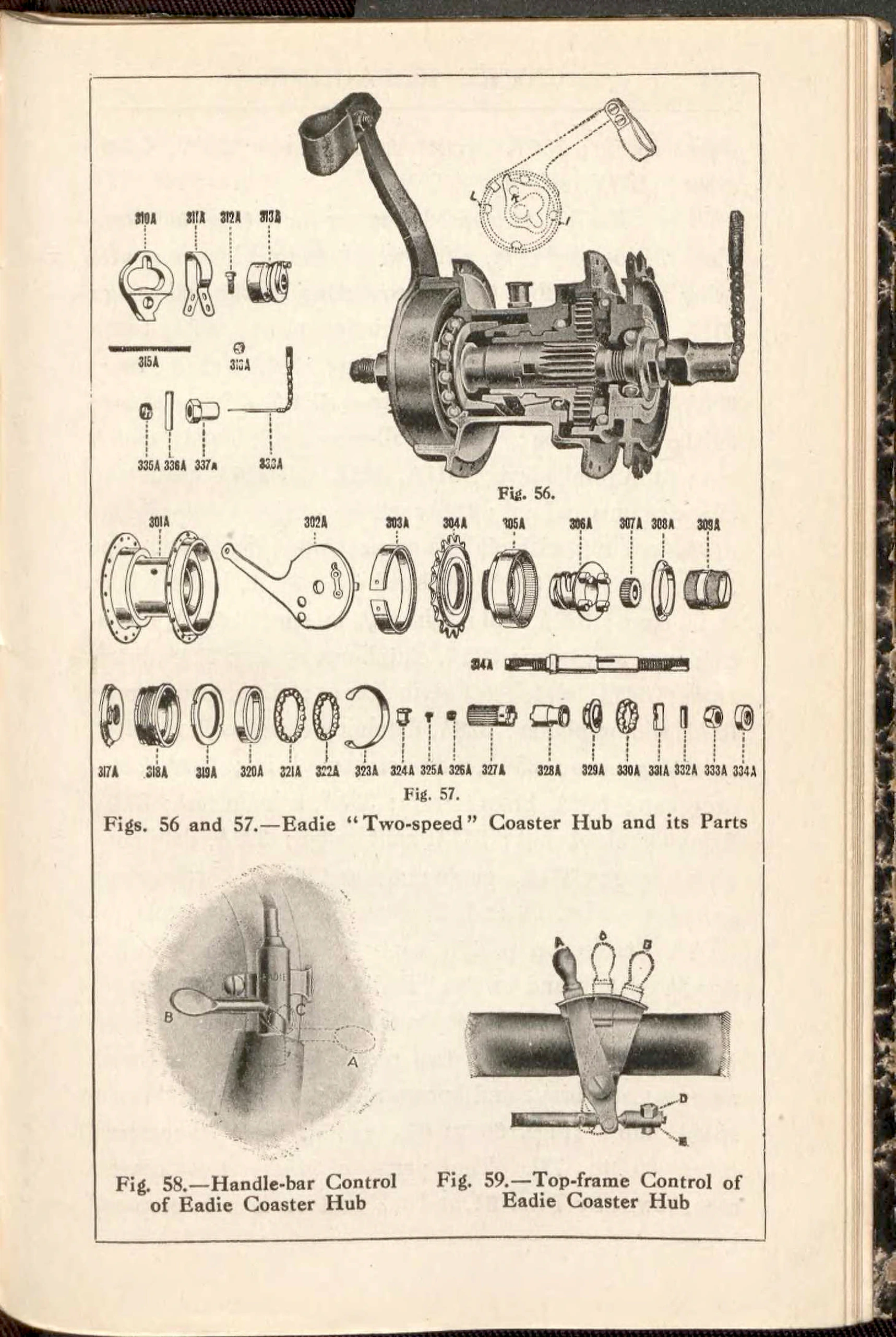 Page 135
 Page 136
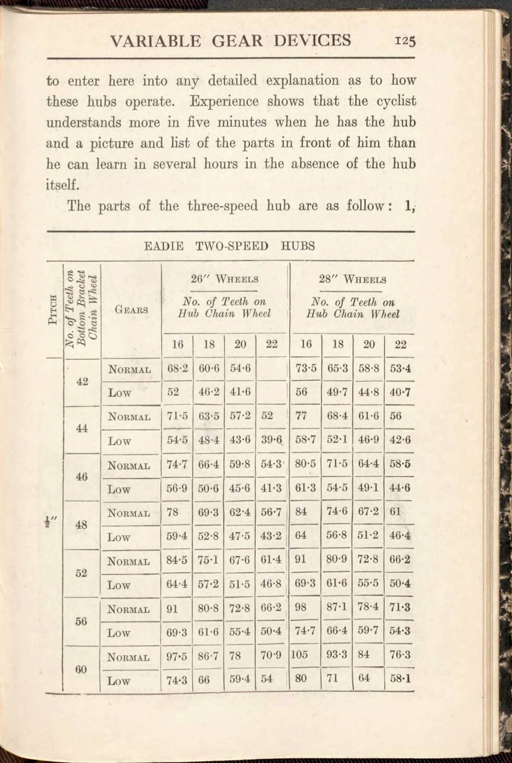 Page 137
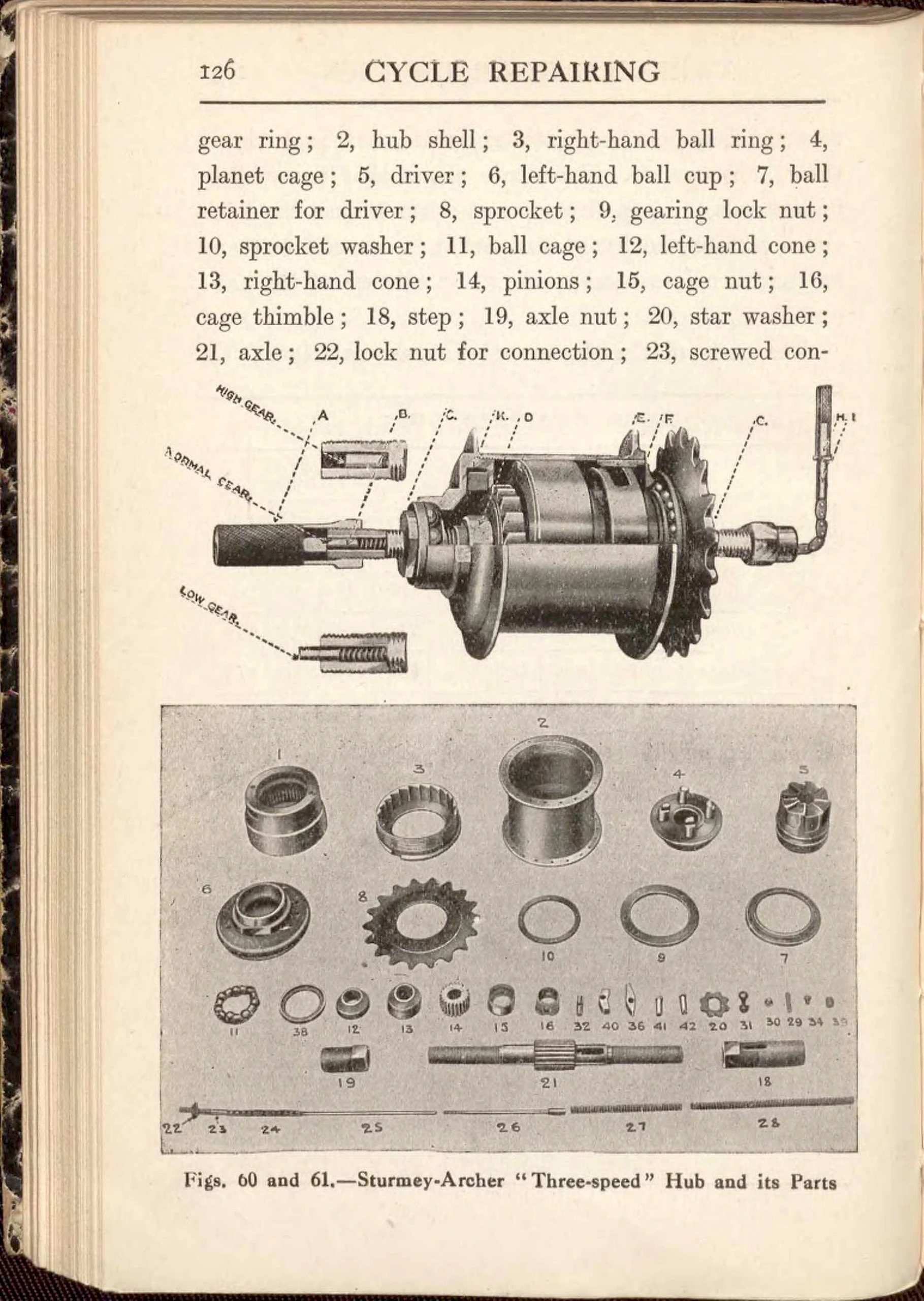 Page 138
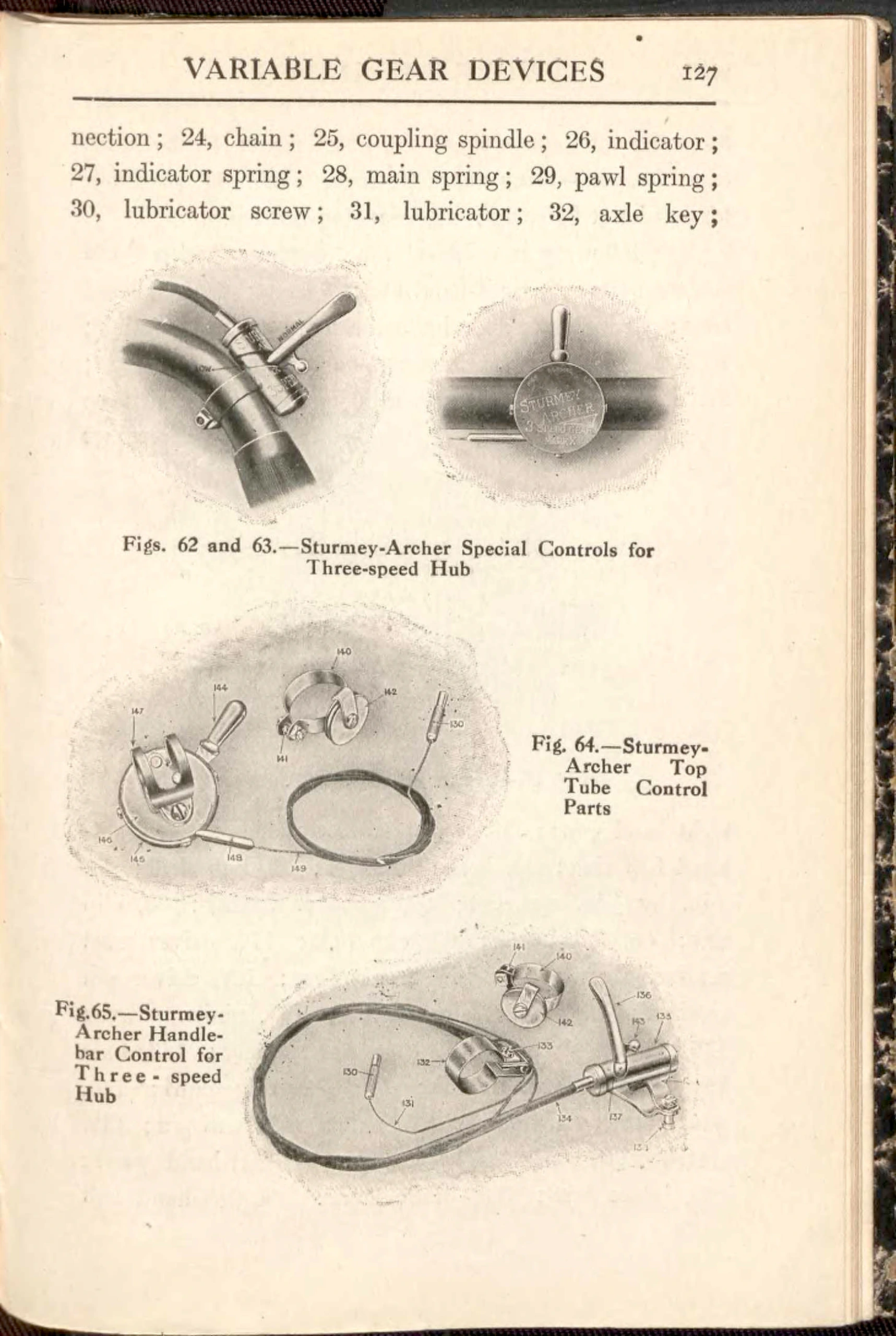 Page 139
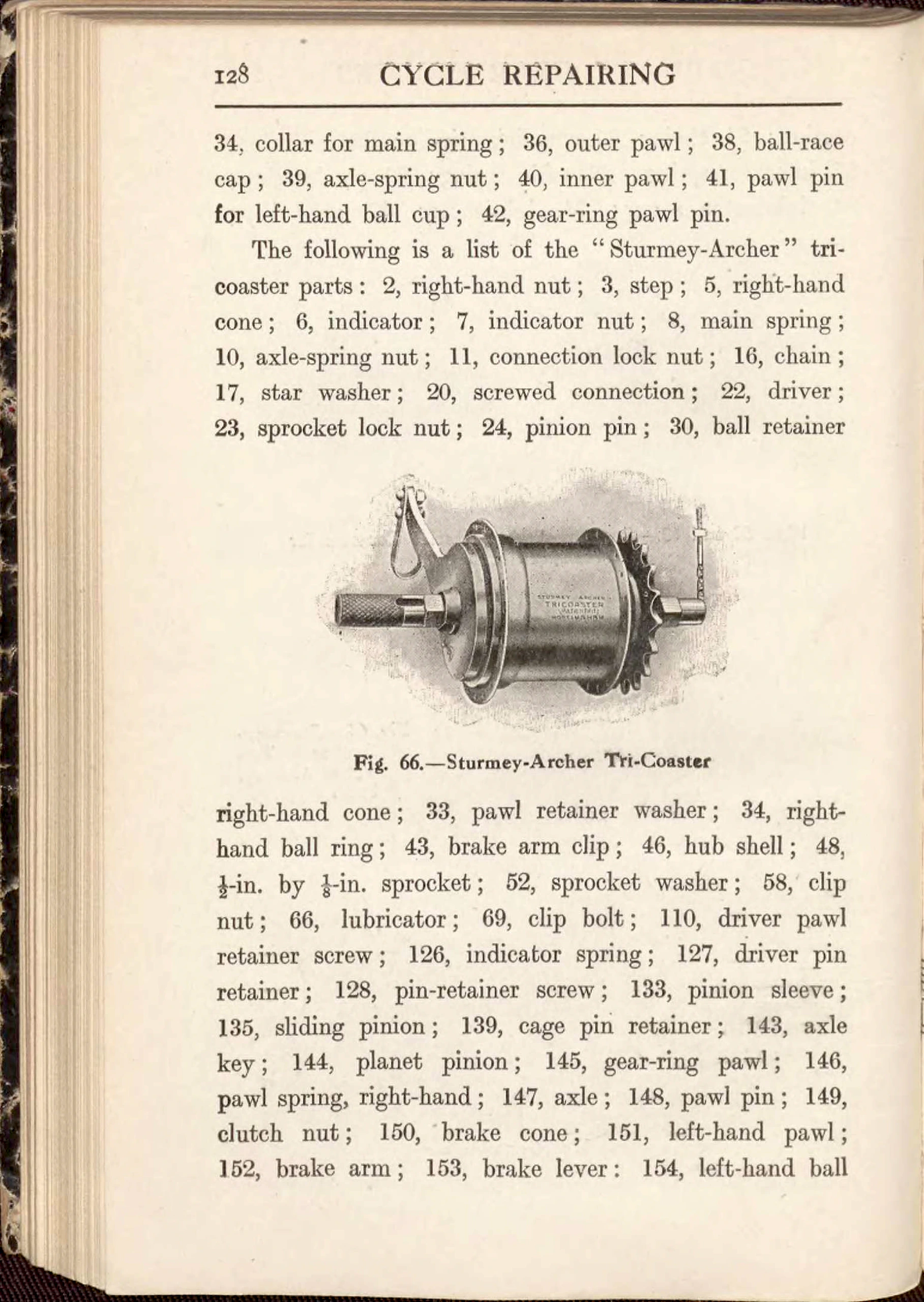 Page 140
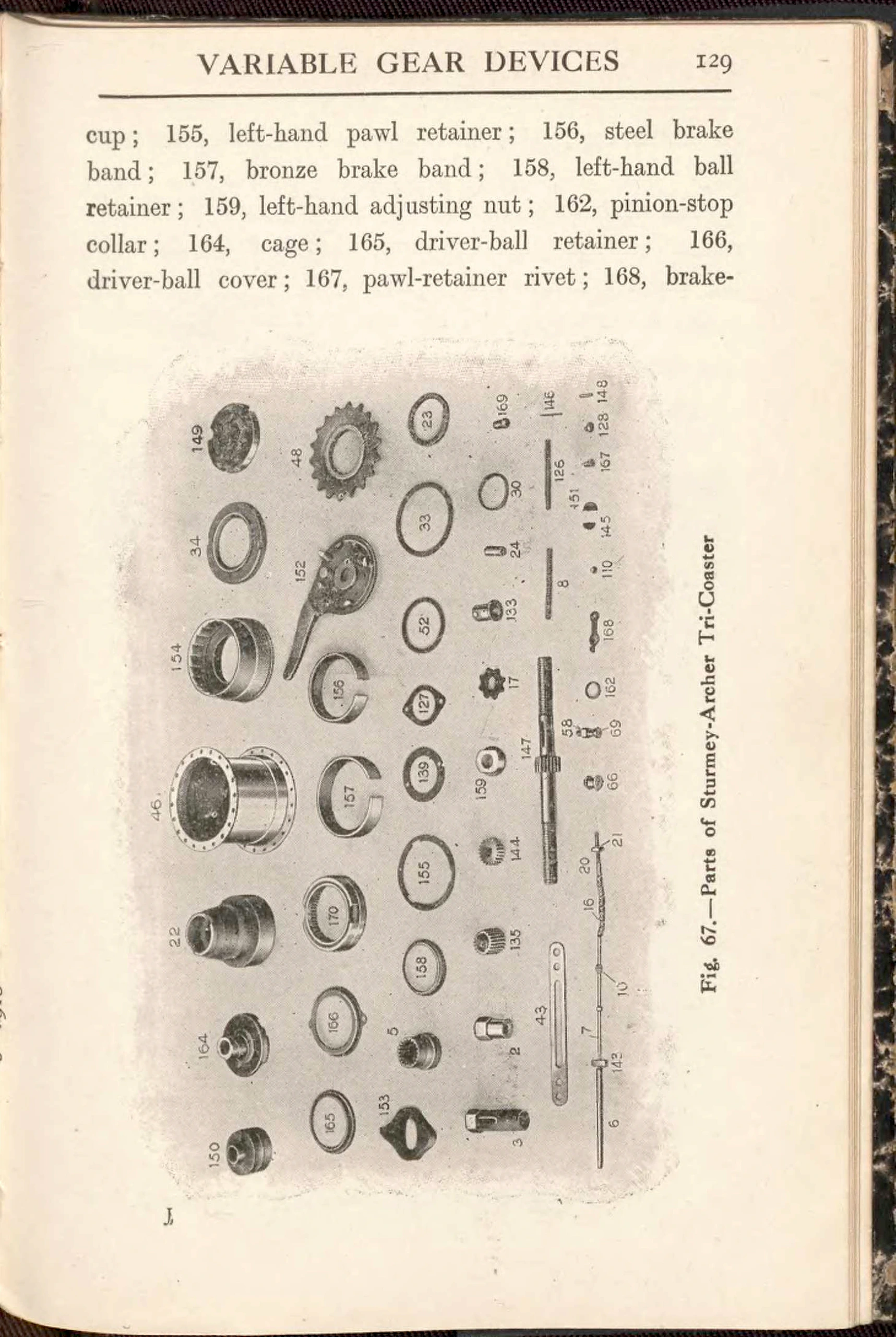 Page 141
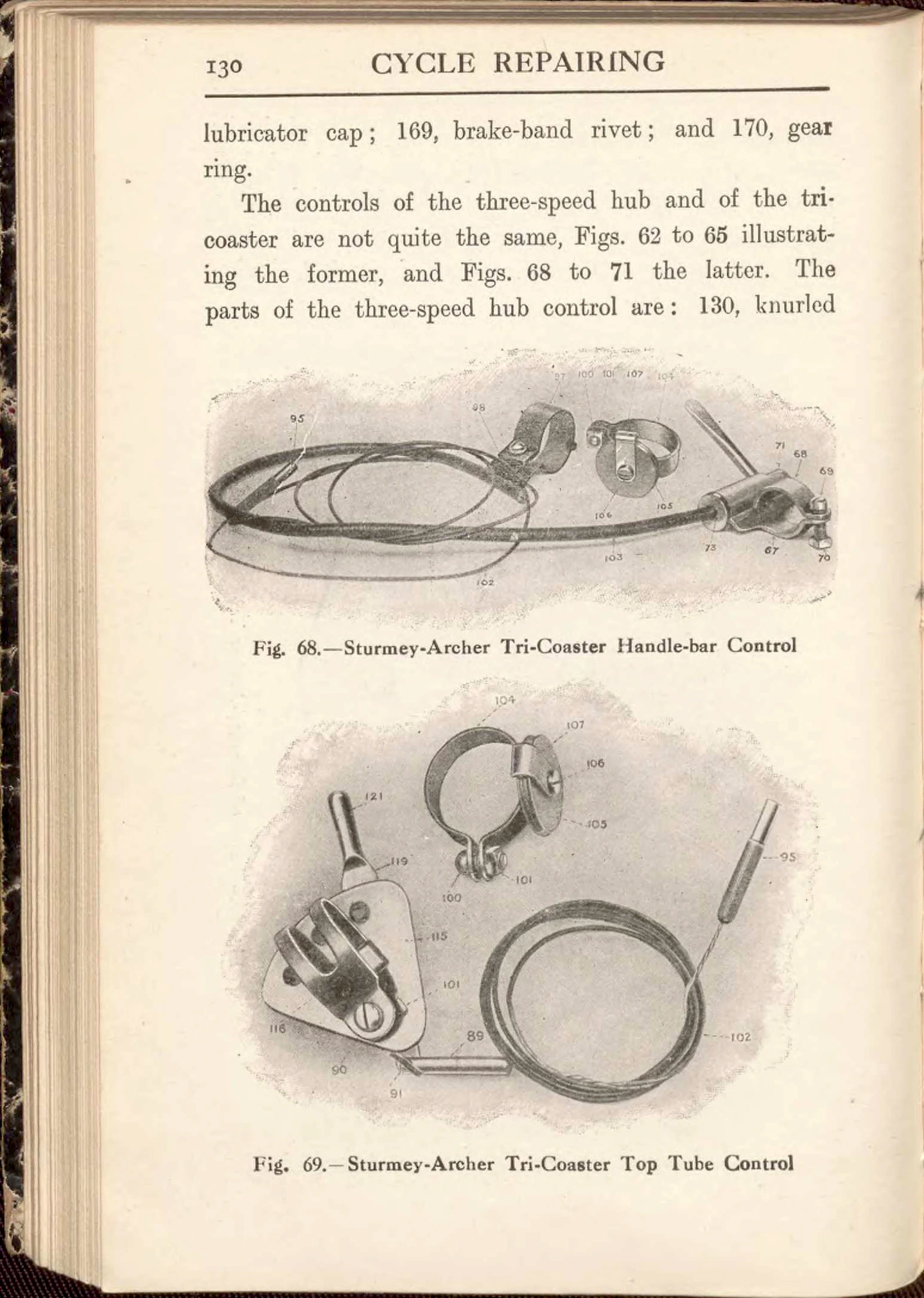 Page 142
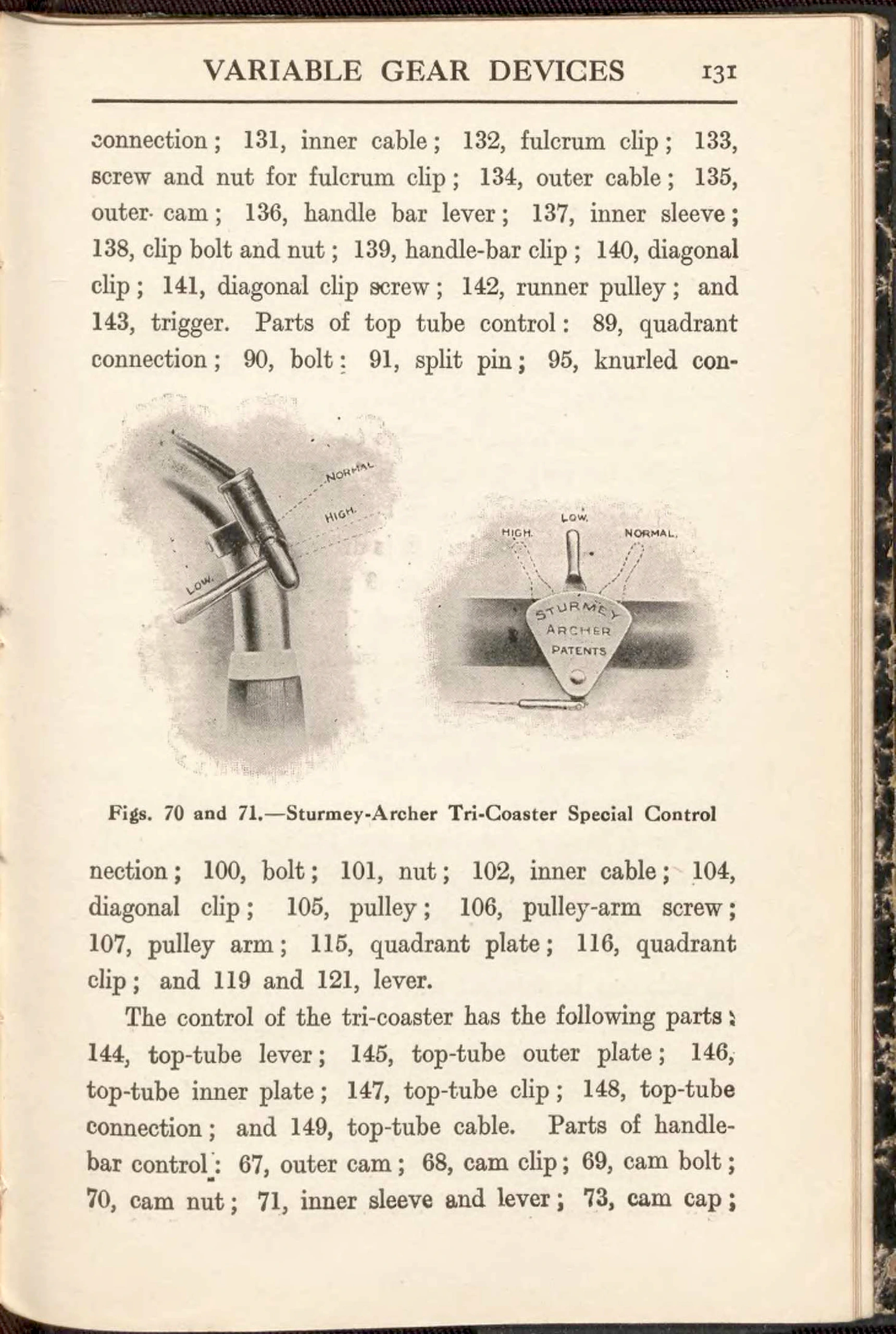 Page 143
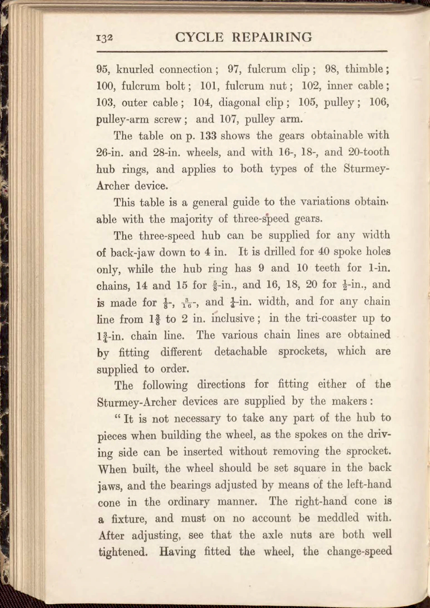 Page 144
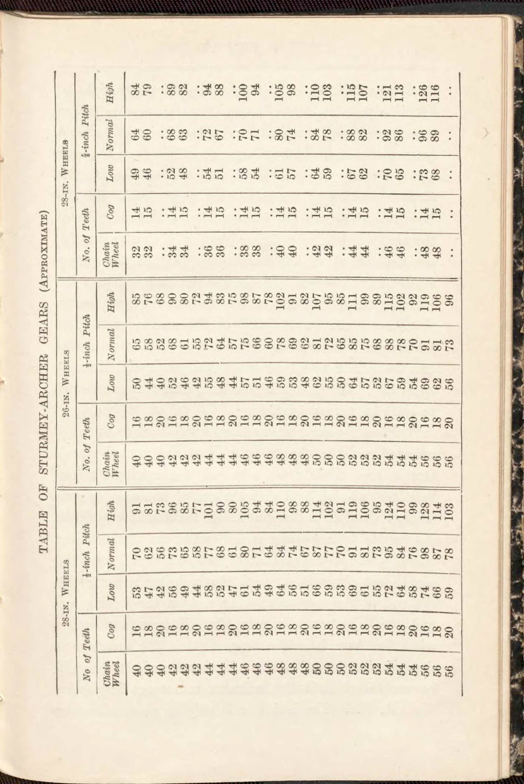 Page 145
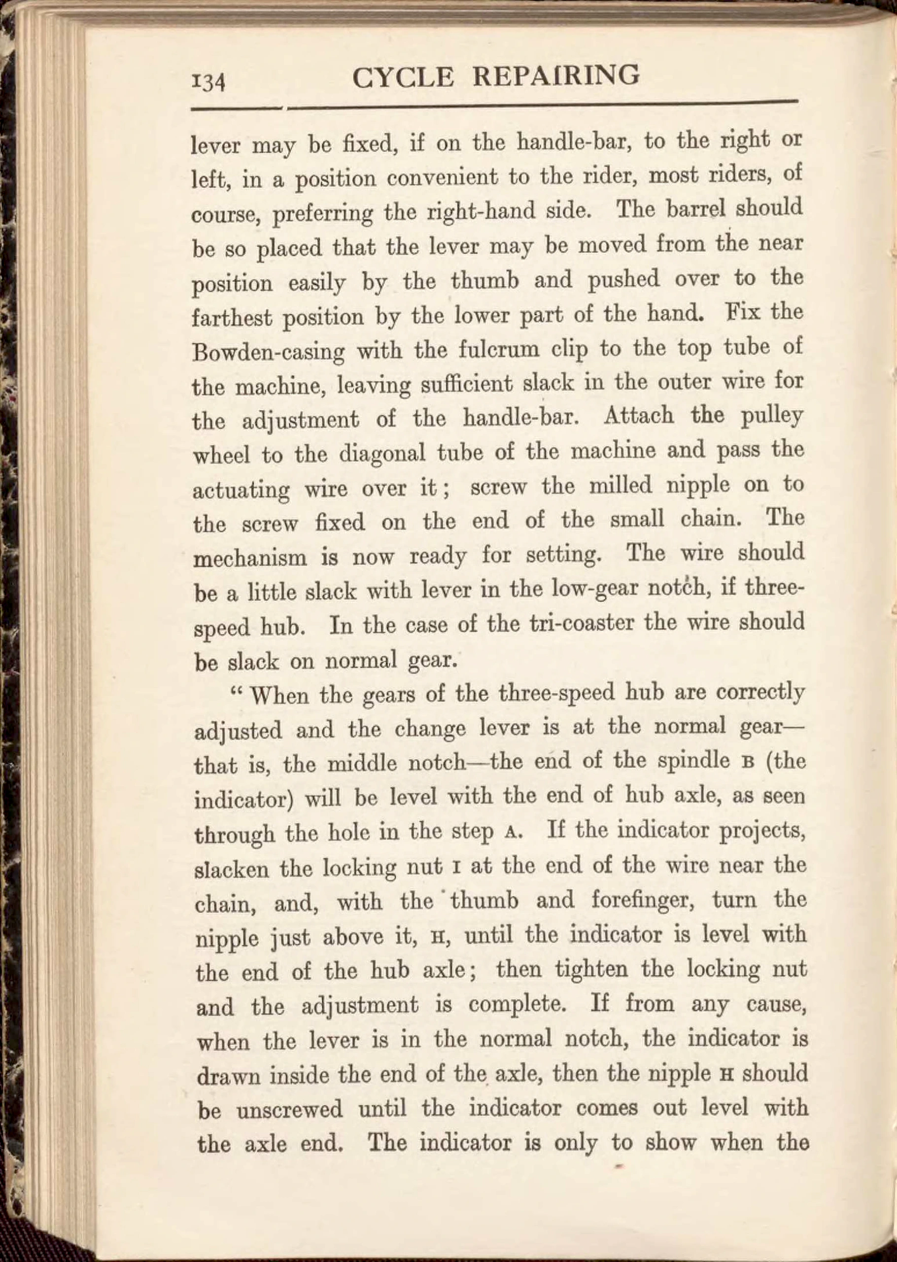 Page 146
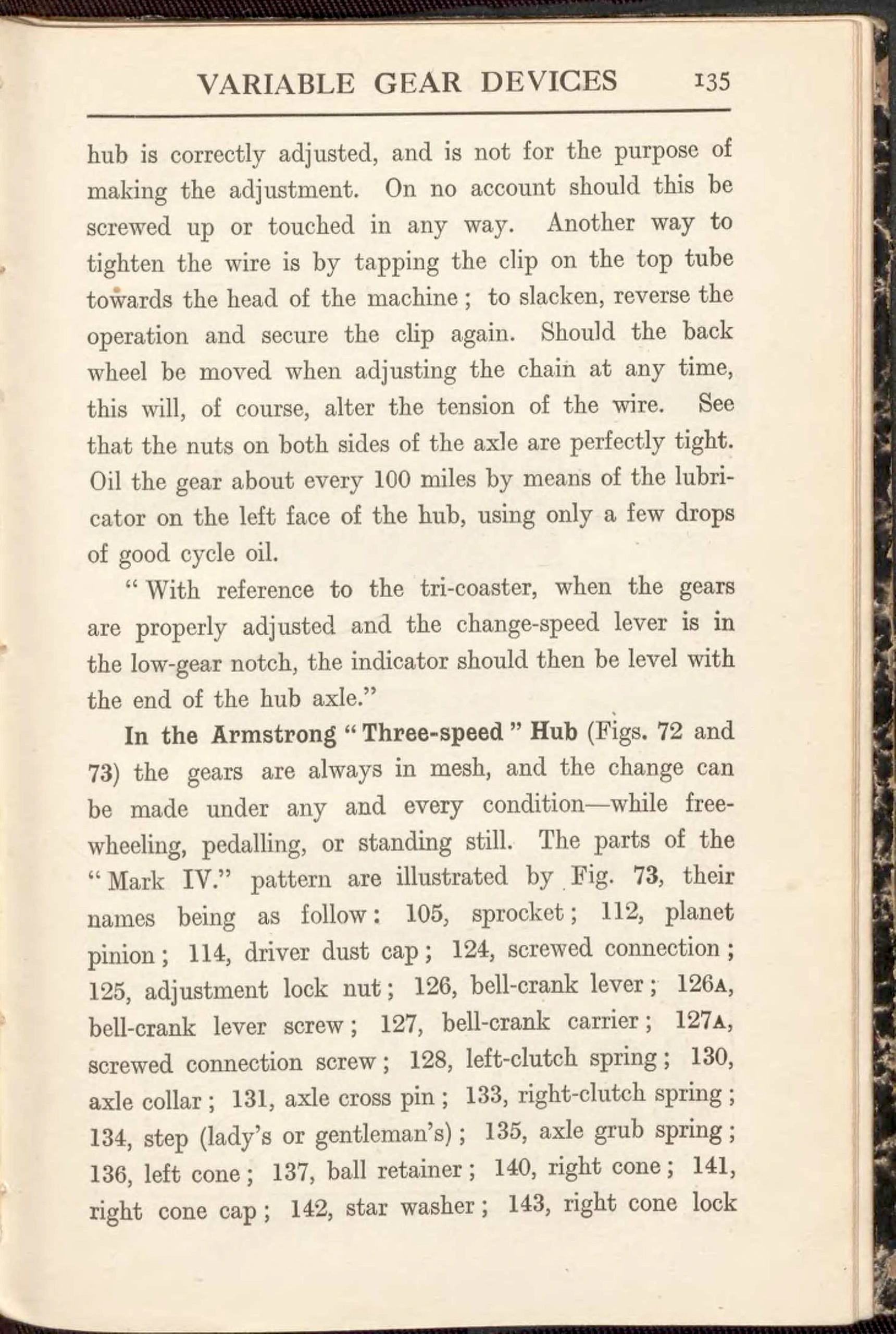 Page 147
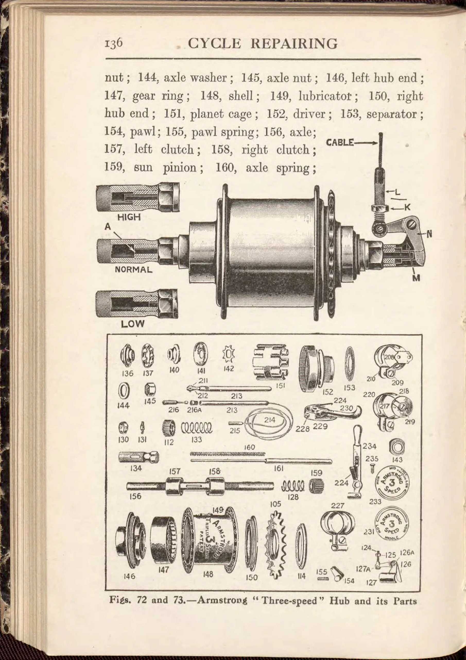 Page 148
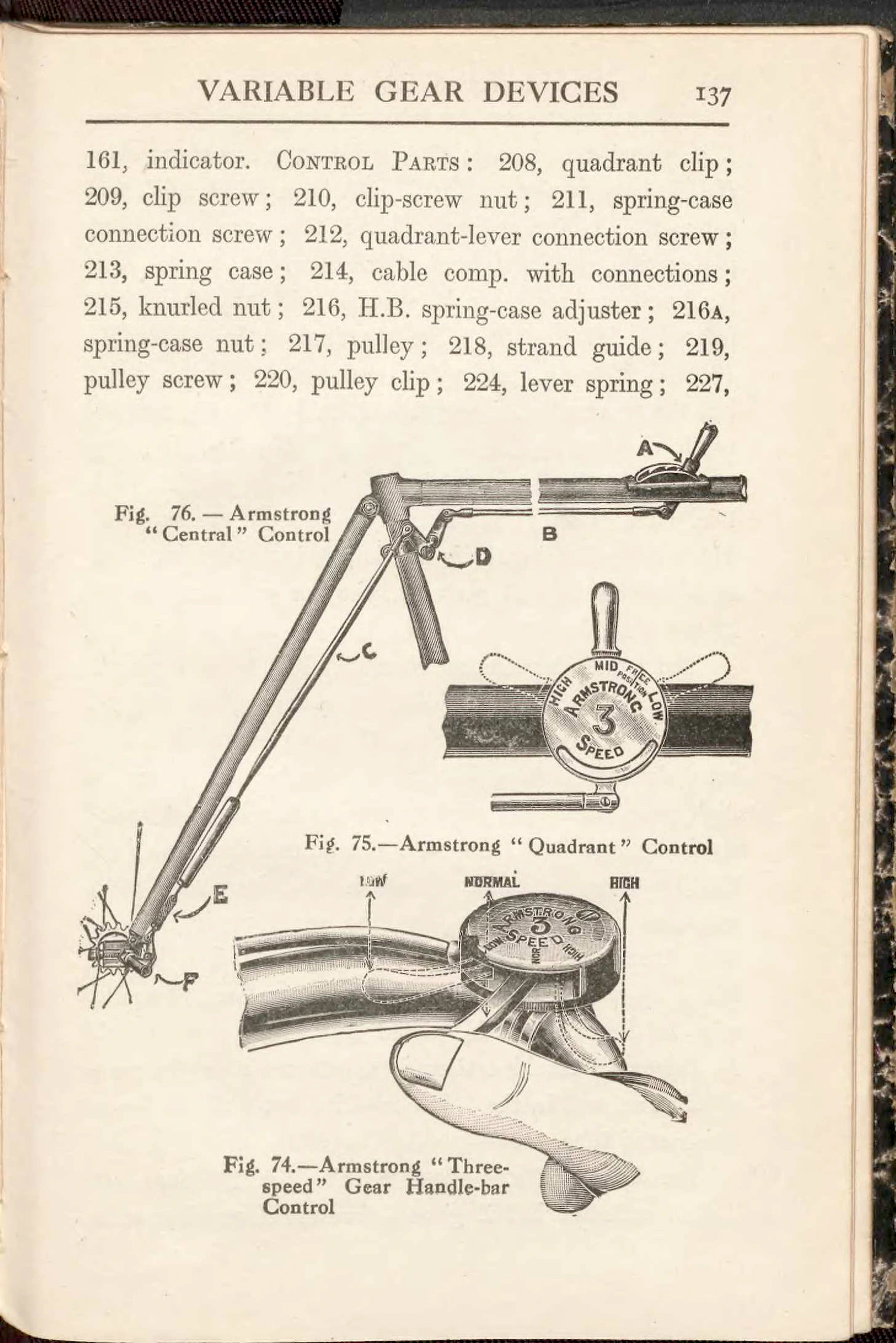 Page 149
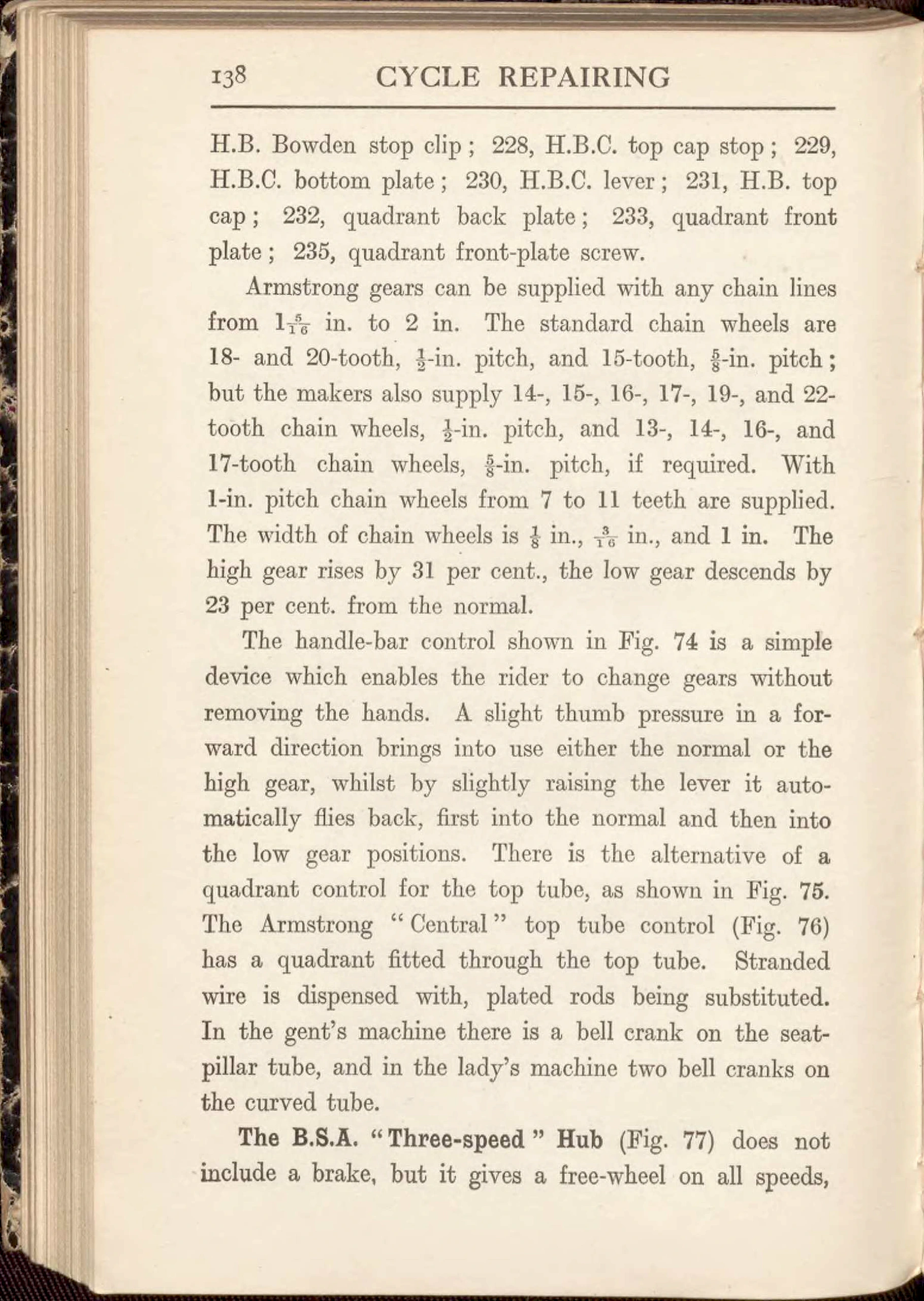 Page 150
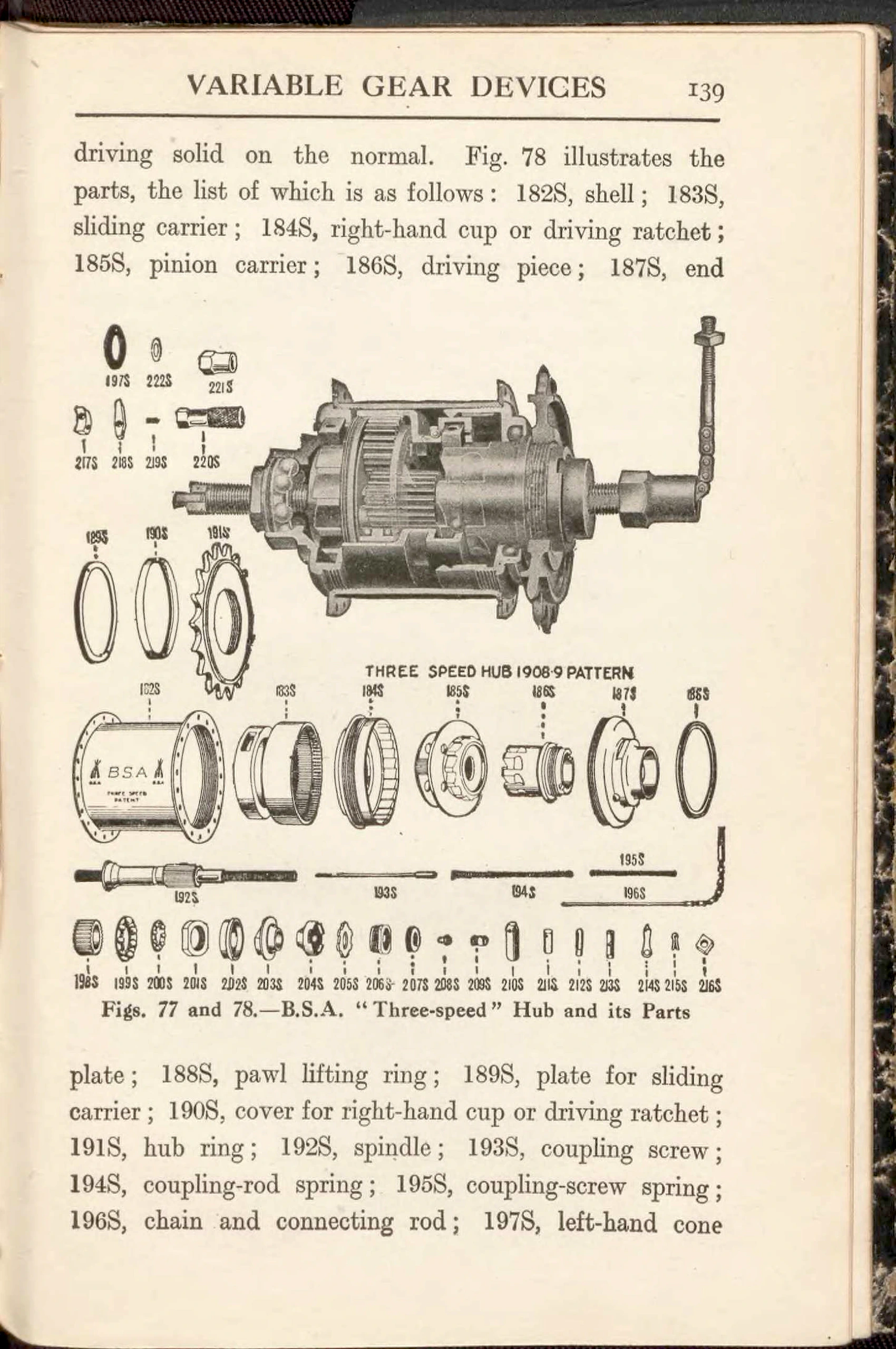 Page 151
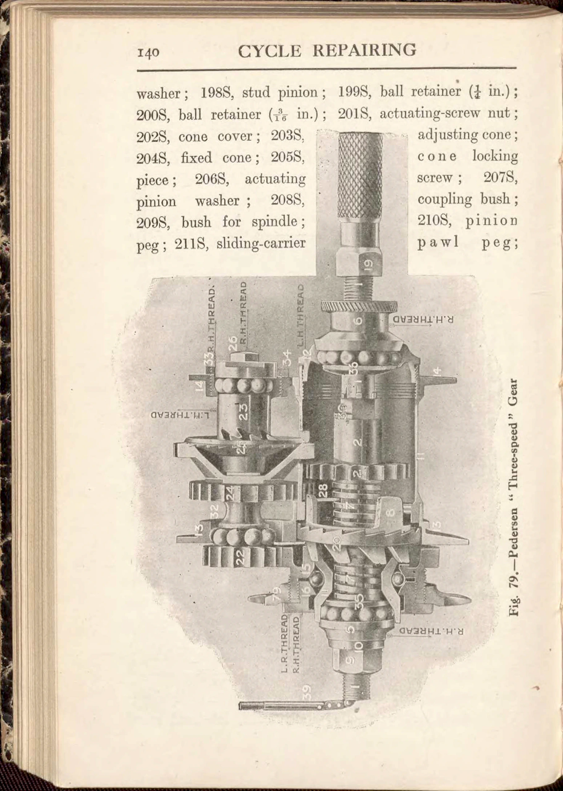 Page 152
 Page 153
 Page 154
 Page 155
 Page 156
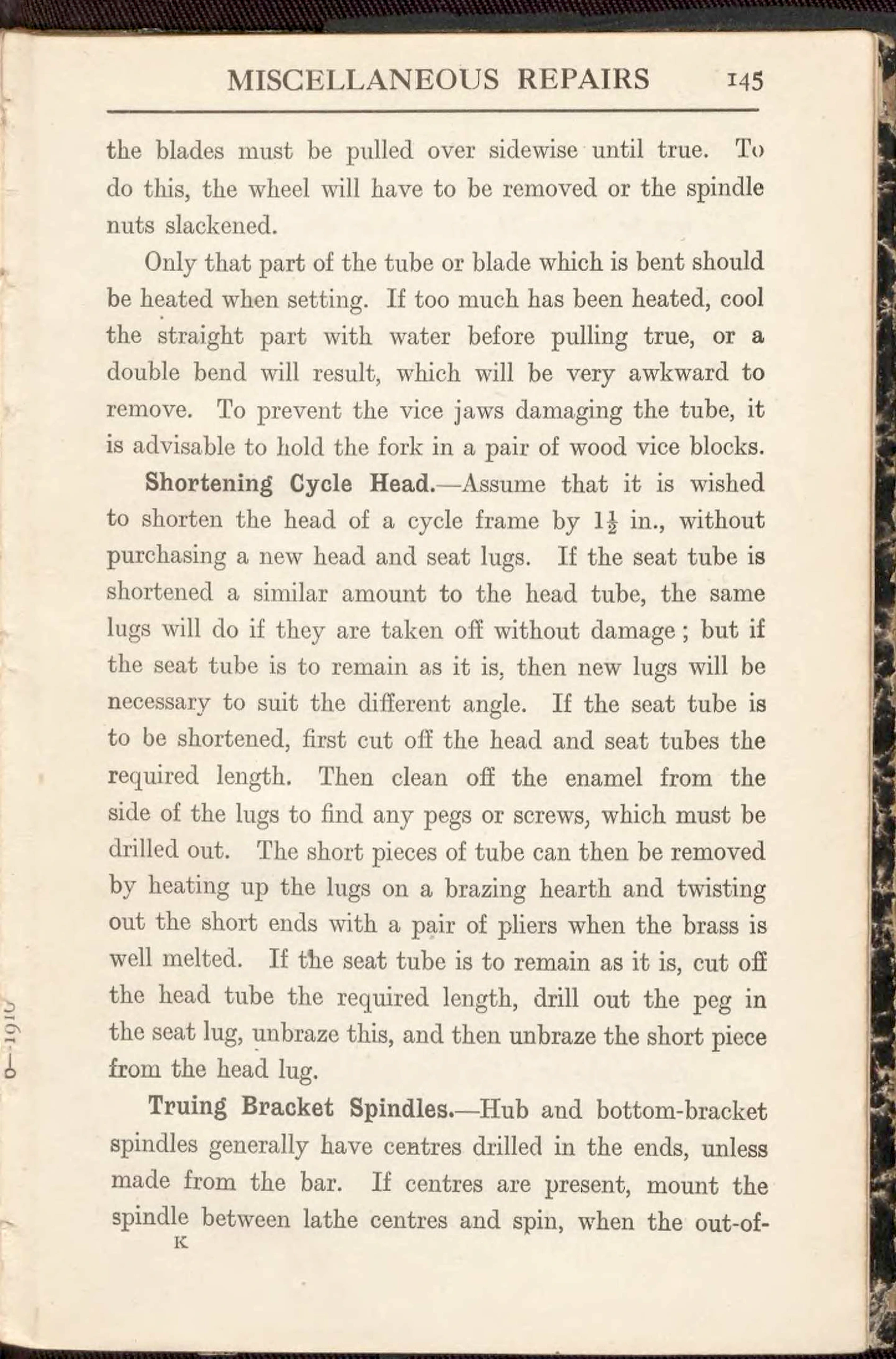 Page 157
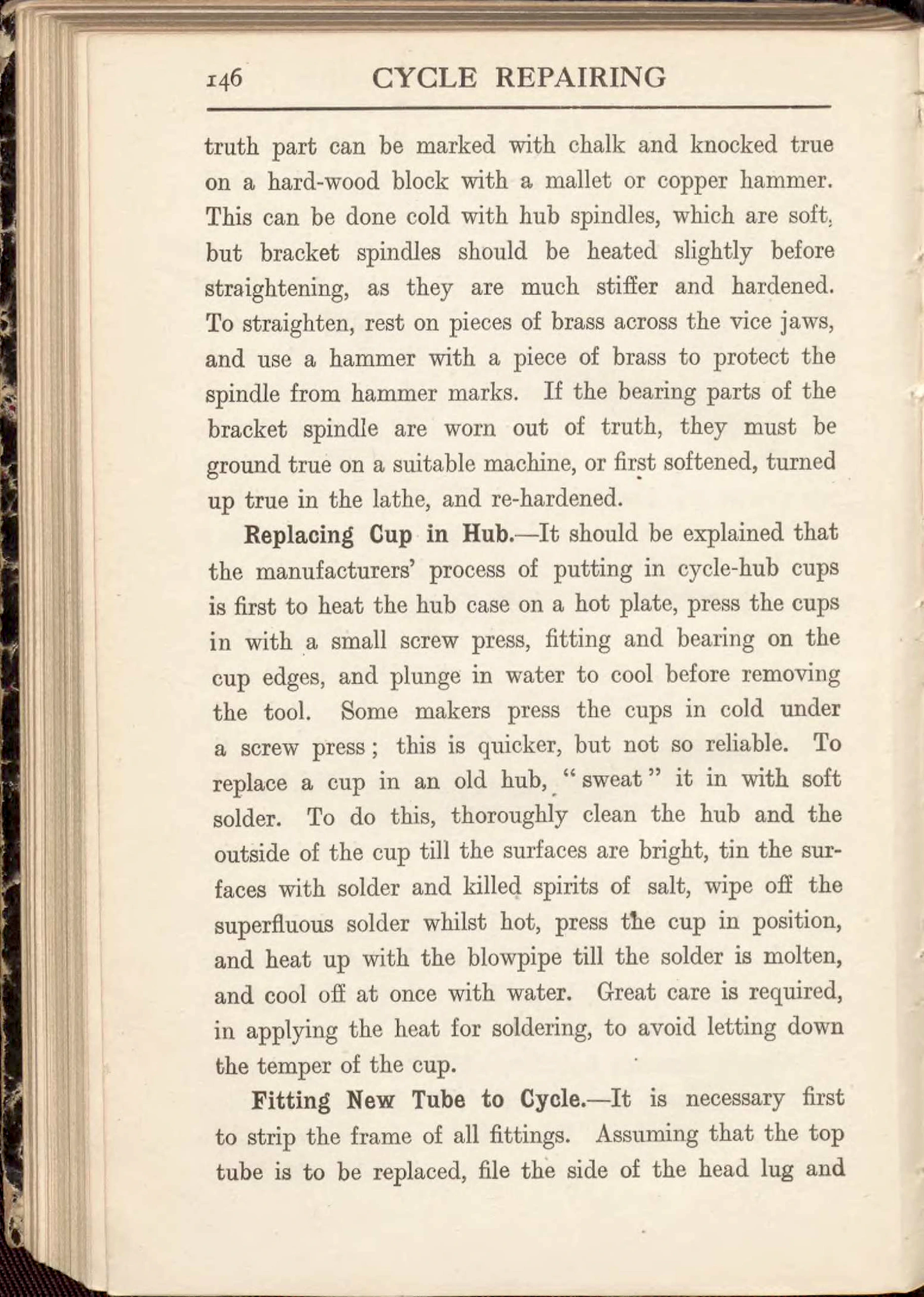 Page 158
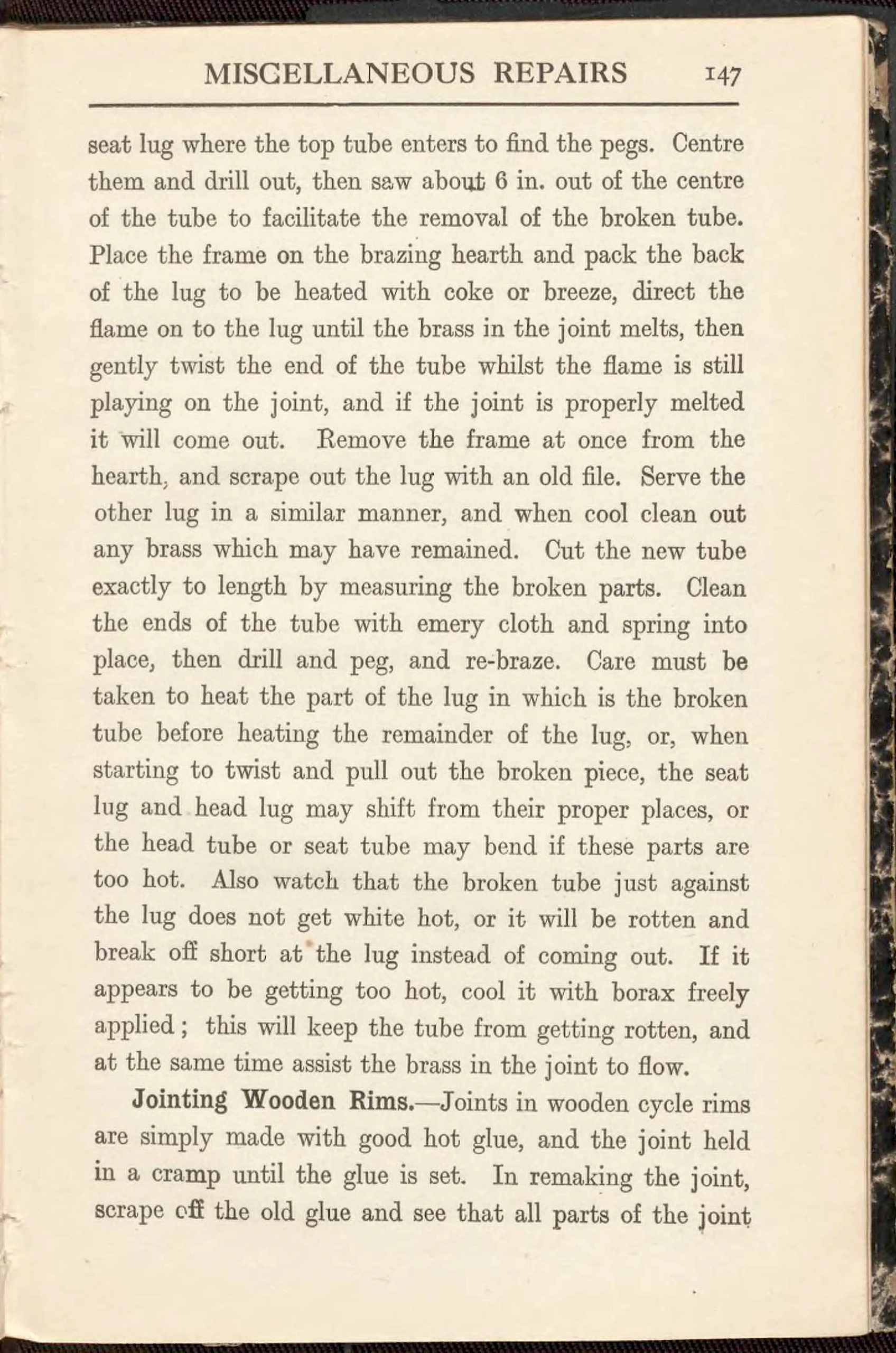 Page 159
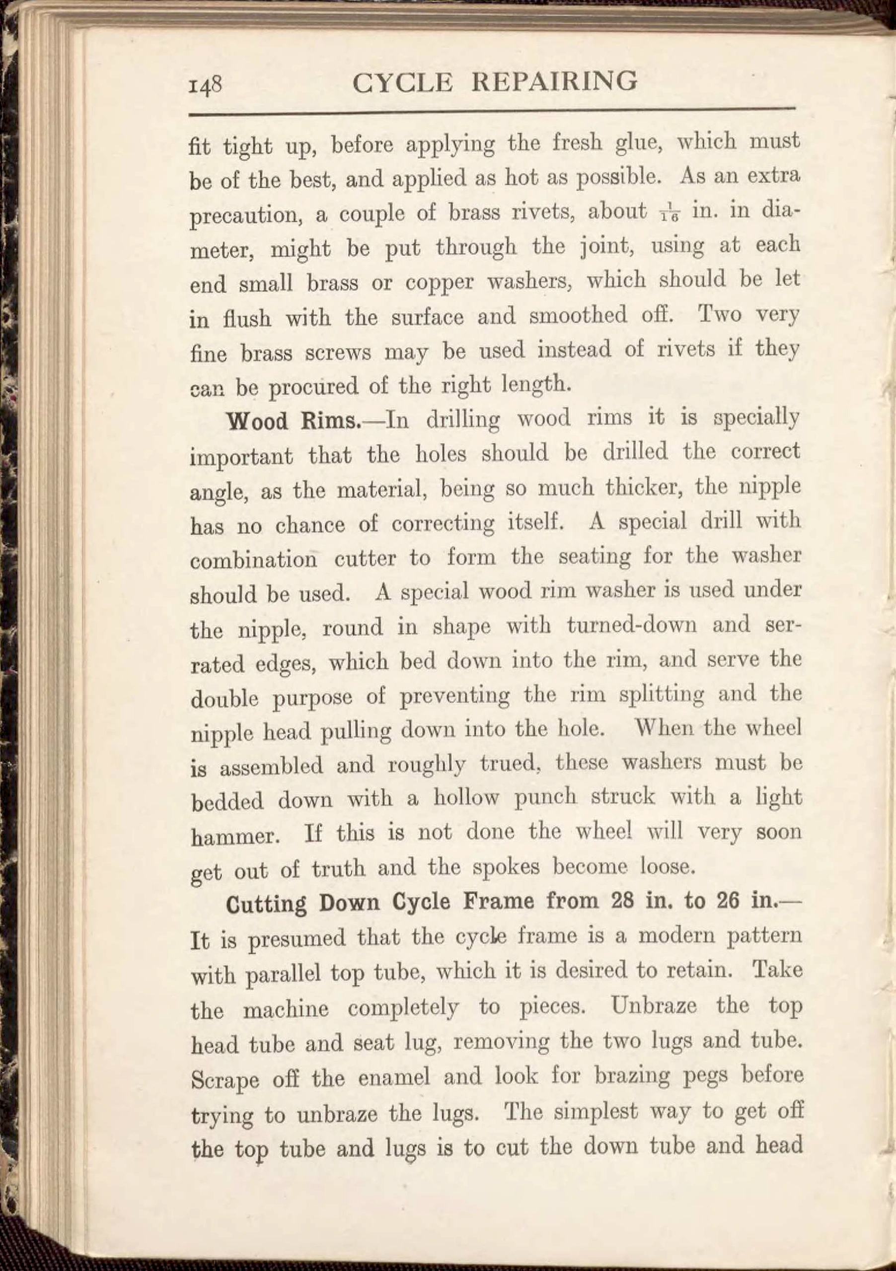 Page 160
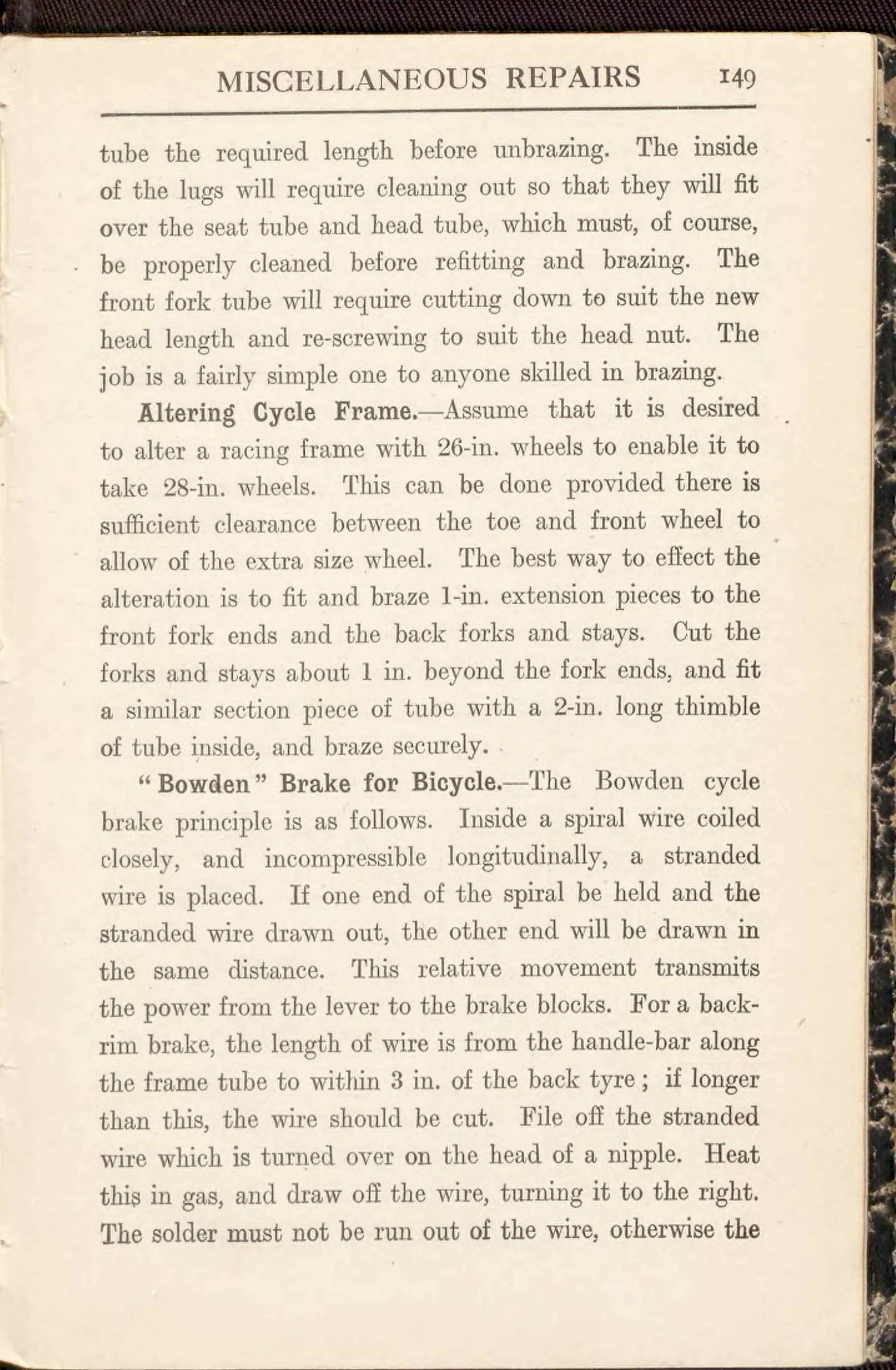 Page 161
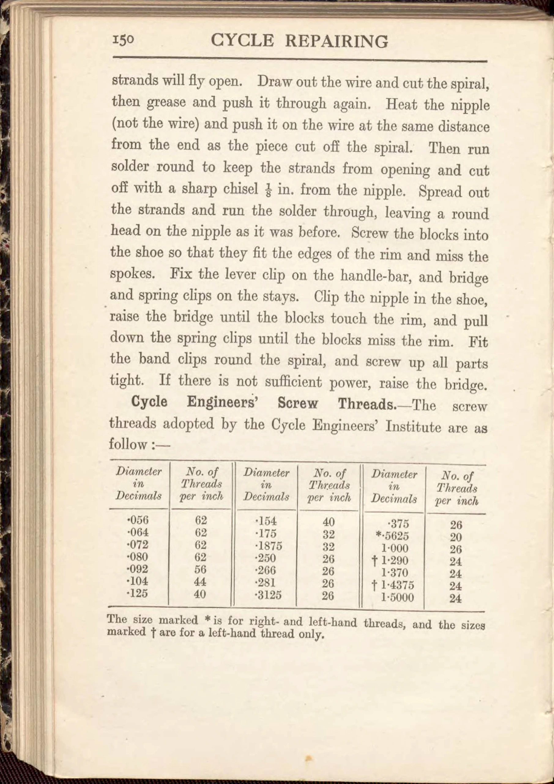 Page 162
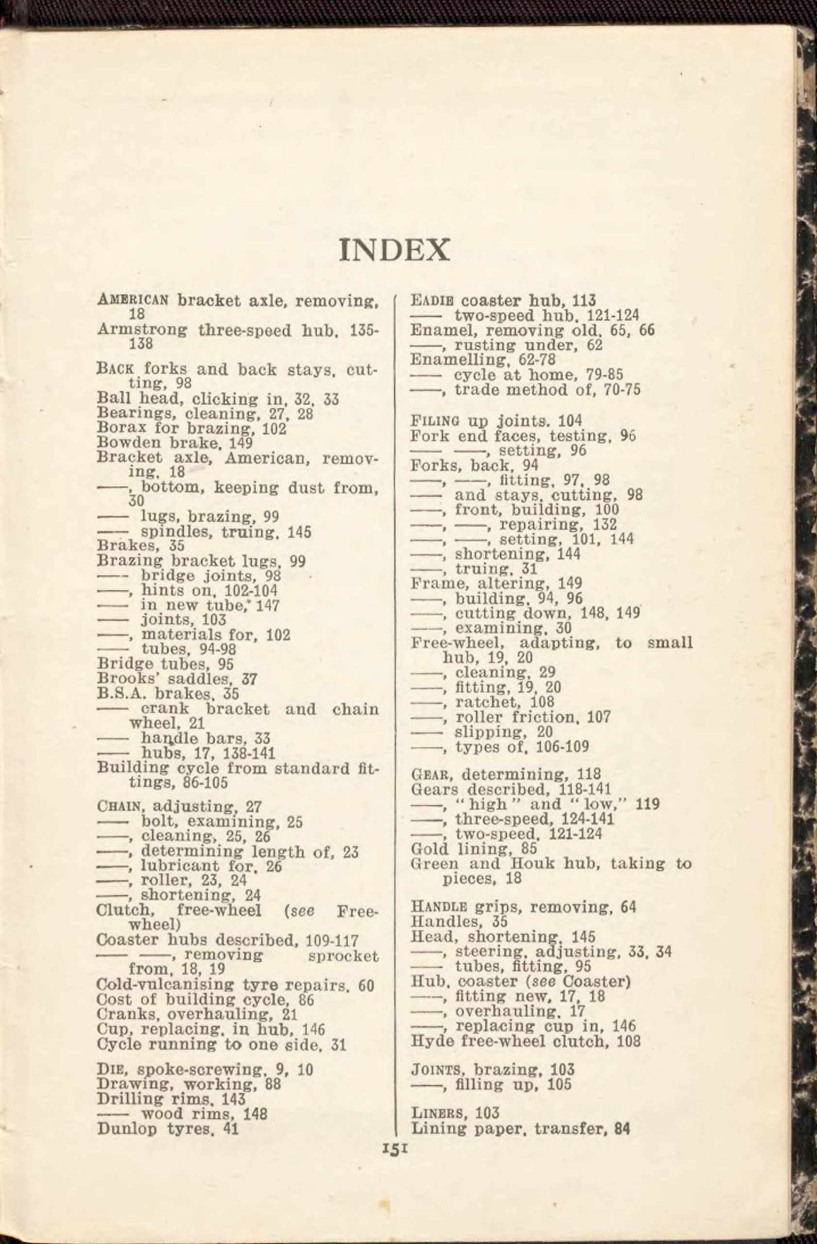 Page 163
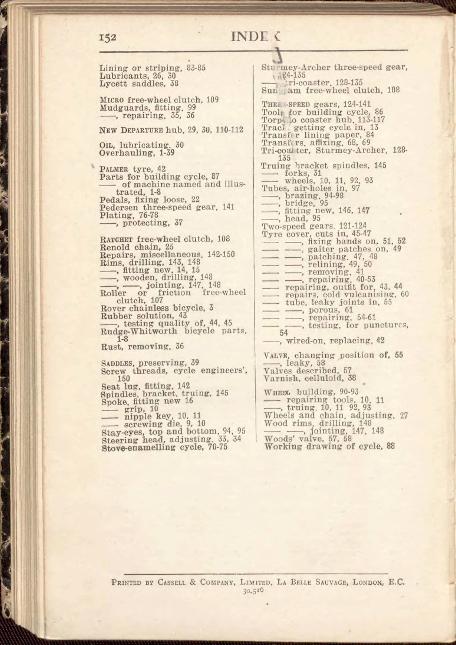 Page 164
 Page 165
 Page 166
 Page 167
 Page 168
| Type | Instructions |
|---|---|
| Year | 1916 |
| Publisher | Cassell and Company, Ltd, London, New York, Toronto and Melbourne |
| Country | England |
| Language | English |
| Pages | 168 |
| Source | DTU Library, Danmarks Tekniske Kulturarv (tekniskkulturarv.dk), which states that most of its collection is in the public domain and may be used for any purpose with the site named; page images are the JPEGs inside DTU's PDF, enlarged for Ebykr. |
| Credit | DTU Bibliotek, Danmarks Tekniske Kulturarv (public domain); Ebykr archive |
| Identifier | Permalink https://tekniskkulturarv.dk/book/dec6aa56-2a37-4558-8ab8-f70b760598dd |
| Transcription | Transcribed by eye |
Reference
Cassell and Company, Ltd, London, New York, Toronto and Melbourne. Cassell's Cycle Repairing and Adjusting, 1916 Reprint: Overhauling a Bicycle, Tire and Tube Repairs, Re-enameling, Freewheels, Coaster Hubs and Variable Gears. 1916. Ebykr, https://ebykr.com/library/cassell-cycle-repairing-and-adjusting-1916/.
Wikipedia
{{cite book |title=Cassell's Cycle Repairing and Adjusting, 1916 Reprint: Overhauling a Bicycle, Tire and Tube Repairs, Re-enameling, Freewheels, Coaster Hubs and Variable Gears |publisher=Cassell and Company, Ltd, London, New York, Toronto and Melbourne |date=1916 |url=https://ebykr.com/library/cassell-cycle-repairing-and-adjusting-1916/ |via=Ebykr |access-date=}}CASSELL'S "WORK" HANDBOOKS CYCLE REPAIRING AND ADJUSTING WITH MANY ILLUSTRATIONS 1/ CYCLE REPAIRING AND ADJUSTING WITH A CHAPTER ON BUILDING A BICYCLE FROM A SET OF PARTS WITH 79 ILLUSTRATIONS CASSELL AND COMPANY, LTD London, New York, Toronto and Melbourne First Edition May 1913. Reprinted March 1914, May 1916. PREFACE This handbook is intended for …
The 168 pages of a Cassell “Work” handbook, Cycle Repairing and Adjusting, first published in May 1913 and reprinted in 1914 and 1916: the complete overhauling of a bicycle, tire and tube repairs, enameling, building a bicycle, freewheels, coaster hubs and variable gears, with an index.
— Page 1 (front cover) —
CASSELL’S “WORK” HANDBOOKS
CYCLE REPAIRING AND ADJUSTING
WITH MANY ILLUSTRATIONS
1/
[The red front cover of Cycle Repairing and Adjusting, Cassell’s “Work” Handbooks, with a photograph of a man holding a bicycle wheel above an upturned bicycle frame on a workbench. The price appears in a worn blue panel at the top right. Later marks: a gilt ornament on the leather spine strip, a pen number below the title and a handwritten shelf number running up the lower left of the cover.]
— Page 2 (inside front cover) —
[The inside front cover with a small octagonal bookplate in Danish script lettering at the center of the page, and a strip of marbled paper along the left edge. Later marks: a blue crayon number at the top left struck through and underlined in pencil, a blue crayon number and a pencil number at the lower left.]
[A blank flyleaf with no printing, toned cream with a darker rectangular area and a pale diamond-shaped patch at the center of the page. No handwriting, stamps or labels are visible.]
[A blank flyleaf with no printing, toned cream with a faint pale diamond-shaped patch at the center and a strip of marbled paper along the left edge. No handwriting, stamps or labels are visible.]
— Page 5 —
CYCLE REPAIRING
AND ADJUSTING
WITH A CHAPTER ON
BUILDING A BICYCLE
FROM A SET OF PARTS
WITH 79 ILLUSTRATIONS
CASSELL AND COMPANY, LTD
London, New York, Toronto and Melbourne
[The title page of Cycle Repairing and Adjusting, with a chapter on building a bicycle from a set of parts, set within a double ruled border, with the publisher Cassell and Company, Ltd. Later marks: a green crayon line under the first word of the title and a faint pencil cross above the border.]
— Page 6 —
First Edition May 1913.
Reprinted March 1914, May 1916.
[The imprint page, otherwise blank, with a two-line edition notice in small type at the center and a strip of marbled paper along the left edge. No handwriting, stamps or labels are visible.]
— Page 7 —
PREFACE
This handbook is intended for the use of cyclists and repairers generally, and provides practical and easily-understood information on the complete overhauling of a cycle and on the execution of a great variety of repairs to the machine and its tyres. It describes how to prepare cycles for re-enamelling and re-plating, gives full instructions on re-enamelling a cycle at home, and explains how to build a bicycle from a set of standard parts. In addition, it describes and illustrates a large number of free-wheel clutches, coaster hubs, and variable gear devices. Should any reader need further information on any matter herein discussed, I shall be happy to give it him through the “Questions and Answers” columns of my journal.
The Editor “Work.”
[The Preface of Cycle Repairing and Adjusting, one paragraph of text signed by the Editor of “Work”, on an otherwise plain page with no folio printed. No handwriting, stamps or labels are visible.]
[A blank page with no printing, the back of the Preface leaf, with the faint show-through of the Preface text from the other side and a strip of marbled paper along the left edge. No handwriting, stamps or labels are visible.]
— Page 9 —
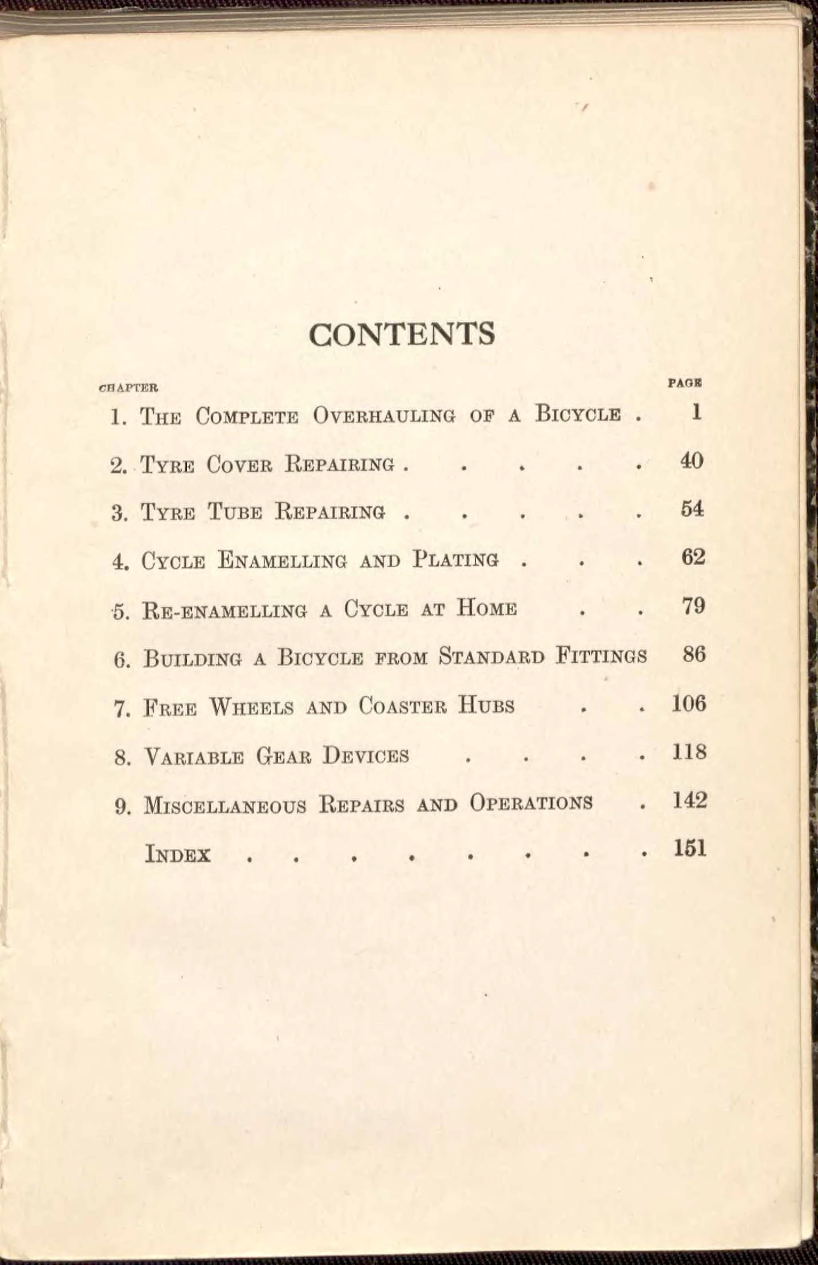
CONTENTS
CHAPTER PAGE
1. The Complete Overhauling of a Bicycle …. 1
2. Tyre Cover Repairing …. 40
3. Tyre Tube Repairing …. 54
4. Cycle Enamelling and Plating …. 62
5. Re-enamelling a Cycle at Home …. 79
6. Building a Bicycle from Standard Fittings 86
7. Free Wheels and Coaster Hubs …. 106
8. Variable Gear Devices …. 118
9. Miscellaneous Repairs and Operations …. 142
Index …. 151
[The Contents page of Cycle Repairing and Adjusting, listing nine numbered chapters and the Index with their page numbers, set with dot leaders. No folio is printed on the page. No handwriting, stamps or labels are visible.]
[A blank page with no printing, the back of the Contents leaf, with the faint show-through of the Contents lines from the other side and a strip of marbled paper along the left edge. No handwriting, stamps or labels are visible.]
— Page 11 —
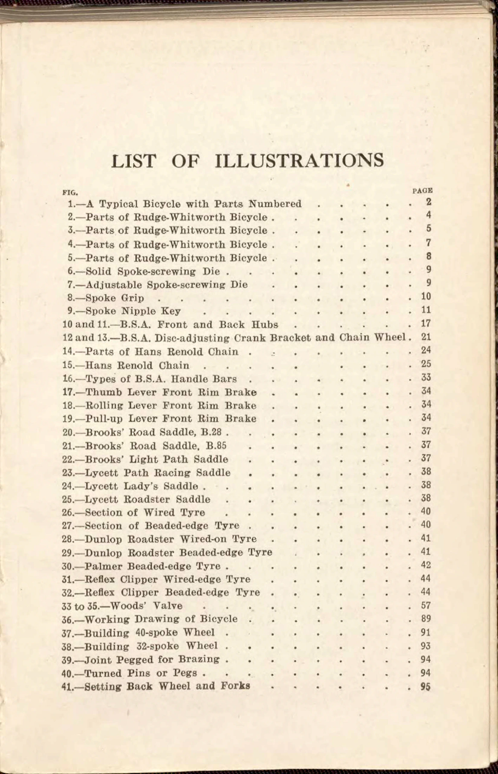
LIST OF ILLUSTRATIONS
FIG. PAGE
1.—A Typical Bicycle with Parts Numbered …. 2
2.—Parts of Rudge-Whitworth Bicycle …. 4
3.—Parts of Rudge-Whitworth Bicycle …. 5
4.—Parts of Rudge-Whitworth Bicycle …. 7
5.—Parts of Rudge-Whitworth Bicycle …. 8
6.—Solid Spoke-screwing Die …. 9
7.—Adjustable Spoke-screwing Die …. 9
8.—Spoke Grip …. 10
9.—Spoke Nipple Key …. 11
10 and 11.—B.S.A. Front and Back Hubs …. 17
12 and 13.—B.S.A. Disc-adjusting Crank Bracket and Chain Wheel. 21
14.—Parts of Hans Renold Chain …. 24
15.—Hans Renold Chain …. 25
16.—Types of B.S.A. Handle Bars …. 33
17.—Thumb Lever Front Rim Brake …. 34
18.—Rolling Lever Front Rim Brake …. 34
19.—Pull-up Lever Front Rim Brake …. 34
20.—Brooks’ Road Saddle, B.28 …. 37
21.—Brooks’ Road Saddle, B.85 …. 37
22.—Brooks’ Light Path Saddle …. 37
23.—Lycett Path Racing Saddle …. 38
24.—Lycett Lady’s Saddle …. 38
25.—Lycett Roadster Saddle …. 38
26.—Section of Wired Tyre …. 40
27.—Section of Beaded-edge Tyre …. 40
28.—Dunlop Roadster Wired-on Tyre …. 41
29.—Dunlop Roadster Beaded-edge Tyre …. 41
30.—Palmer Beaded-edge Tyre …. 42
31.—Reflex Clipper Wired-edge Tyre …. 44
32.—Reflex Clipper Beaded-edge Tyre …. 44
33 to 35.—Woods’ Valve …. 57
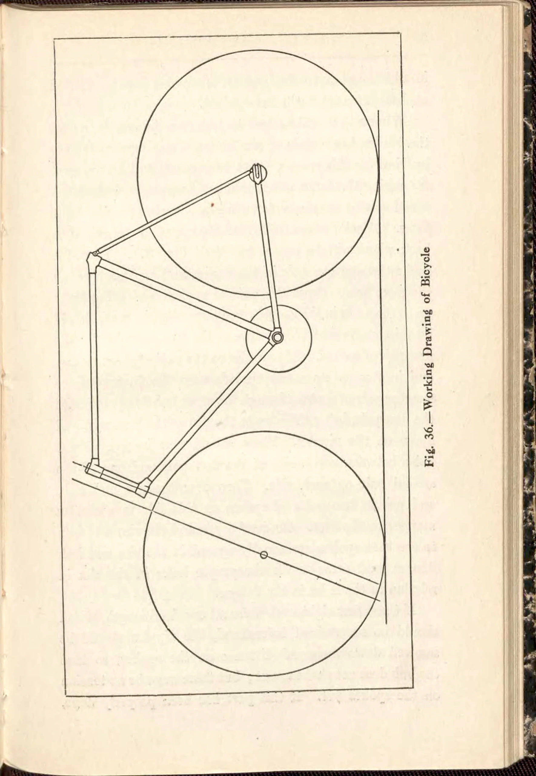
36.—Working Drawing of Bicycle …. 89
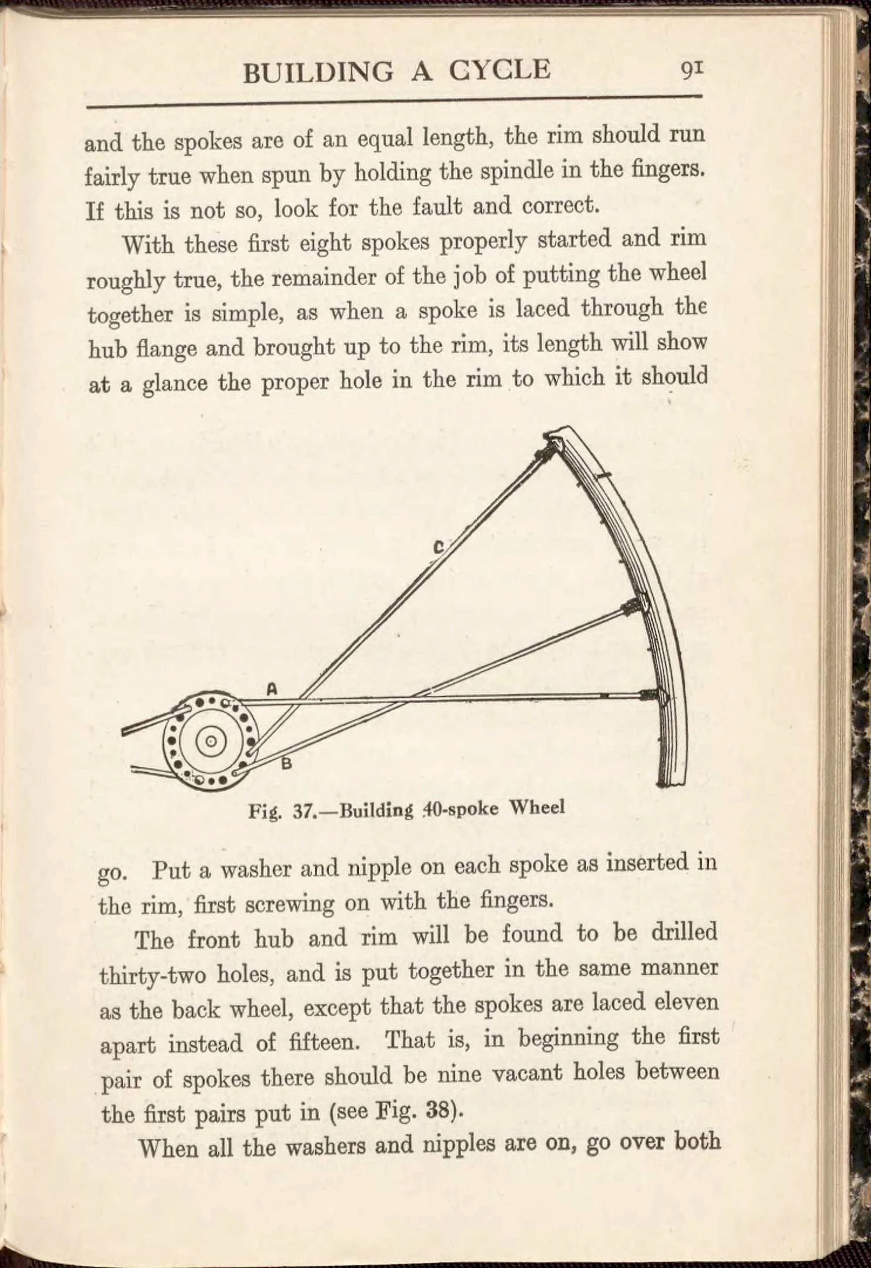
37.—Building 40-spoke Wheel …. 91
38.—Building 32-spoke Wheel …. 93
39.—Joint Pegged for Brazing …. 94
40.—Turned Pins or Pegs …. 94
41.—Setting Back Wheel and Forks …. 95
[The first page of the List of Illustrations in Cycle Repairing and Adjusting, giving figures 1 to 41 with their page numbers, set with dot leaders. The figures include a Rudge-Whitworth bicycle, B.S.A. parts, saddles, tires and wheel building. No folio is printed on the page. No handwriting, stamps or labels are visible.]
— Page 12 —
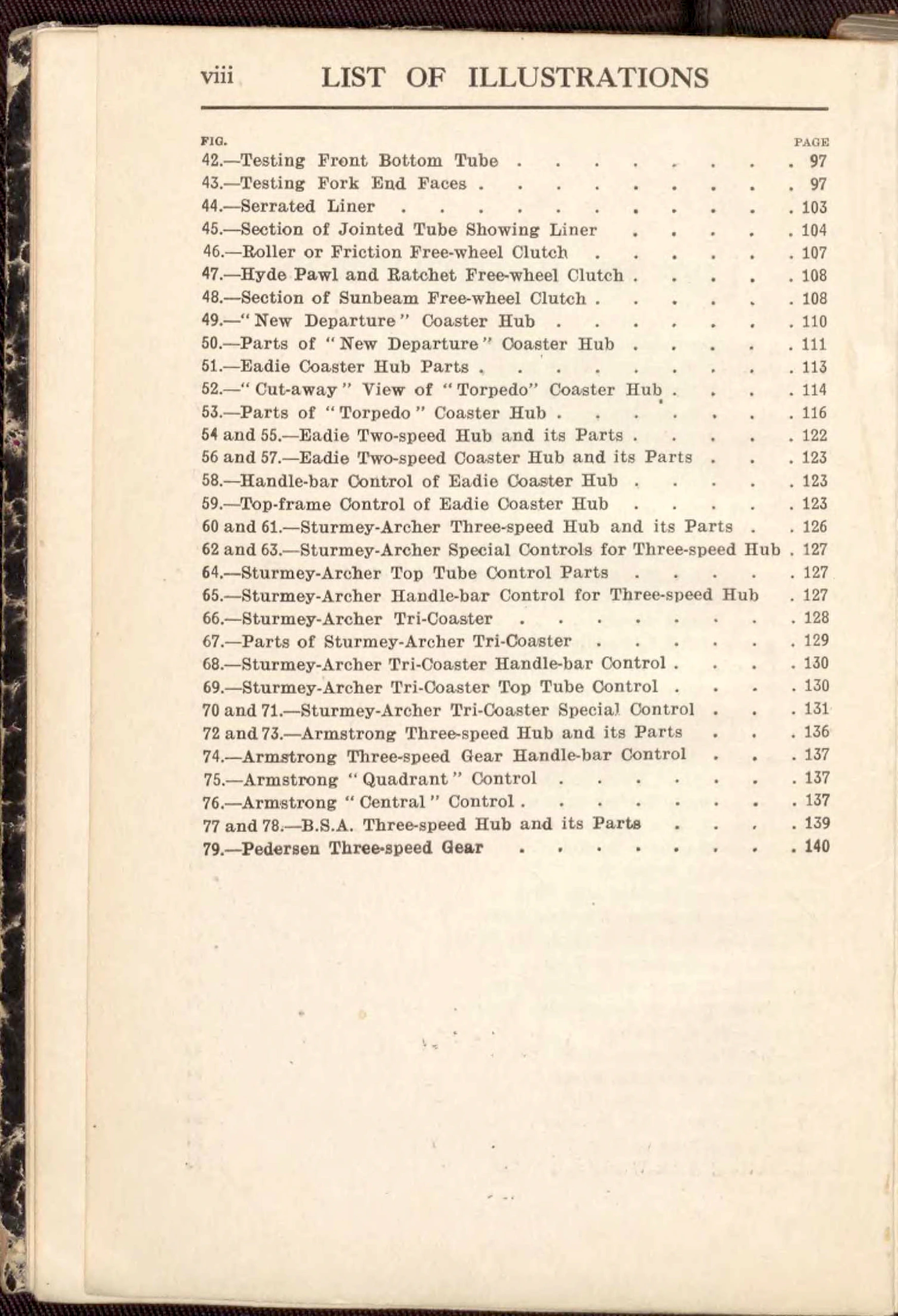
viii LIST OF ILLUSTRATIONS
FIG. PAGE
42.—Testing Front Bottom Tube …. 97
43.—Testing Fork End Faces …. 97
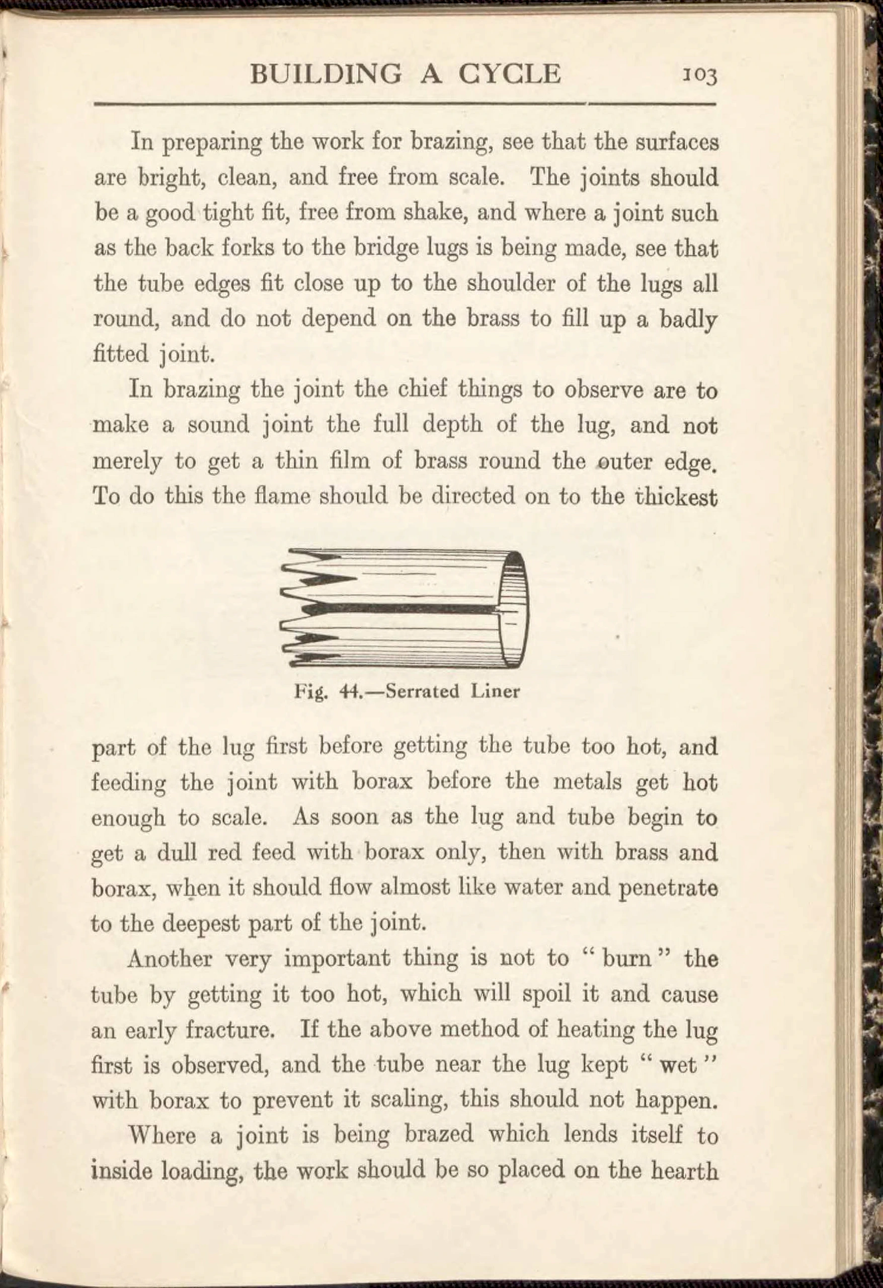
44.—Serrated Liner …. 103
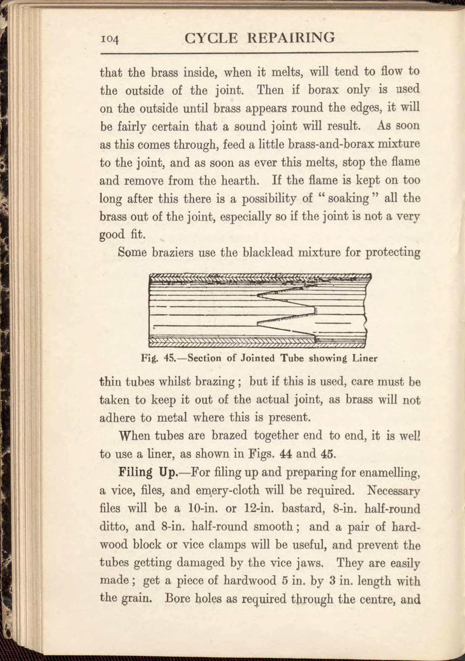
45.—Section of Jointed Tube Showing Liner …. 104
46.—Roller or Friction Free-wheel Clutch …. 107
47.—Hyde Pawl and Ratchet Free-wheel Clutch …. 108
48.—Section of Sunbeam Free-wheel Clutch …. 108
49.—”New Departure” Coaster Hub …. 110
50.—Parts of “New Departure” Coaster Hub …. 111
51.—Eadie Coaster Hub Parts …. 113
52.—”Cut-away” View of “Torpedo” Coaster Hub …. 114
53.—Parts of “Torpedo” Coaster Hub …. 116
54 and 55.—Eadie Two-speed Hub and its Parts …. 122
56 and 57.—Eadie Two-speed Coaster Hub and its Parts …. 123
58.—Handle-bar Control of Eadie Coaster Hub …. 123
59.—Top-frame Control of Eadie Coaster Hub …. 123
60 and 61.—Sturmey-Archer Three-speed Hub and its Parts …. 126
62 and 63.—Sturmey-Archer Special Controls for Three-speed Hub . 127
64.—Sturmey-Archer Top Tube Control Parts …. 127
65.—Sturmey-Archer Handle-bar Control for Three-speed Hub . 127
66.—Sturmey-Archer Tri-Coaster …. 128
67.—Parts of Sturmey-Archer Tri-Coaster …. 129
68.—Sturmey-Archer Tri-Coaster Handle-bar Control …. 130
69.—Sturmey-Archer Tri-Coaster Top Tube Control …. 130
70 and 71.—Sturmey-Archer Tri-Coaster Special Control …. 131
72 and 73.—Armstrong Three-speed Hub and its Parts …. 136
74.—Armstrong Three-speed Gear Handle-bar Control …. 137
75.—Armstrong “Quadrant” Control …. 137
76.—Armstrong “Central” Control …. 137
77 and 78.—B.S.A. Three-speed Hub and its Parts …. 139
79.—Pedersen Three-speed Gear …. 140
[The second page of the List of Illustrations in Cycle Repairing and Adjusting, giving figures 42 to 79 with their page numbers, set with dot leaders. The figures include freewheel clutches, coaster hubs and Sturmey-Archer, Armstrong and Pedersen gears. A strip of marbled paper runs along the left edge. No handwriting, stamps or labels are visible.]
— Page 13 —
CYCLE REPAIRING
CHAPTER I
The Complete Overhauling of a Bicycle
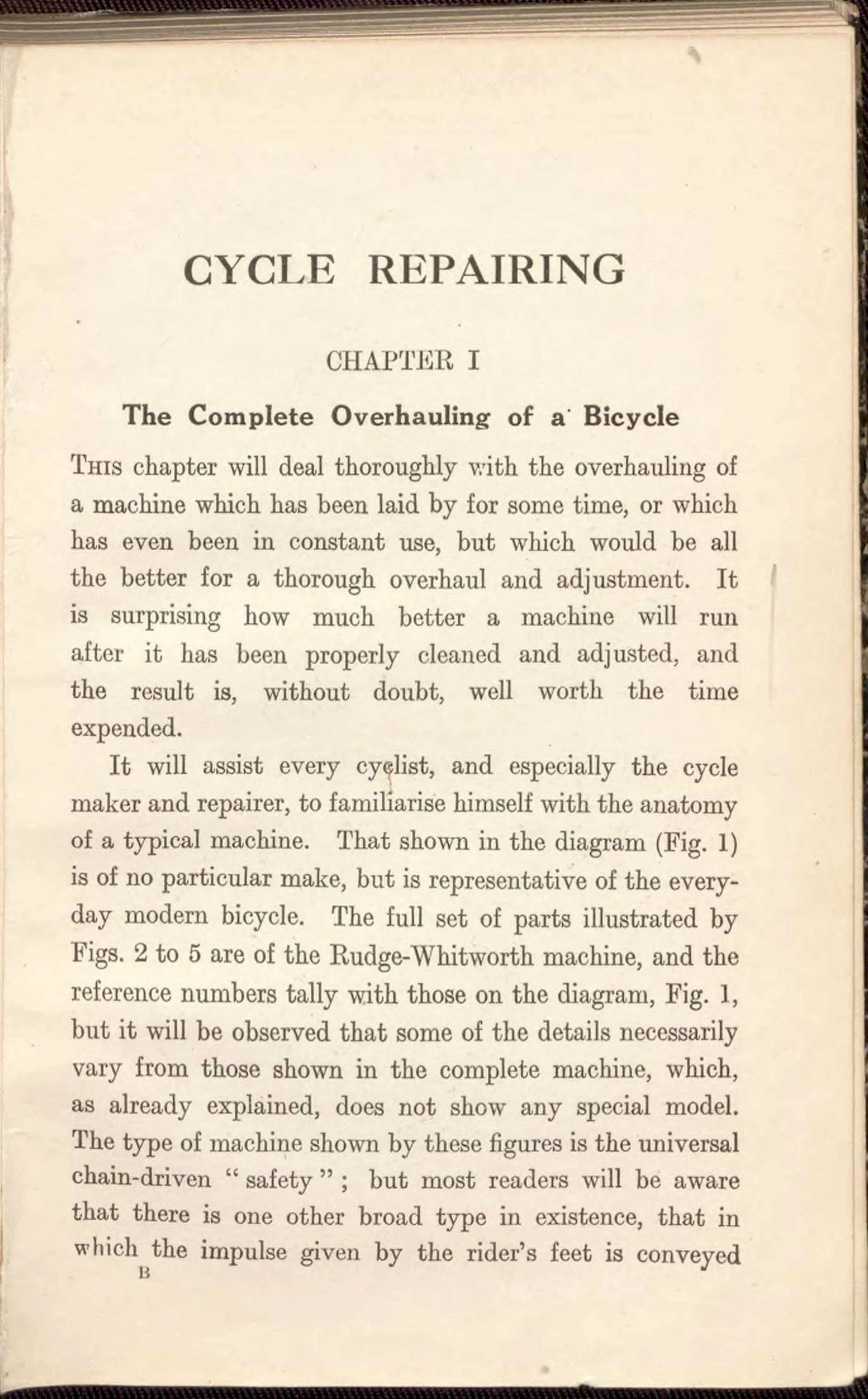
This chapter will deal thoroughly with the overhauling of a machine which has been laid by for some time, or which has even been in constant use, but which would be all the better for a thorough overhaul and adjustment. It is surprising how much better a machine will run after it has been properly cleaned and adjusted, and the result is, without doubt, well worth the time expended.
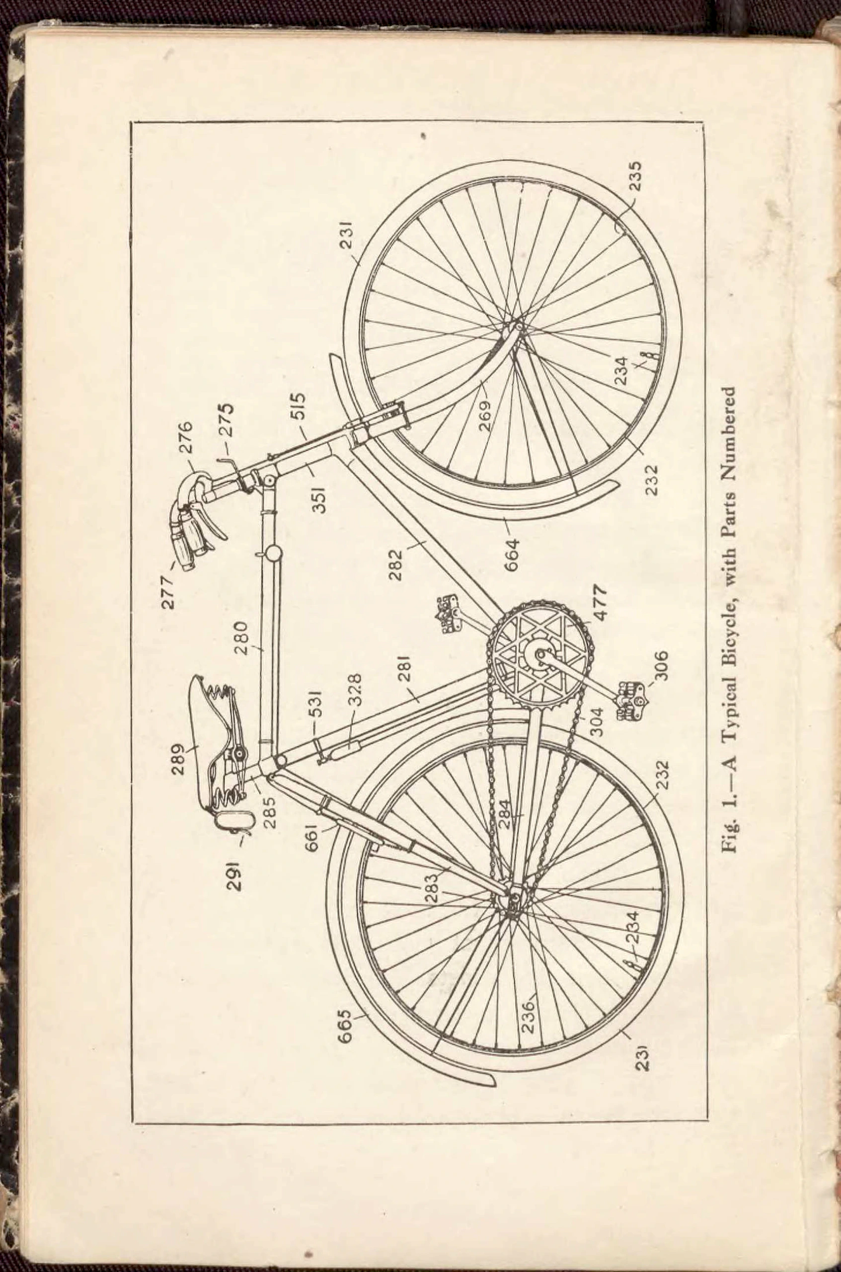
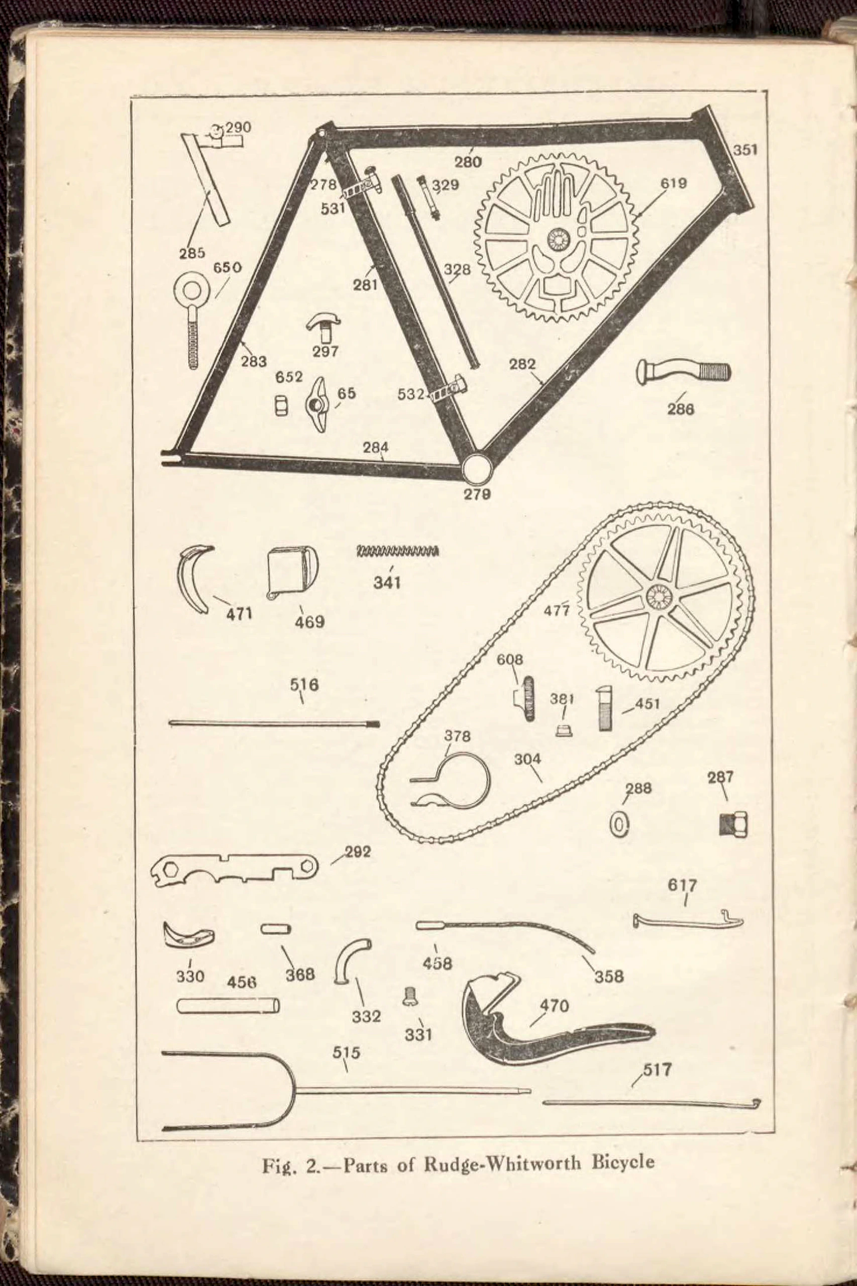
It will assist every cyclist, and especially the cycle maker and repairer, to familiarise himself with the anatomy of a typical machine. That shown in the diagram (Fig. 1) is of no particular make, but is representative of the every-day modern bicycle. The full set of parts illustrated by Figs. 2 to 5 are of the Rudge-Whitworth machine, and the reference numbers tally with those on the diagram, Fig. 1, but it will be observed that some of the details necessarily vary from those shown in the complete machine, which, as already explained, does not show any special model. The type of machine shown by these figures is the universal chain-driven “safety”; but most readers will be aware that there is one other broad type in existence, that in which the impulse given by the rider’s feet is conveyed
[The opening page of Chapter I, “The Complete Overhauling of a Bicycle”, under the heading “Cycle Repairing”, with two paragraphs of text. A printer’s signature letter B is set at the foot of the text; the printed page has no folio number, and the dark edge of the book board shows along the top and right edges of the scan.]
— Page 14 —
Fig. 1.—A Typical Bicycle, with Parts Numbered
Callouts: 289 277 276 291 275 280 285 515 351 661 531 328 665 231 282 281 283 269 664 284 236 477 304 306 234 235 231 234 232 232
[A man’s bicycle with a diamond frame, a saddle, dropped handlebars, mudguards, a chain and pedals, drawn in outline with reference numbers on its parts, in Fig. 1, “A Typical Bicycle, with Parts Numbered”. The plate is printed sideways on the leaf, so the caption reads from bottom to top, and it has no printed folio.]
— Page 15 —
OVERHAULING A BICYCLE 3
to the driving wheel at the back, not by cranks and chains, but by shafts and bevel gears. A typical machine of this type is the “Rover Chainless,” which has many special points of interest.
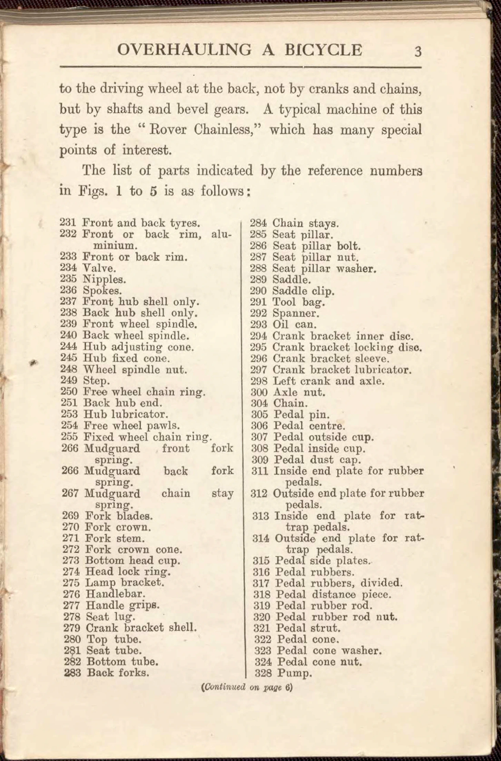
The list of parts indicated by the reference numbers in Figs. 1 to 5 is as follows:
231 Front and back tyres.
232 Front or back rim, aluminium.
233 Front or back rim.
234 Valve.
235 Nipples.
236 Spokes.
237 Front hub shell only.
238 Back hub shell only.
239 Front wheel spindle.
240 Back wheel spindle.
244 Hub adjusting cone.
245 Hub fixed cone.
248 Wheel spindle nut.
249 Step.
250 Free wheel chain ring.
251 Back hub end.
253 Hub lubricator.
254 Free wheel pawls.
255 Fixed wheel chain ring.
266 Mudguard front fork spring.
266 Mudguard back fork spring.
267 Mudguard chain stay spring.
269 Fork blades.
270 Fork crown.
271 Fork stem.
272 Fork crown cone.
273 Bottom head cup.
274 Head lock ring.
275 Lamp bracket.
276 Handlebar.
277 Handle grips.
278 Seat lug.
279 Crank bracket shell.
280 Top tube.
281 Seat tube.
282 Bottom tube.
283 Back forks.
284 Chain stays.
285 Seat pillar.
286 Seat pillar bolt.
287 Seat pillar nut.
288 Seat pillar washer.
289 Saddle.
290 Saddle clip.
291 Tool bag.
292 Spanner.
293 Oil can.
294 Crank bracket inner disc.
295 Crank bracket locking disc.
296 Crank bracket sleeve.
297 Crank bracket lubricator.
298 Left crank and axle.
300 Axle nut.
304 Chain.
305 Pedal pin.
306 Pedal centre.
307 Pedal outside cup.
308 Pedal inside cup.
309 Pedal dust cap.
311 Inside end plate for rubber pedals.
312 Outside end plate for rubber pedals.
313 Inside end plate for rat-trap pedals.
314 Outside end plate for rat-trap pedals.
315 Pedal side plates.
316 Pedal rubbers.
317 Pedal rubbers, divided.
318 Pedal distance piece.
319 Pedal rubber rod.
320 Pedal rubber rod nut.
321 Pedal strut.
322 Pedal cone.
323 Pedal cone washer.
324 Pedal cone nut.
328 Pump.
(Continued on page 6)
[A page of text and a two-column numbered parts list, numbers 231 to 328, for the parts shown in Figs. 1 to 5, under the running head “Overhauling a Bicycle”. The left column ends at 283 Back forks and the right column at 328 Pump; a dark book edge shows along the right side of the scan.]
— Page 16 —
Fig. 2.—Parts of Rudge-Whitworth Bicycle
Callouts: 290 278 285 531 280 329 619 351 650 281 328 297 283 652 65 532 282 286 284 279 471 469 341 477 608 381 451 516 378 304 288 287 292 617 330 456 368 458 358 332 470 331 515 517
[Bicycle parts laid out separately and drawn in outline in Fig. 2, “Parts of Rudge-Whitworth Bicycle”: a bare frame with a large chain wheel, a seat pillar, a pump, a chain with a second chain wheel, a spanner, a fork and several small fittings, each with a reference number. The plate has no printed folio.]
— Page 17 —
Fig. 3.—Parts of Rudge-Whitworth Bicycle
Callouts: 526 528 527 525 529 530 449 274 664 263[?] 276 277 249 612 615 614 613 377 231 232 250 251 496 233 254 235 450 23C[?] 234 271 270 269
[Bicycle parts laid out separately and drawn in outline in Fig. 3, “Parts of Rudge-Whitworth Bicycle”: dropped handlebars with clips and bolts, a mudguard, handlebar grips, a wheel with a toothed free wheel and a fork, each with a reference number. The plate has no printed folio.]
— Page 18 —
6 CYCLE REPAIRING
329 Pump connections.
330 Cable brake cover plate.
331 Cable brake cover plate and head tube clip screws.
332 Cable brake tubular guide.
341 Cable brake handlebar spring.
347 Back brake shoe bolt.
348 Back brake shoe nut.
349 Fork and chain stay clip bolt.
351 Head.
352 Fixed chain ring washer.
355 Brake forket rod clip.
356 Brake forket rod clip bolt.
358 Handlebar cable and nipple (458).
359 Head adjuster.
368 Cable snail nipple.
369 Back forket guide.
377 Rim joint.
378 Steering lock band and steering lock bolt (451).
381 Steering lock collar.
449 Expander bolt.
450 Expander cone.
451 Steering lock bolt.
456 Cable brake spring cover.
458 Cable brake head tube nipple.
467 Back brake bracket spring.
469 Cable brake fulcrum.
470 Cable brake lever.
471 Cable brake snail.
477 Star pattern chain wheel.
478 Right crank.
483 Back brake spring stop.
496 Free wheel ball cage.
508 Top ball head cup.
515 Front rim brake forket.
516 Back and front head rod for cable brake.
517 Back and front head rod for rolling lever brake.
519 Back head tube, for bell crank lever brake.
520 Back and front head rod for dwarf lever brake.
523 Bell crank lever bolt.
524 Bell crank lever nut.
525 Back brake rolling lever.
526 Front brake rolling lever.
527 Handlebar clip for rolling lever.
528 Handlebar lug clip for rolling lever.
529 Handlebar lug clip bolt for rolling lever.
530 Handlebar clip bolt for rolling lever.
531 Top pump clip.
532 Bottom pump clip complete.
608 Steering lock milled nut.
609 Dwarf brake lever.
610 Dwarf brake lever clip.
611 Dwarf brake lever bolt and nut.
612 Front rim brake clip.
613 Link for front rim brake.
614 Link pin for front rim brake.
615 Link pin washer for front rim brake.
616 Shoe bolt for front rim brake.
617 Spring for front rim brake.
619 Hand pattern chain wheel.
650 Draw back bolt.
651 Draw back plate.
652 Draw back nut.
653 Bell crank lever.
654 Back long rod for bell crank lever brake.
655 Link for ditto.
657 Adjusting nut for back long rod for bell-crank lever brake.
658 Lock nut for back long rod for bell-crank lever brake.
659 Back brake outside telescopic tube.
660 Back brake inside telescopic tube.
661 Back brake forket.
662 Brake block.
663 Brake shoe.
664 Front mudguard.
665 Back mudguard.
666 Free wheel washer.
667 Free wheel adjusting ball race.
668 Screw for locking ring for fixed wheel.
669 Locking ring for fixed wheel.
[A page of the numbered parts list continued from page 3, numbers 329 to 669, in two columns under the running head “Cycle Repairing”, with no illustration. Entries name brake, steering lock, pump clip, chain wheel and free wheel parts; a dark book edge shows along the left side of the scan.]
— Page 19 —
Fig. 4.—Parts of Rudge-Whitworth Bicycle
Callouts: 369 355 467 524 523 659 661 483 654 356 610 660 655 665 266 267 244 237 245 239 248 253 255 668 251 245 244 519 669 240 238 352 667 272 666 273[?]
[Bicycle parts laid out separately and drawn in outline in Fig. 4, “Parts of Rudge-Whitworth Bicycle”: brake clips, springs, rods and levers, a mudguard, a front hub and a back hub with a free wheel, a head cup and a ball race, each with a reference number. The plate has no printed folio.]
— Page 20 —
Fig. 5.—Parts of Rudge-Whitworth Bicycle
Callouts: 289 305 291 322 323 658 300 318 317 307 306 319 308 275 311 312 294 295 320 324 298 296 508 609 657 616 478 520 309 293 653 319 308 307 306 311 312 316 359 313 315 321 314 347 348 349 611 662 663 307 306 308
[Bicycle parts laid out separately and drawn in outline in Fig. 5, “Parts of Rudge-Whitworth Bicycle”: a saddle, pedals, cranks, brake levers, an oil can, brake shoes and small fittings, each with a reference number. The drawn oil-hole cap carries the words “Oil here”, and the plate has no printed folio.]
— Page 21 —
OVERHAULING A BICYCLE 9
Arranging the Machine.—Place the machine on the stand, or, in the absence of a stand, suspend the machine by a rope to a hook somewhere above. Take off the chain by removing the chain nut and pin, replace the pin and nut in one end of the chain, to prevent it getting lost, and put on one side. Have at hand a box or tray in which to put the loose parts as they are detached, or when re-assembling there may be several parts missing.
Removing the Wheels.—Remove both of the wheels from the forks, take off the tyres, and hang up for treatment later. Now comes the important part of examination of bearings. This may be thorough or superficial, according to the age and make of the machine. That is to say, supposing the machine was only new the previous season and was built by a good maker, it is reasonable to suppose that they should be in good condition and only require cleaning out. On the other hand, if the machine is several seasons old, and the bearings show signs of wear, by much shake or unevenness of running, then it will be decidedly preferable that this part should be thoroughly overhauled, it being taken to pieces for the purpose.
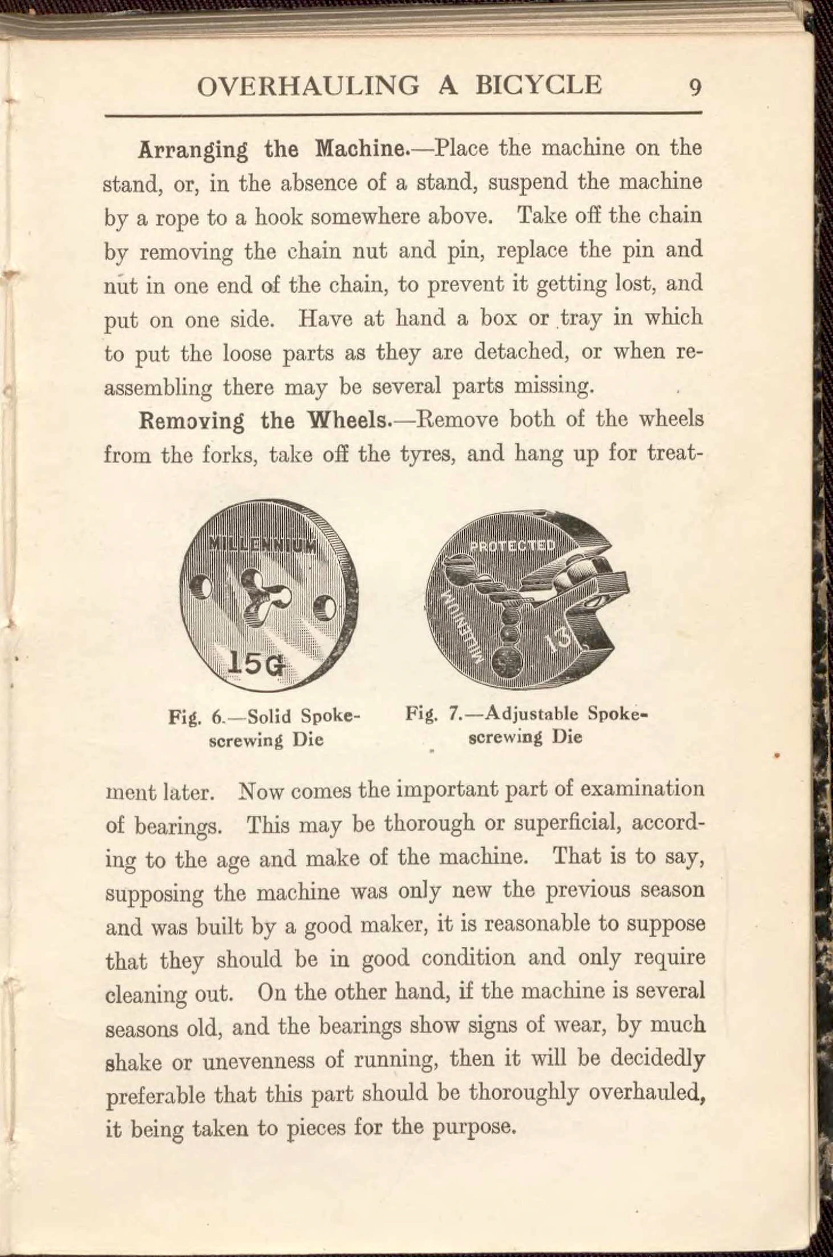
Fig. 6.—Solid Spoke-screwing Die
Fig. 7.—Adjustable Spoke-screwing Die
[Two engraved spoke-screwing dies, a round solid die in Fig. 6 and a round adjustable die with a clamping jaw in Fig. 7, set within the text on overhauling a bicycle. The engravings show the words “Millennium”, “Protected” and the figures 15G and 13 on the dies themselves.]
— Page 22 —
10 CYCLE REPAIRING
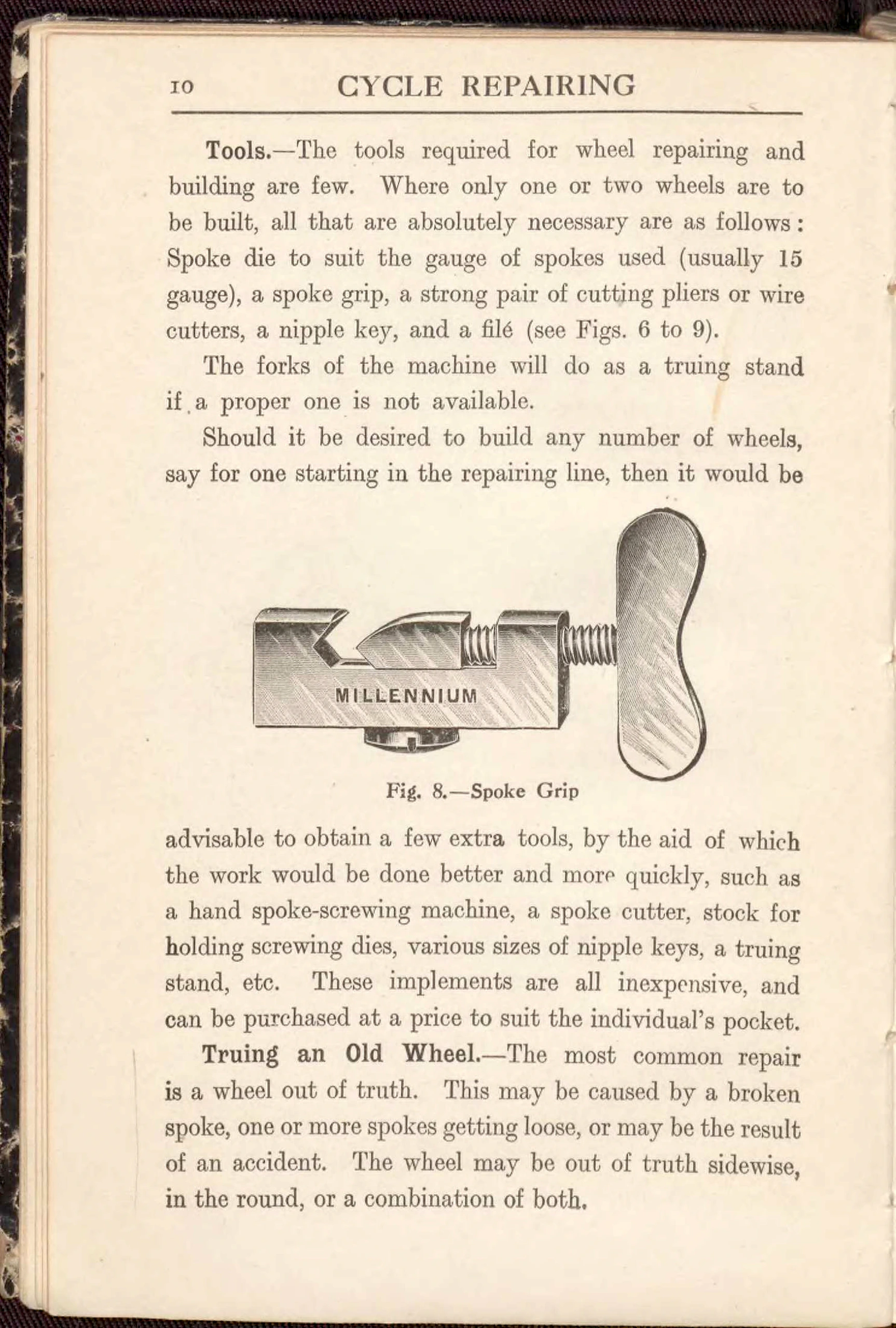
Tools.—The tools required for wheel repairing and building are few. Where only one or two wheels are to be built, all that are absolutely necessary are as follows: Spoke die to suit the gauge of spokes used (usually 15 gauge), a spoke grip, a strong pair of cutting pliers or wire cutters, a nipple key, and a filé (see Figs. 6 to 9).
The forks of the machine will do as a truing stand if a proper one is not available.
Should it be desired to build any number of wheels, say for one starting in the repairing line, then it would be advisable to obtain a few extra tools, by the aid of which the work would be done better and more quickly, such as a hand spoke-screwing machine, a spoke cutter, stock for holding screwing dies, various sizes of nipple keys, a truing stand, etc. These implements are all inexpensive, and can be purchased at a price to suit the individual’s pocket.
Truing an Old Wheel.—The most common repair is a wheel out of truth. This may be caused by a broken spoke, one or more spokes getting loose, or may be the result of an accident. The wheel may be out of truth sidewise, in the round, or a combination of both.
Fig. 8.—Spoke Grip
MILLENNIUM
[An engraved spoke grip, a small screw clamp with a flat thumb screw and the name MILLENNIUM on its body, set within a paragraph on tools for wheel repairing. The paragraph continues below the picture.]
— Page 23 —
OVERHAULING A BICYCLE 11
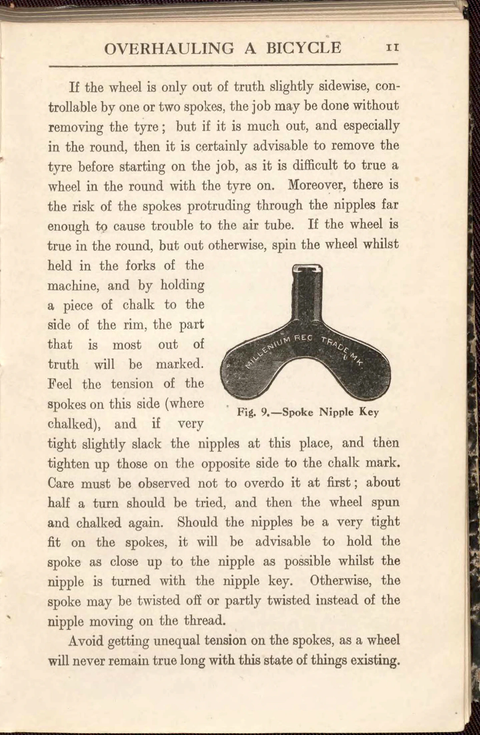
If the wheel is only out of truth slightly sidewise, controllable by one or two spokes, the job may be done without removing the tyre; but if it is much out, and especially in the round, then it is certainly advisable to remove the tyre before starting on the job, as it is difficult to true a wheel in the round with the tyre on. Moreover, there is the risk of the spokes protruding through the nipples far enough to cause trouble to the air tube. If the wheel is true in the round, but out otherwise, spin the wheel whilst held in the forks of the machine, and by holding a piece of chalk to the side of the rim, the part that is most out of truth will be marked. Feel the tension of the spokes on this side (where chalked), and if very tight slightly slack the nipples at this place, and then tighten up those on the opposite side to the chalk mark. Care must be observed not to overdo it at first; about half a turn should be tried, and then the wheel spun and chalked again. Should the nipples be a very tight fit on the spokes, it will be advisable to hold the spoke as close up to the nipple as possible whilst the nipple is turned with the nipple key. Otherwise, the spoke may be twisted off or partly twisted instead of the nipple moving on the thread.
Avoid getting unequal tension on the spokes, as a wheel will never remain true long with this state of things existing.
MILLENIUM REC TRADE MK
Fig. 9.—Spoke Nipple Key
[An engraved illustration of a spoke nipple key, a flat forked tool with a short stem and the words MILLENIUM REC TRADE MK on its body, set in the first paragraph of a page on truing a wheel with chalk and the nipple key.]
— Page 24 —
12 CYCLE REPAIRING
The ideal to be aimed at is to get perfectly equal tension on every spoke in the wheel, then they all do their share, and the wheel will last much longer without further repairs.
Should a wheel be out of truth in the round, fasten a piece of wire across the forks just above the rim as close to it as possible. Then turn the wheel slowly, and observe the low places; these should be chalk-marked, and the spokes let out on both sides at these places. Then find the high places, and tighten up the spokes on both sides at these parts. The exact amount to slacken out and take up in the spokes can only be found out by experience, and will be governed by the tension already on the spokes and the amount the wheel is out of truth; but it is best to be on the safe side, and underdo it rather than overdo it, as a wheel can soon be pulled out of shape and be spoilt by unskilful handling. All the time the truing in the round is going on, a sharp eye must be kept on the condition of the wheel sidewise, and this kept within limits. Frequent trials by spinning the wheel should be made, and want of truth corrected. When the wheel is true in both directions, and all spokes brought to an equal tension, the inside of the rim should be examined, and any spoke ends projecting beyond the surface of the nipple heads filed off so that they cannot penetrate the tube.
One of the secrets of successful wheel building or re-building is getting the nipples a good fit on the spokes. Generally the stock nipples and spokes purchased are too slack to fit, and the vibration gradually loosens the nipples, and thus lets the wheel out of truth. The worker should screw the spokes himself, and get dies that will screw a
[A page of text only, headed with a running head, on truing a wheel in the round and on fitting nipples to spokes. The last sentence is carried over to the next page.]
— Page 25 —
OVERHAULING A BICYCLE 13
tight thread. The job takes longer, but the extra time is well spent.
The correct tension to put on wheel spokes is only found by practice and experience, varying with the gauge of spokes used and the design and make of the rim. A good idea may be obtained by carefully examining a wheel on a new cycle of guaranteed make. It is, of course, possible to overdo it in the matter of tension, and when a wheel is very highly strung, the tendency to go out of truth is often greater than with a moderately tensioned wheel, more especially if the tension on all the spokes is not equal.
Occasionally a wheel that has been recently trued will buckle up without apparent cause. The trouble may be attributed to a weak rim which has previously been buckled, or to unskilful truing up. It will be advisable to fit a new rim, and, when re-building, to take care to get the tension on gradually and equally.
Cycle Out of Track.—If the back wheel is itself true and is fixed truly in the back forks, and the two wheels are then out of track (that is, the rear one does not follow in the track of the front one), either the main frame is bent out of truth or the front fork is bent. See that both wheels are true and truly fixed in their respective forks. Test the front wheel by placing a straightedge against the edge (side) of the rim, and see whether the fork tube is true with this. If it is, then the back frame must be at fault, and must be pulled straight. This may be done cold by placing a long bar down the seat tube and another down the fork tube, using these as levers to pull the frame whichever way is necessary.
[A page of text only, with a running head, on spoke tension, a wheel that buckles after truing and a cycle that is out of track. The first line continues a sentence from the previous page.]
— Page 26 —
14 CYCLE REPAIRING
Fitting a New Rim.—To fit a new rim to replace one broken or so badly dented or knocked about that it would not pay to try and get it true, all the nipples must be unscrewed. A quick way of doing this, if the nipples are slotted on the heads, is with a small brace with a screw-driver bit fixed therein. The nipples can be run off the spokes very quickly by this method. Before beginning to take the wheel to pieces, however, carefully note how the spokes are crossed; that is to say, how many holes apart in the rim each pair of spokes from the flange are. A sketch of the one side may be made, and the spokes and spoke holes numbered to facilitate putting together. It is presumed that the new rim has been purchased ready drilled; this is the best way, as only a few pence extra is charged for drilling.
In putting the wheel together, first bring a pair of spokes up from the flange to the rim the correct number of holes apart, run the nipples on lightly with the fingers, and then find the pair of spokes most directly opposite on the same flange, and bring these up to their proper holes in the rim. This can be ascertained by counting the number of holes in the hub flange between the first pair of spokes and the second on each side, and then counting the holes in the rim. The spoke holes in the rim are not drilled straight, but on the slant; that is, half the holes are drilled to the left and half to the right, looking at the rim from the top. The reason for this is that the nipple and spoke will lie in a straight line from the hole in the hub flange to the hole in the rim when tightened up. It will, therefore, be necessary to look carefully at the rim before putting the first
[A page of text only, with a running head, on fitting a new rim to a wheel and on putting the spokes and nipples together. The last line continues on the next page.]
— Page 27 —
OVERHAULING A BICYCLE 15
pair of spokes in, and note which way each alternate hole is drilled and begin accordingly. With the two pairs of spokes on the one side of the wheel in position, get two pairs on the opposite side similarly fitted. Now screw up the eight nipples equally on the spokes until there is no slack to shake the hub about, but without putting any tension on them. If they have been properly started and screwed up, the wheel should be fairly true when spun round.
With these eight spokes properly spaced, the rest of the putting together is easy; but before going any farther, be sure they are properly spaced by counting the number of vacant holes in the hub flange and rim between each pair of spokes on that side of the rim, and by noting that all eight nipples are screwed on the spokes equally, without there being any tension on them or slackness sufficient to shake the hub and spokes in the rim. Without a perfect start it is impossible to build the wheel properly.
When all the spokes are in position and nipples run loosely on, go round the wheel with the brace or nipple key, and run the rest of the nipples up to very nearly as far on the spokes as those on the first eight. Then get them all up equally, so that there is no shake, and no tension on them.
If all the spokes have been cut dead to one length, the wheel should now be roughly true when spun; but if found much out of truth there will probably be found a spoke or spokes which are too tight at that part, and these must be let out before proceeding farther.
Now begin to get tension on the spokes by screwing
[A page of text only, with a running head, on putting a wheel together, spacing the first eight spokes and bringing the nipples up evenly. The first line continues from the previous page and the last line continues on the next.]
— Page 28 —
16 CYCLE REPAIRING
each one up about half a turn or so, then test, correct if out of truth much, and go round again until the wheel is true, and the spokes have the required and equal tension. File off any protruding spoke ends, and the wheel is finished. The secret of successful wheel-building is: spokes all of one dead length, tension on spokes must be obtained gradually, and equality of spoke tension. If the tension is put on too rapidly at one particular place in the rim, it will be pulled out of shape to such an extent that it will be difficult to get the rim true again in the round.
Fitting New Spoke.—This is a simple job if the wheel has not been made out of truth by the absence of the spoke’s support. Get the length for the new spoke by the old one if still in the rim, or if missing, by one of the others. See that the spoke is of equal gauge and fits the nipple. In the absence of a knowledge of the make of nipples and spoke-screwing with which the wheel is made, it is as well to fit a new nipple, which is known to suit the thread of the new spoke fitted. Tighten up the spoke to an equal tension to the remainder, and test for truth as already explained.
Replacing a broken spoke on the clutch side of a rear wheel without removing the clutch is only a makeshift job, unless the hub flange is provided with slots as well as holes. The job is done by enlarging the hole sufficiently to push the head of the spoke through, or by screwing a small nut or washer on the end after putting through the hole.
Washers used in wheel building are of various patterns, one of the best being that known as the “flanged washer.”
[A page of text only, with a running head, on finishing a wheel build, fitting a new spoke and replacing a broken spoke on the clutch side of a rear wheel. The first line continues from the previous page.]
— Page 29 —
OVERHAULING A BICYCLE 17
This has a turned-up rim round the hole, which minimises the risk of the spoke being pulled through the washer.
Washers for use with wooden rims have turned-down points which dig into the wood.
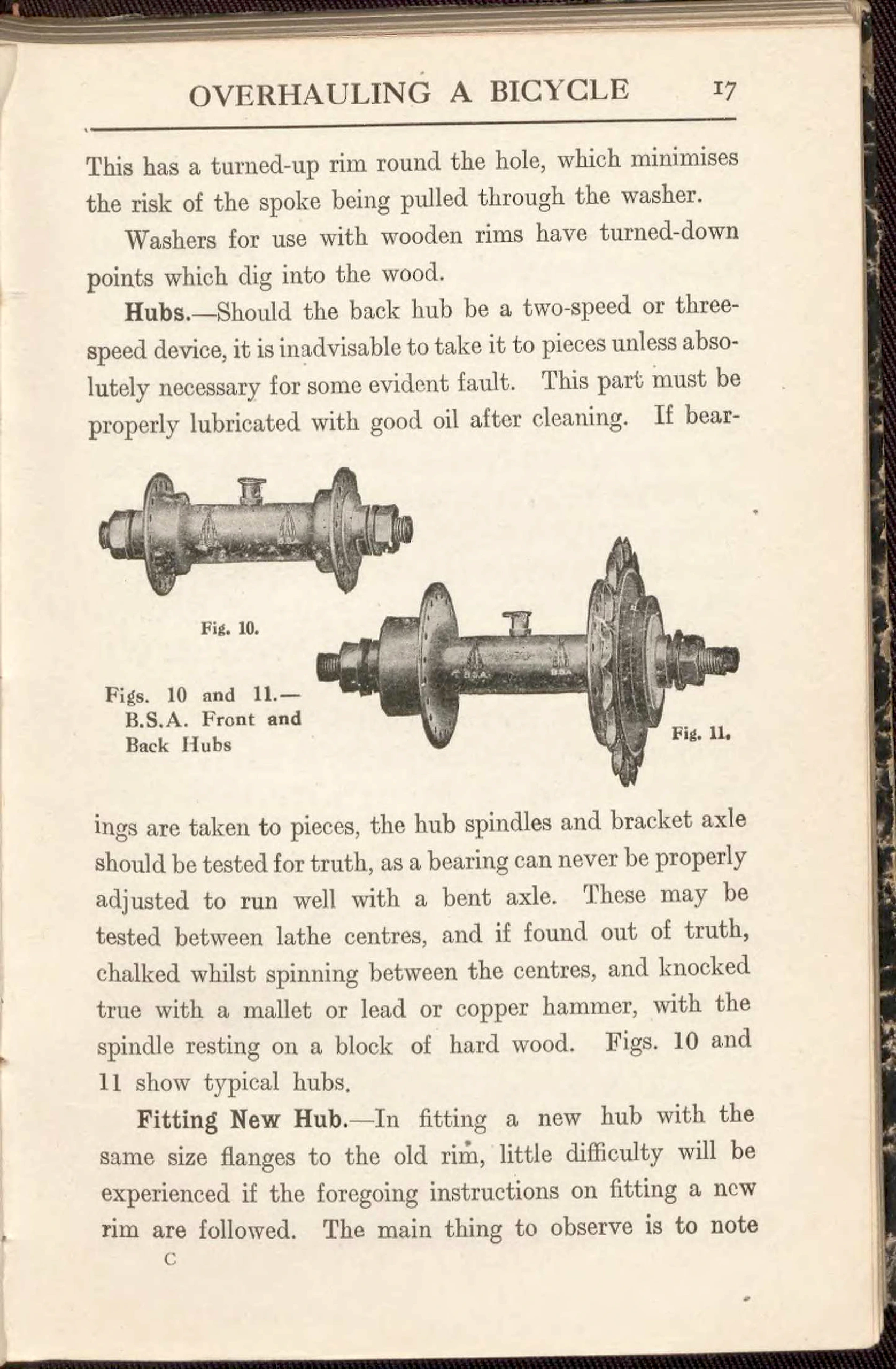
Hubs.—Should the back hub be a two-speed or three-speed device, it is inadvisable to take it to pieces unless absolutely necessary for some evident fault. This part must be properly lubricated with good oil after cleaning. If bearings are taken to pieces, the hub spindles and bracket axle should be tested for truth, as a bearing can never be properly adjusted to run well with a bent axle. These may be tested between lathe centres, and if found out of truth, chalked whilst spinning between the centres, and knocked true with a mallet or lead or copper hammer, with the spindle resting on a block of hard wood. Figs. 10 and 11 show typical hubs.
Fitting New Hub.—In fitting a new hub with the same size flanges to the old rim, little difficulty will be experienced if the foregoing instructions on fitting a new rim are followed. The main thing to observe is to note
Fig. 10.
Figs. 10 and 11.—B.S.A. Front and Back Hubs
Fig. 11.
C
[Two halftone photographs of B.S.A. front and back hubs, the back hub with a toothed sprocket, set between blocks of text on washers, hubs and fitting a new hub. A letter C stands alone at the foot of the page, below the last line of text.]
— Page 30 —
18 CYCLE REPAIRING
carefully how the spokes are crossed in the wheel before taking it to pieces. A very common job is to fit a new two-speed or three-speed or coaster hub in place of an old plain hub. In this case it generally happens that the flanges of the new hub are considerably larger in diameter than the flanges on the old one. This will, of course, necessitate the spokes being so much shorter than before, and the spokes will thus require cutting and re-screwing. The best plan will be to measure the diameter of the old and new hub flanges at the spoke holes, and cut nine spokes shorter by half what this difference may be. For example, assume that the old hub flange at the spoke holes is 1½ in. in diameter and the new ones 2½ in.; cut these nine spokes ½ in. shorter, screw them the required distance, and fit in place as described above; if correct, cut the remainder the same, the odd ninth spoke serving as a gauge for cutting them. The new hub may possibly be drilled a different number of holes from the old one; in this case a new rim will also be required.
Taking down American Bracket Axle.—There will be no particular difficulty in removing one crank and all the cones from the bracket axle of an American cycle, and as much will have then been done as is possible or necessary. The other crank and bracket axle is all one forging, so these cannot be disconnected, but with one crank and all the cones removed the axle should come out of the bracket case.
Removing Sprocket from Coaster Hub.—In taking to pieces a Green and Houk back-pedalling hub, the axle can be taken out and the lock ring removed from the
[A page of text only, with a running head, on fitting a new hub, on taking down an American bracket axle and on removing the sprocket from a coaster hub. The last line continues on the next page.]
— Page 31 —
OVERHAULING A BICYCLE 19
sprocket, but for removing the sprocket a special shaped metal vice clamp, made to fit the part to which the sprocket is screwed, will be desirable. In its absence, the best way will be to replace the hub in the forks of the machine with the brake arm fixed to the chain-stay, and make all tight up in the fork ends. Then place the sprocket remover over the sprocket, put all the pressure on it possible, and if it will not start, give the end of the remover a sharp blow with a hammer whilst pressure is on.
Fitting Free Wheel.—A free wheel clutch can generally be fitted to a hub in the place of a fixed wheel without necessitating any other alteration. The exception is when the clutch is part of a special-pattern hub. To fit a free-wheel, the old chain ring must be removed, and the diameter of the hub barrel and the number of threads to the inch then ascertained, as the free-wheel must agree with the old fixed one in such matters. For removing the old chain ring, it is necessary to take off the lock ring, this having a left-handed screw and unscrewing to the right. The lock nut contains pin-holes, and a pin-spanner fitting in these holes must be used to remove the nut; or it may be knocked round with a hammer and small punch. For removing the chain ring, a punch or a chain-ring remover must be employed. Simply remove the chain, take out the back wheel, remove lock nut and chain wheel, screw the free-wheel on the hub as far as it will go, replace the back wheel and chain, and rotate the crank until the free-wheel is locked tightly against the shoulder of the hub barrel.
Adapting Free-wheel Clutch to a Small Hub.—
[A text page on overhauling a bicycle, with paragraphs on removing a sprocket and on fitting a free wheel clutch, ending with the run-in heading “Adapting Free-wheel Clutch to a Small Hub” and no text after it. There are no illustrations.]
— Page 32 —
20 CYCLE REPAIRING
When a hub is too small and the free-wheel drops in loosely, it can be fixed as follows: Clean the thread well and wind some brass, copper, or tinned iron wire around it, beginning inside after first fastening one end of the wire to a spoke. Wind so that the wire lies in the thread of the screw, and use a wire of sufficient thickness that one layer will make up for deficiency in size. Brush over with soldering fluid and tin well with a copper bit. It will then be seen that the layer of wire is firmly soldered to the hub, and forms by its winding a screw or thread of a diameter greater by twice the thickness of the wire used. Next screw on an old fixed sprocket of the same size and bore as the free-wheel, and when this is removed the free-wheel can be screwed on quite easily. This does not appear to be exactly a workshop method, but its reliability has been proved.
Free-wheel Clutch Slipping.—If a clutch slips when forward pedalling, it cannot be remedied by outside adjustment; it must be taken to pleces, and the cause of slipping ascertained. The fault may be one of the following: A worn-out clutch, oil being clogged and thus rendering the light springs used in free wheels inoperative, or the springs themselves may be weak. The remedy is: Before taking the cycle to pieces squirt some petrol or paraffin through the free-wheel; with the machine on its side, revolve the wheel rapidly, and let all the liquid drain out, then lubricate with good oil. If this does not effect a cure, take the clutch to pieces and see what is wrong, and send to the makers for any new parts required. Gummed-up oil and wear are frequent causes of trouble.
[A text page on overhauling a bicycle, with paragraphs on adapting a free-wheel to a small hub with wire and on a slipping free-wheel clutch. There are no illustrations.]
— Page 33 —
OVERHAULING A BICYCLE 21
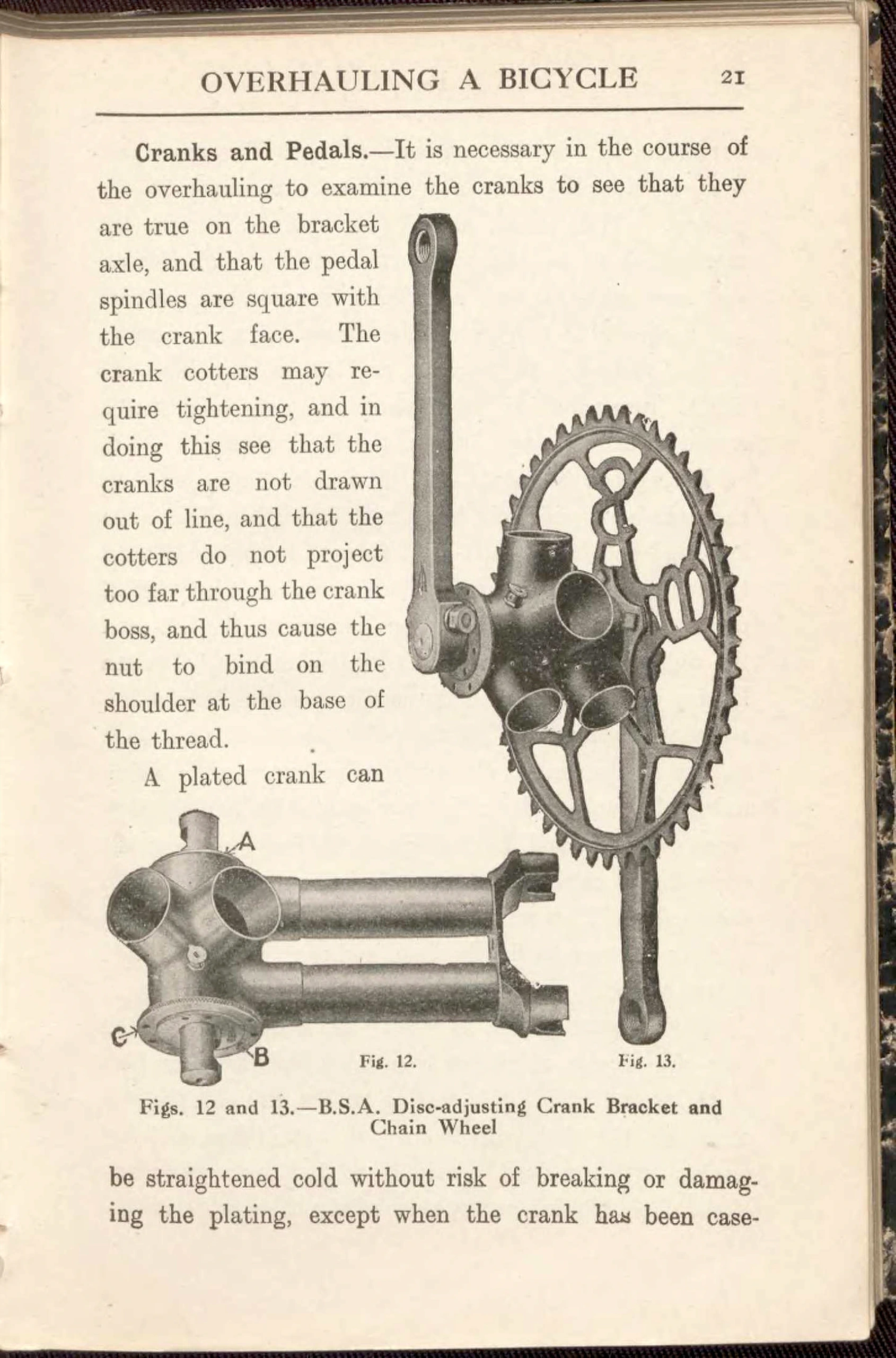
Cranks and Pedals.—It is necessary in the course of the overhauling to examine the cranks to see that they are true on the bracket axle, and that the pedal spindles are square with the crank face. The crank cotters may require tightening, and in doing this see that the cranks are not drawn out of line, and that the cotters do not project too far through the crank boss, and thus cause the nut to bind on the shoulder at the base of the thread.
A plated crank can be straightened cold without risk of breaking or damaging the plating, except when the crank has been case-
Callouts: A B C
Fig. 12.
Fig. 13.
Figs. 12 and 13.—B.S.A. Disc-adjusting Crank Bracket and Chain Wheel
[The B.S.A. Disc-adjusting Crank Bracket and Chain Wheel in two halftone photographs, Figs. 12 and 13, with the text on cranks and pedals set beside them. Fig. 12 shows the bracket with the letters A, B and C printed on it with arrows; Fig. 13 shows a crank, bracket shell and chain wheel.]
— Page 34 —
22 CYCLE REPAIRING
hardened. It is then as well to heat the bent part with a blowpipe, but not sufficient to discolour the plating. The crank should be removed from the machine, held in the vice jaws between lead clamps, and bent straight with a twisting wrench, the jaws of which should be lined with sheet brass to avoid damage to the plating. In Figs. 12 and 13, which show the B.S.A. disc-adjusting crank bracket and chain wheel, A and B indicate cups, and C the locking ring.
Fixing Loose Pedals.—In all machines of recent make the right-hand pedal pin has a right-hand thread, and the left-hand pedal pin a left-hand thread, so that both tend to tighten up when riding. Still, there are hundreds of machines in use with old-pattern pins, both the left- and the right-side pins having right-handed threads. Various locking devices were formerly used to prevent the pins unscrewing when riding. If the pedal pin thread is a slack fit, the left pin in an old machine will unscrew in riding unless the locking device is very good. To remedy this, remove the pin, and, having heated the crank end and the screw thread until too hot to touch, well smear with Prout’s elastic glue. Then screw tight while hot, and lock securely. The pin will now be tightly fixed, and cannot be unscrewed unless heated.
Hard Running Due to “Set” of Machine.—In the case of a bicycle which has been made up with a bracket of 1⅝ in. and 1¾ in. hub, testing with a straightedge will show that the chain wheels are ⅛ in. out of line, and the machine will run hard, especially at first, in consequence of the chain binding on the sides of the chain-wheel teeth.
[A text page on overhauling a bicycle, with paragraphs on straightening a plated crank, fixing loose pedals and hard running due to the set of a machine. There are no illustrations.]
— Page 35 —
OVERHAULING A BICYCLE 23
If the conditions were reversed—that is to say, a 1¾-in. bracket and a 1⅝-in. hub chain line—it would not be so bad, as it is the practice of some makers to set the machine so that a straightedge held against the outside face of the bracket wheel will be 1/16 in. “off” the face of the hub wheel; the theory being that when pressure is applied to the pedals, the small amount of spring in the back part of the frame will bring the chain line correct when riding. If the back forks are set so that the chain wheels are in line, the difference will not matter a great deal.
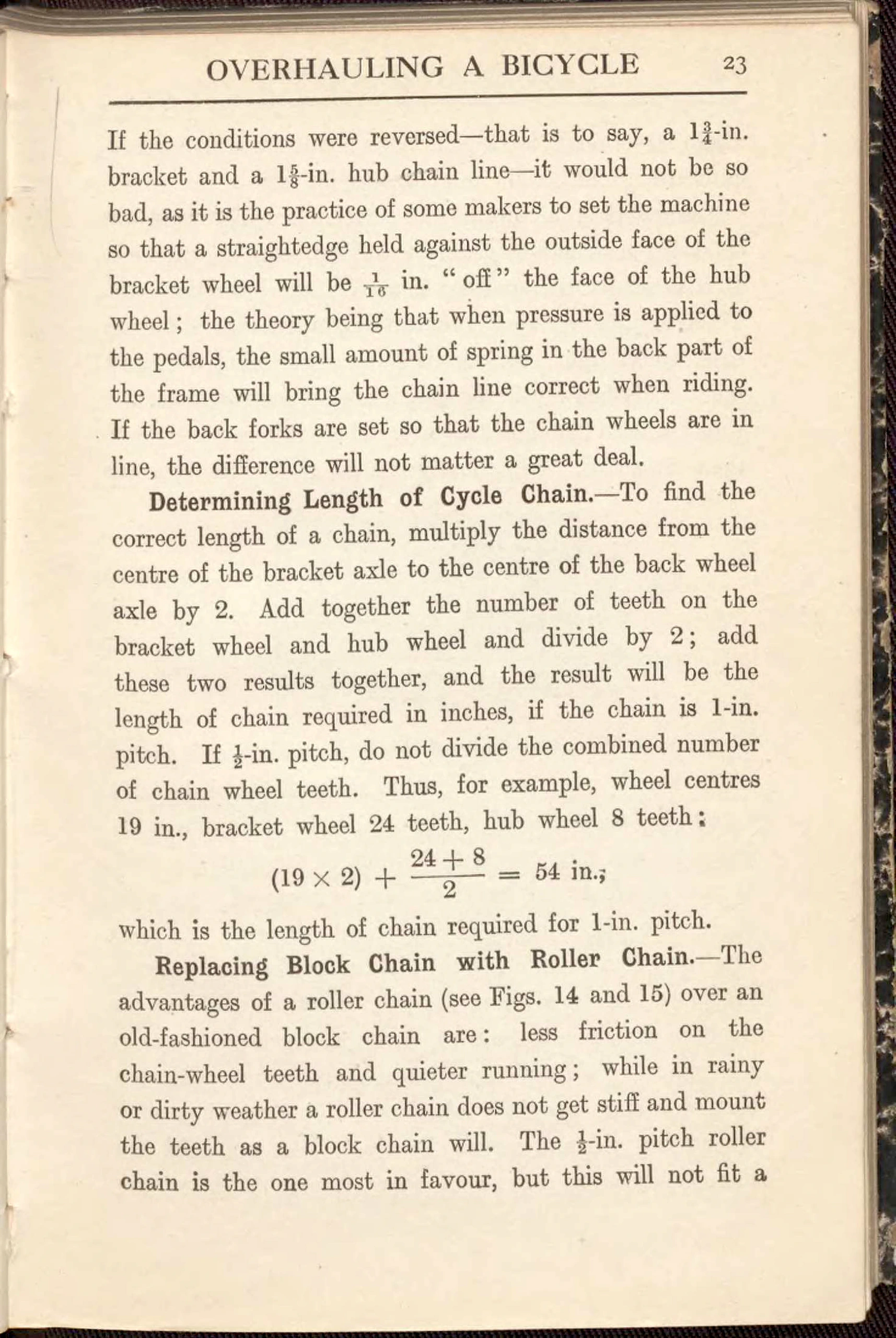
Determining Length of Cycle Chain.—To find the correct length of a chain, multiply the distance from the centre of the bracket axle to the centre of the back wheel axle by 2. Add together the number of teeth on the bracket wheel and hub wheel and divide by 2; add these two results together, and the result will be the length of chain required in inches, if the chain is 1-in. pitch. If ½-in. pitch, do not divide the combined number of chain wheel teeth. Thus, for example, wheel centres 19 in., bracket wheel 24 teeth, hub wheel 8 teeth:
(19 x 2) + (24 + 8)/2 = 54 in.;
which is the length of chain required for 1-in. pitch.
Replacing Block Chain with Roller Chain.—The advantages of a roller chain (see Figs. 14 and 15) over an old-fashioned block chain are: less friction on the chain-wheel teeth and quieter running; while in rainy or dirty weather a roller chain does not get stiff and mount the teeth as a block chain will. The ½-in. pitch roller chain is the one most in favour, but this will not fit a
[A text page on overhauling a bicycle, with paragraphs on chain line, determining the length of a cycle chain with a worked sum, and replacing a block chain with a roller chain. The sum is set with a stacked fraction, 24 + 8 over 2; there are no illustrations.]
— Page 36 —
24 CYCLE REPAIRING
chain wheel made for a 1-in. block chain, for which a 1-in. pitch twin-roller chain will have to be used.
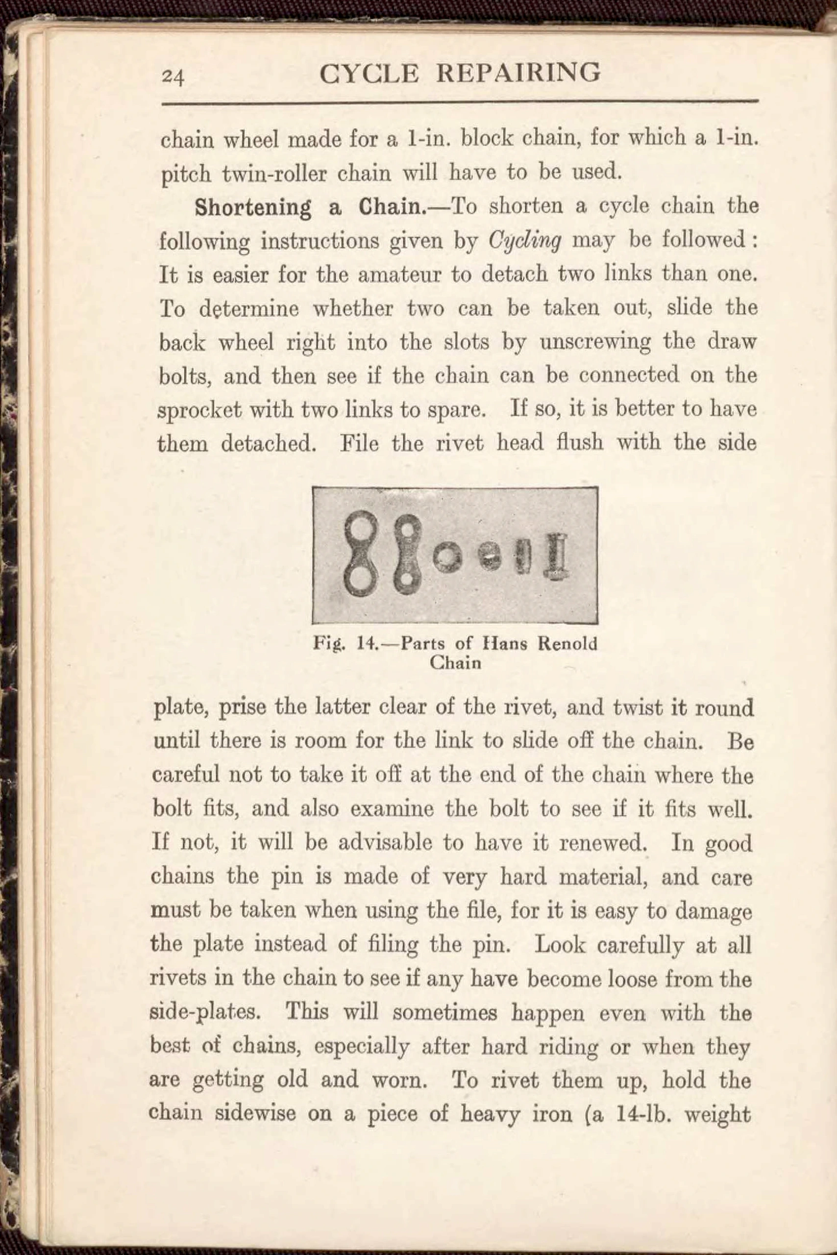
Shortening a Chain.—To shorten a cycle chain the following instructions given by Cycling may be followed: It is easier for the amateur to detach two links than one. To determine whether two can be taken out, slide the back wheel right into the slots by unscrewing the draw bolts, and then see if the chain can be connected on the sprocket with two links to spare. If so, it is better to have them detached. File the rivet head flush with the side plate, prise the latter clear of the rivet, and twist it round until there is room for the link to slide off the chain. Be careful not to take it off at the end of the chain where the bolt fits, and also examine the bolt to see if it fits well. If not, it will be advisable to have it renewed. In good chains the pin is made of very hard material, and care must be taken when using the file, for it is easy to damage the plate instead of filing the pin. Look carefully at all rivets in the chain to see if any have become loose from the side-plates. This will sometimes happen even with the best of chains, especially after hard riding or when they are getting old and worn. To rivet them up, hold the chain sidewise on a piece of heavy iron (a 14-lb. weight
Fig. 14.—Parts of Hans Renold Chain
[A halftone photograph of the parts of a Hans Renold Chain, Fig. 14, six small pieces laid out in a row in a framed picture, set between two parts of one paragraph on shortening a chain. The text of the page ends in mid sentence.]
— Page 37 —
OVERHAULING A BICYCLE 25
will do), and rivet over the heads by hammering until they fit tightly in the side-plates.
Chain Bolt.—Accidents sometimes occur through the chain bolt becoming disengaged from the chain. The bolt nut should periodically be examined, and tightened if necessary. All nuts and bolts require occasional overhauling. It does not take many minutes to run a spanner over all the nuts on the machine, and the time will be well spent. The employment of a poor spanner bruises the nuts and spoils the appearance of a machine.
Fig. 15.—Hans Renold Chain
Cleaning Chains.—To clean a chain thoroughly it is necessary to remove it from the machine. The chain bolt and nut should be placed in a receptacle where they cannot be easily mislaid. The chain should then be coiled and soaked for about twenty-four hours in a shallow dish or tray containing paraffin; when the chain is removed, hang it over the dish to drain. To lubricate the chain, it may be placed in a dish containing melted russian tallow, or treated externally with graphite. The former will be found more thorough, as the melted tallow finds its way into every link and rivet. A chain treated thus will not require any further lubrication for a considerable time.
[A line drawing of the Hans Renold Chain in section, Fig. 15, with four arrows pointing to parts of it, set between paragraphs on the chain bolt and on cleaning chains. The arrows carry no letters.]
— Page 38 —
26 CYCLE REPAIRING
The best method is to melt some russian tallow in a shallow tin dish, just sufficient to cover the chain, which may be coiled. Stand the tin on a stove or in a warm oven for an hour or so. Then hang up the chain to drain off superfluous tallow whilst warm, and wipe the chain with a cloth. This will thoroughly lubricate the chain in every link and rivet, and will last for a considerable time. The outside of the chain may be brushed over with graphite or blacklead, if the machine is not fitted with a metal gear-case. Should an oil-bath gear-case be fitted, the old oil should be emptied out, the gear-case cleaned out with paraffin, and fresh oil put in.
Instead of the russian tallow, mutton suet, cut up fine, may be used. The chain, having been cleaned in paraffin as before, is placed in an old tin and covered with about ½ lb. of the cut-up suet. Then place the tin in an oven sufficiently hot to melt the suet. Let the chain lie in this for three or four hours, then wipe carefully and replace it on the machine, finally giving the chain a dusting of graphite well brushed in.
Making Stick Lubricant.—A suitable lubricant for cycle chains is blacklead and tallow. Melt the latter (russian tallow for preference), and thoroughly stir in the powdered graphite until the mixture is of the desired consistency, when it should be poured into moulds to set. Pieces of steel cycle tube, cut to the desired length, may be used as moulds; the mixture should afterwards be pushed out, when set, with a stick the size of the inside diameter of the tube. This, whilst making an excellent lubricant for the outside of the chain, is not of much use
[A text page on overhauling a bicycle, with paragraphs on lubricating a chain with tallow or suet and on making stick lubricant. There are no illustrations.]
— Page 39 —
OVERHAULING A BICYCLE 27
for the interior, unless the chain is immersed in the mixture whilst this is hot and liquid, when it will find its way into all parts, and form one of the very best chain lubricants obtainable.
A good lubricant for external application to chains consists of plumbago and vaseline. Any good make of blacklead will do, but specially prepared plumbago is better. Crush the blacklead to a fine powder and mix thoroughly with twice the bulk of good vaseline and a little lubricating oil.
Adjusting Wheels and Chain.—When adjusting the wheels and bracket, do so before replacing the chain, and the best way is to tighten up the cone rather too tight, and then slack back a trifle until the wheel or bracket will oscillate without any perceptible side shake. When adjusting the chain, see that the back wheel is quite true in the forks both at the bottom and top, and have the chain so adjusted that there is a slight sag at both the top and bottom.
Examining and Cleaning Bearings.—For cleaning bearings without going to the trouble of taking them to pieces, proceed thus: Fill an oil-can having a fine point with paraffin, and thoroughly swill out the bearings by squirting the paraffin through the lubricators, and revolving the bearings repeatedly until the paraffin runs out quite clean. Place the wheels and frame on its side, so that all paraffin may drain out. Then if there is any shake or play in the bearings, take this up, and spin the wheel or bracket, whichever it may be, and listen carefully if there is any “click” to be heard when the bearing is revolved.
[A text page on overhauling a bicycle, with paragraphs on lubricating chains with blacklead and vaseline, adjusting wheels and chain, and examining and cleaning bearings. There are no illustrations.]
— Page 40 —
28 CYCLE REPAIRING
If so, it is certain that there is a broken or chipped ball, or a bad place in the cone or cup, and that particular bearing should be taken out for examination. The parts must be wiped quite clean, and every ball carefully examined, as well as the cones and cups. If a chipped, rough, or broken ball is revealed, replace it with a new one, being sure it is of the same diameter. If a bad or unevenly worn cone, cup, or bracket disc is the fault, obtain a new one and replace.
When spinning the bearing to detect any fault, after it has been cleaned out, a noise may be heard of the balls dropping on one another as they revolve. This is as it should be, and must not be confounded with a ” click ” caused by a defective bearing.
After cleaning out, all bearings must be lubricated with some good oil. Pure sperm is as good as anything, and much better than some of the oils put up in tins with a fancy name. Many of these are composed of the greater part paraffin, which is no good whatever as a lubricant.
It is a good plan to alter the position of the bottom-bracket discs by turning the fixed or chain-wheel side half a revolution in the bracket. This will bring a fresh portion of the disc into position to receive the greatest amount of wear. This also applies to wheel spindles and the bottom-head cone or race of the fork crown. The position of the pedal spindles might also be moved in the crank ends by fitting a very thin washer behind the pedal pin shoulder.
The bearings should be thoroughly cleaned out and properly adjusted, so that they run free, but without shake. The best way to do this is to tighten them
[A page of continuous text on cleaning, examining and lubricating cycle bearings, with no illustrations. The scan shows a dark mottled edge along the left side.]
— Page 41 —
OVERHAULING A BICYCLE 29
home, and then slack the cone back for a quarter or a half revolution. See that all lock nuts are securely tightened up.
Before cleaning out the bearings of a fully-equipped bicycle, tie rags round any part where the oil is likely to run out, as otherwise the tyres will be messed up. Mineral oil is not good for rubber.
Cleaning Free-wheel Clutch.—The clutch should be cleaned by running some petrol or benzoline through it until it runs out fairly clean ; then let the petrol drain out, and lubricate with good oil. The machine should be leaned over to one side while the clutch is being cleaned, to prevent the tyres getting damaged. If the clutch runs very stiff after being cleaned and oiled, it has probably been badly fitted on the hub. If the clutch is a ” rachet ” type, it will always make a certain amount of noise compared with a ” friction ” type. It is not necessary to take the clutch to pieces to clean it. If petrol is not handy, use ordinary paraffin oil.
Cleaning and Lubricating New Departure Hub.—Fill an oil can with petrol, lean the cycle over to one side to keep the tyres free from the spirit and oil, and squirt the spirit through all oil holes, turning the wheel frequently and rapidly until the spirit runs out fairly clean ; then lean the cycle over to the other side, and repeat the process. When all the spirit has drained out, well lubricate the hub with good oil, such as sperm oil. For the brake surfaces, a heavier oil, such as motor cylinder oil, is advisable, as the heat created by the friction of the brake soon dries up a thin body oil. Many riders think that the brake
[A page of continuous text under the running head Overhauling a Bicycle, with run-in headings on cleaning a free-wheel clutch and on cleaning and lubricating a New Departure hub, and no illustrations. The scan shows a dark mottled edge along the right side.]
— Page 42 —
30 CYCLE REPAIRING
surfaces should not be oiled ; but, as a matter of fact, this part requires frequent lubricating. Were ordinary oil used for the purpose, it would run out of the hub, owing to the heating of the brake. To overcome this difficulty a proper lubricant must be used. This is the motor cylinder oil mentioned above, or a non-fluid oil melting at 356° F., made expressly for lubricating these hubs ; it can be bought of most cycle dealers. To lubricate, take down the hub, remove the brake clutch from the brake, and pack the interior of the brake with lubricant, applying a little to all bearings of the hub. Then fit together again, and if this is properly done, the hub will not give trouble for twelve months’ ordinary running. Mr. J. Veitch Wilson, the well-known authority on lubricants, dislikes both sperm oil and stauffer grease for coaster hubs, and recommends some such lubricant as Price’s ” cycle axle oil ‘ B.’ ”
Keeping Dust from Cups of Bottom Brackets.—Cycling recommends the following method, which renders the cups almost oil-retaining in their character : Take a piece of velveteen, and cut a hole in it sufficiently large to pass over the axle, with an outside diameter equal to that of the cup. If one or more pieces are placed on the axle before the cranks are cottered up, the surplus oil will be retained by this washer, and at the same time dust cannot get in. If the pieces are too thick, possibly a slight amount of friction may be caused, but it will speedily disappear with wear.
The Frame.—A thorough examination of the frame should be made, especially at the joints where tubes are brazed into the lugs, for broken joints, cracked tubes, etc.
[A page of continuous text on lubricating a coaster hub, keeping dust from bottom bracket cups and examining the frame, with no illustrations. The scan shows a dark mottled edge along the left side.]
— Page 43 —
OVERHAULING A BICYCLE 31
The fork crown is a very vital part, and to examine this it should be removed from the head of the machine, and examined where the steering tube enters the fork crown.
When a cycle has a tendency to run to one side, the defect is probably due to a fall, which has had the effect of putting the frame or fork out of truth. In order to test this and correct it, see that the front wheel is true between the forks at the rim. Then with a straightedge placed against the side of the rim, test each side with the handle-bar stem. The straightedge should be at the same distance from the handle-bar stem on each side. Unless the tyres are quite true, they should be removed before trying this. If the fork is found to be out of truth, it must be removed from the head, the wheel removed, and the forks pulled over in the vice one at a time. When correct, replace and, with the machine upside down, place a long straightedge against each side of the back rim, noting whether it falls equidistant at both sides of the front rim. If this is correct, turn the machine right side up, and try the straightedge from the rear wheel rim sides to a piece of ⅞-in. tube placed in the fork tube. If these are correct, the machine should ” track ” or run true. If ” out,” the frame must be pulled over or twisted accordingly. The front fork should also be tested to see that the blades are parallel with each other. To test this, place a piece of straight tube or rod through the spindle holes and a straightedge across the blades near the crown ; they should be parallel with each other. Finally, see that the handle-bar[?] is set quite square with the front wheel.
[A page of continuous text on testing the fork crown, the fork blades and the alignment of the frame, with no illustrations. The scan shows a dark mottled edge along the right side.]
— Page 44 —
32 CYCLE REPAIRING
Cleaning the Frame.—Frequently the frame enamel is spoilt owing to careless cleaning. If mud has hardened on it, sponge this off before polishing with a soft cloth. The use of a dry cloth or stiff brush on the mud usually removes a little of the enamel.
Repairing Front Fork.—To repair a front fork that has been bent sideways in a collision, remove the wheel and fork from the machine, heat one blade at a time, and bend it back into its proper place. Hold the fork by the steering tube in the vice and pull the blade by hand. Treat the other blade in the same way, and see that the fork ends are at the correct distance apart to suit the hub. The blade should be heated with a gas blowpipe ; no very great heat is necessary, just a suspicion of redness at the worst part of the bend being wanted. Place a straight piece of rod through the spindle holes, and another piece across the blades just below the crown. These two pieces of rod, when looked at from the top of the steering tube, should be parallel. Now replace the wheel in the fork, with the rim quite central therein, and with a straightedge on the sides of the rim test the steering tube for being central.
Ball Head Clicking.—The usual cause of the ball head of a bicycle clicking when riding is that the bottom ball-race has become indented by the balls, caused by the road shocks ; or one or more of the balls may be dented or chipped ; or the steering or fork tube may be cracked, and the click caused by the edges of the crack rubbing together. Well clean the bearing races, balls, and tube, and then thoroughly inspect. If the clicking is not due
[A page of continuous text under the running head Cycle Repairing, with run-in headings Cleaning the Frame, Repairing Front Fork and Ball Head Clicking, and no illustrations. A fine gray hairline runs down the left margin beside the second paragraph.]
— Page 45 —
OVERHAULING A BICYCLE 33
to one of the above causes, look elsewhere for the defect —for instance, to the front hub bearings.
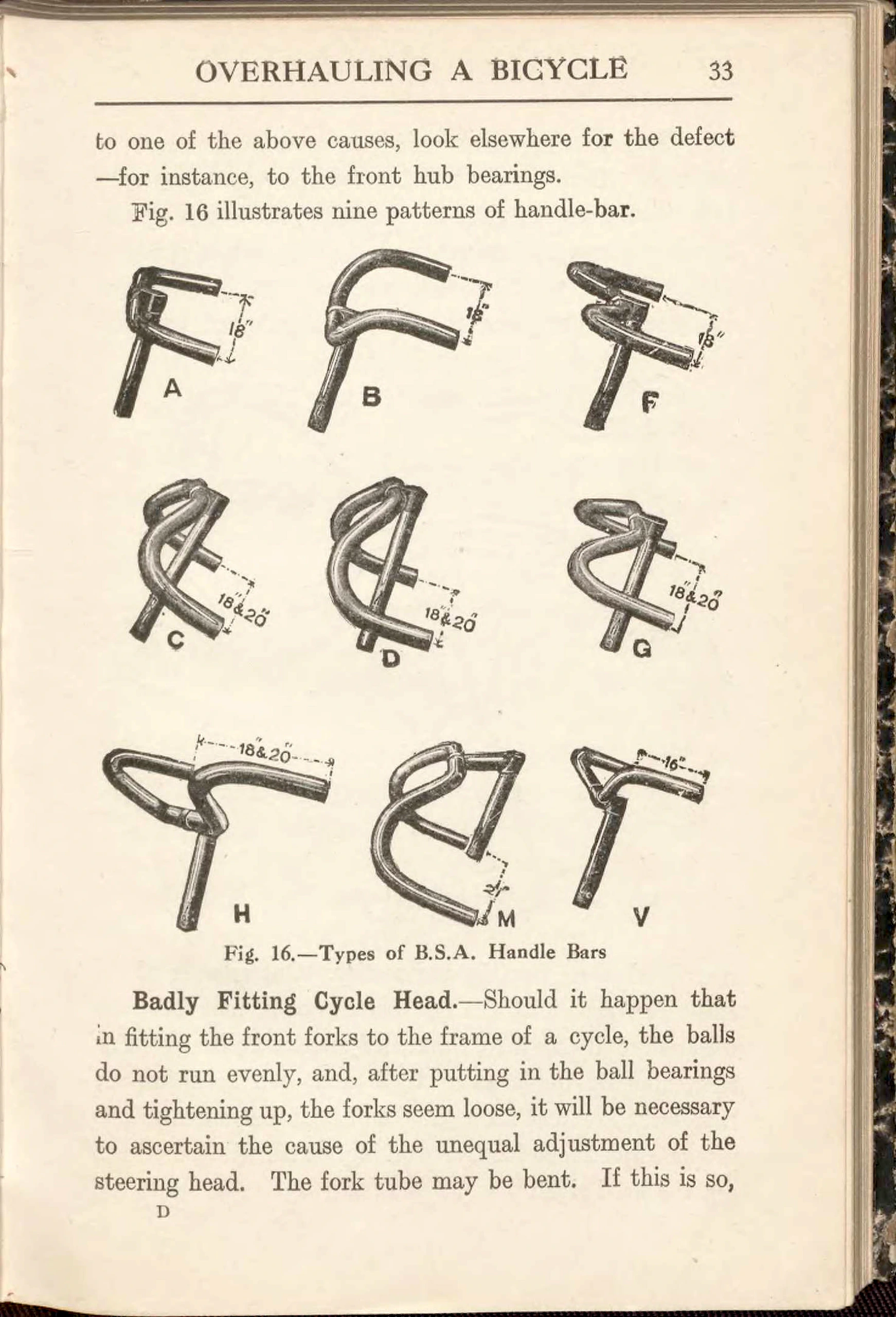
Fig. 16 illustrates nine patterns of handle-bar.
Callouts: A 18″ B 18″ F 18″ C 18″&20″ D 18″&20″ G 18″&20″ H 18″&20″ M 2[illegible]” V 16″
Fig. 16.—Types of B.S.A. Handle Bars
Badly Fitting Cycle Head.—Should it happen that in fitting the front forks to the frame of a cycle, the balls do not run evenly, and, after putting in the ball bearings and tightening up, the forks seem loose, it will be necessary to ascertain the cause of the unequal adjustment of the steering head. The fork tube may be bent. If this is so,
D
[Nine B.S.A. handle bar patterns lettered A, B, F, C, D, G, H, M and V in a three by three grid of engraved drawings, each with a dashed dimension line marked in inches. A printer’s signature letter D stands at the foot of the page, and the scan shows a dark mottled edge along the right side.]
— Page 46 —
34 CYCLE REPAIRING
it can be set true by hammering on wood blocks cut to fit the tube. Three blocks will be required, two to rest the tube on and one to place on the bent part to receive the hammer blows. After hammering, test with a straightedge. One of the head ball-races may be fitted out of truth, or the ball-race on the crown may not be truly
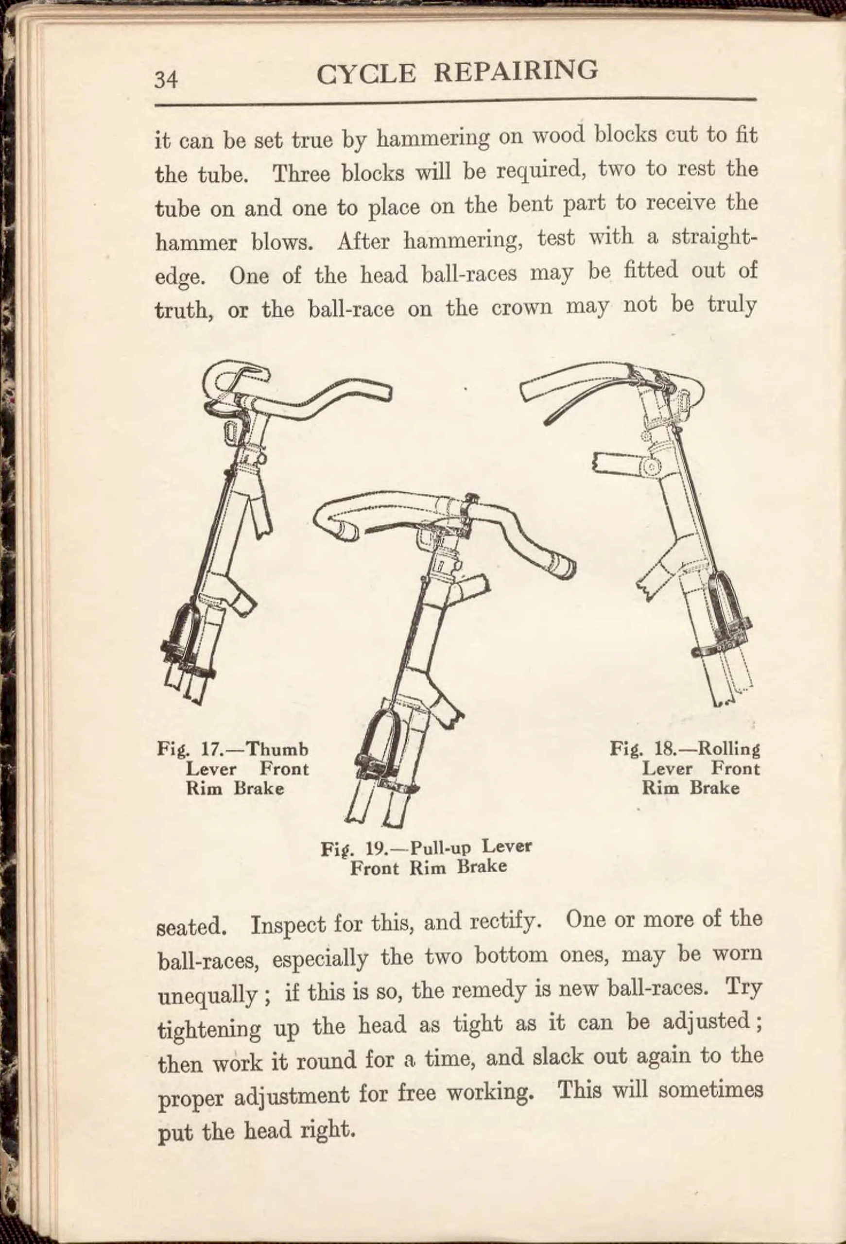
Fig. 17.—Thumb Lever Front Rim Brake
Fig. 18.—Rolling Lever Front Rim Brake
Fig. 19.—Pull-up Lever Front Rim Brake
seated. Inspect for this, and rectify. One or more of the ball-races, especially the two bottom ones, may be worn unequally ; if this is so, the remedy is new ball-races. Try tightening up the head as tight as it can be adjusted ; then work it round for a time, and slack out again to the proper adjustment for free working. This will sometimes put the head right.
[Three line drawings of handlebars with stems and front forks fitted with a thumb lever, a rolling lever and a pull-up lever front rim brake, set between two blocks of text. The scan shows a dark mottled edge along the left side.]
— Page 47 —
OVERHAULING A BICYCLE 35
Handles.—The handle grips should be examined, and, if found loose, removed and refixed. To refix, warm the handle-bar end in the gas, and melt a little solid-tyre cement into the grip and push home. Care must be taken not to get the handle-bar end too hot, especially if the grips are of celluloid or fitted with celluloid tips or ferrules, or they will be spoilt. Any superfluous cement which may show on the handle-bar may be wiped off whilst still hot with a paraffin rag.
Another method of refastening handles is as follows : After removing the grips, a small quantity of glue should be poured inside them, and the grips turned about until the inner surface is covered with the glue. Then tip them upside down to remove the superfluous glue, and place them on the handle-bars. They must not be used until the glue has had sufficient time to set, or the grips will work loose again.
Brakes.—Brakes should be examined for loose and worn parts, and adjusted and renewed where required. Probably new brake blocks may with advantage be fitted.
Three of the many patterns of B.S.A. brakes are shown in Figs. 17 to 19.
Mudguards.—A celluloid front mudguard may easily be broken by the foot catching in it when turning a corner quickly. It can be repaired by riveting a piece of tinplate 6 in. long by about 2½ in. wide to the under-side of the guard. Holes should then be punched in the guard and the plate to receive the rivets ; usually about ten holes will be sufficient. The tinplate should be enamelled to
[A page of continuous text under the running head Overhauling a Bicycle, with run-in headings on handles, brakes and mudguards, and no illustrations. Small brownish notches mark the left paper edge, and a dark mottled edge runs along the right side.]
— Page 48 —
36 CYCLE REPAIRING
prevent it from rusting. Suitable copper rivets can be obtained from any ironmonger.
The following hints on mudguards are due to Cycling : When ordering guards, state whether they are for 26-in. or 28-in. wheels ; there is no difference in the size of the guard, but there is in the length of stays. A noisy guard can be cured by leather washers, or by winding string round the stay before bolting down the guard. If the guard does not lie close enough to the wheel, bend the end of the stay to a right angle, and fit it so ; this is neater than twisting it into a zig-zag. A front wheel guard that stands too far out may bring the rider over at a corner by coming into contact with his toe. Much of the mud that accumulates on the chain wheel may be stopped by the use of a flap on the end of the front guard. A triangle of enamelled tin, fitted in the corner between the rear guard and the chain stay, on the chain side, will save the chain a lot of wear and trouble. Thorn-catchers should be fitted to the lower, not to the upper, stay of a mudguard ; any mud scraped off by them will then fall on to the road instead of on to the hub of the wheel. Special side mud-splashers can be bought for fitting to the chain stays and sides of front wheel. Forward extensions to the front mudguard desirable in the winter are easily fitted.
Rust.—If rust has not formed too thickly on the nickel plating, it may often be removed by rubbing the affected parts with a rag dipped in sweet oil. Should this fail, rub with a piece of emery-cloth. The parts will then require enamelling or replating, otherwise rust will quickly form again.
[A page of continuous text under the running head Cycle Repairing, on mudguard hints and on removing rust from nickel plating, with a run-in heading Rust and no illustrations. The scan shows a dark mottled edge along the left side.]
— Page 49 —
OVERHAULING A BICYCLE 37
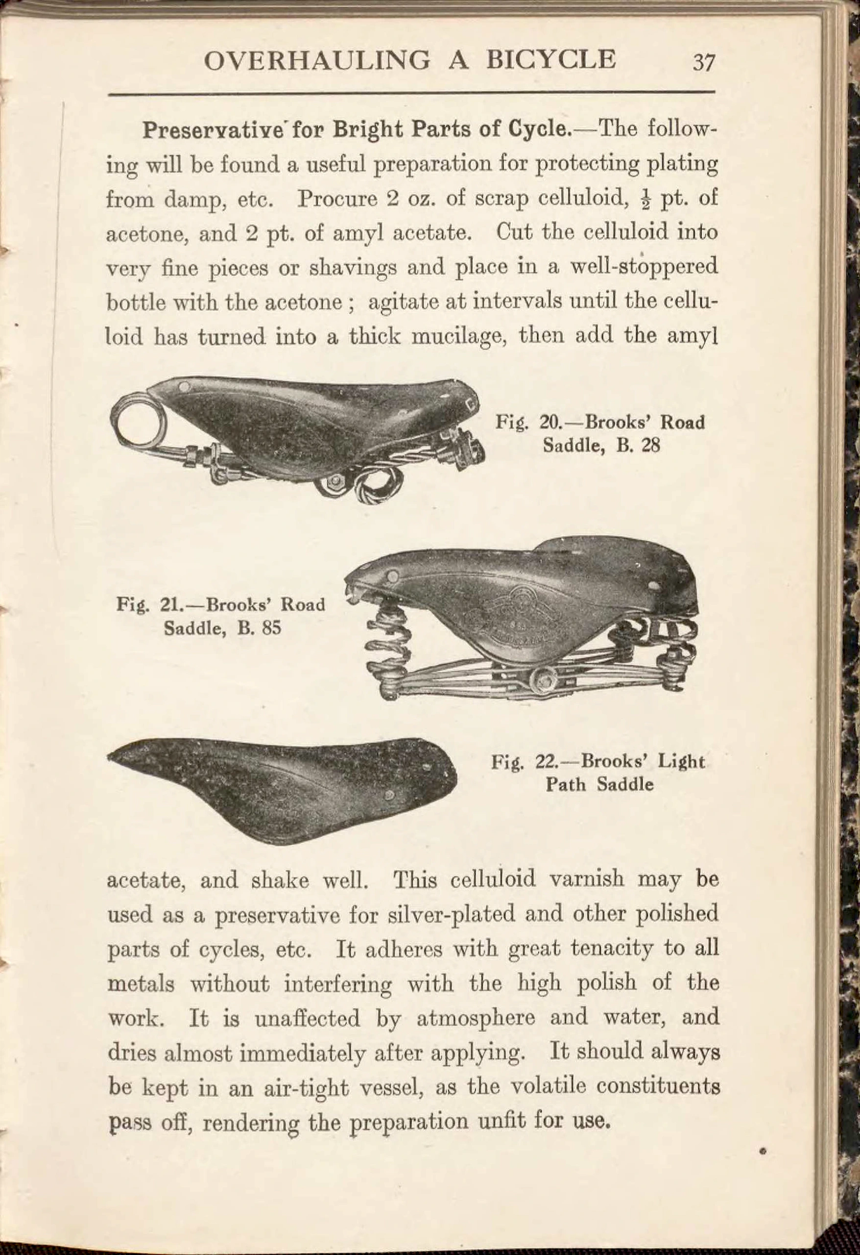
Preservative for Bright Parts of Cycle.—The following will be found a useful preparation for protecting plating from damp, etc. Procure 2 oz. of scrap celluloid, ½ pt. of acetone, and 2 pt. of amyl acetate. Cut the celluloid into very fine pieces or shavings and place in a well-stoppered bottle with the acetone ; agitate at intervals until the celluloid has turned into a thick mucilage, then add the amyl acetate, and shake well. This celluloid varnish may be used as a preservative for silver-plated and other polished parts of cycles, etc. It adheres with great tenacity to all metals without interfering with the high polish of the work. It is unaffected by atmosphere and water, and dries almost immediately after applying. It should always be kept in an air-tight vessel, as the volatile constituents pass off, rendering the preparation unfit for use.
Fig. 20.—Brooks’ Road Saddle, B. 28
Fig. 21.—Brooks’ Road Saddle, B. 85
Fig. 22.—Brooks’ Light Path Saddle
[Three photographs of Brooks leather saddles: the Road Saddle B. 28, the Road Saddle B. 85 and the Light Path Saddle, set in the middle of a paragraph on a preservative for bright parts of a cycle. The first two saddles are shown from the side with their springs; the third shows the leather top only.]
— Page 50 —
38 CYCLE REPAIRING
The celluloid varnish forms the best medium for mixing with metallic bronzes to make aluminium paint, gold paint, etc., with which certain parts of machines can be protected. Procure some finely divided aluminium bronze powder and mix sufficient of this with the medium for immediate use.
It has been remarked that taking care of a bicycle is chiefly a matter of keeping it clean. After a ride, the machine should be cleaned, the dust and dirt removed, the surplus oil wiped off, and the tyres carefully examined and at once repaired if necessary.
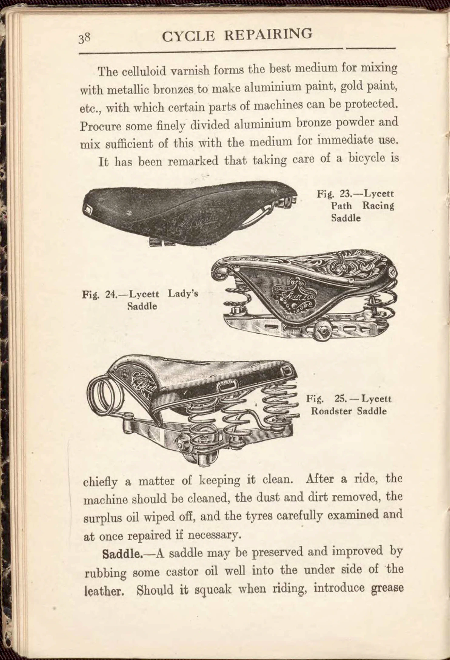
Saddle.—A saddle may be preserved and improved by rubbing some castor oil well into the under side of the leather. Should it squeak when riding, introduce grease
Fig. 23.—Lycett Path Racing Saddle
Fig. 24.—Lycett Lady’s Saddle
Fig. 25.—Lycett Roadster Saddle
[Three pictures of Lycett saddles: the Path Racing Saddle, the Lady’s Saddle and the Roadster Saddle, set in the middle of a paragraph on cleaning a bicycle. The Lady’s and Roadster saddles are shown from the side with coiled springs and clips. The page number is at the upper left and the dark edge of the book shows along the left margin.]
— Page 51 —
OVERHAULING A BICYCLE 39
between those parts of the springs, etc., that come into contact when the rider is pedalling ; should this fail, try lapping the springs with tape or string should the noise be very noticeable. Typical saddles are illustrated by Figs. 20 to 24.
Tool-kit and Repair Outfit.—The tool-kit should be overhauled to see that all necessary tools and the repair outfit for tyres (see p. 43) are in order.
[A short text page on the saddle and on the tool-kit and repair outfit, with only eight lines of print at the top and the rest of the page blank apart from a few small specks and faint show-through of two ring-shaped drawings from the reverse side. The dark edge of the book shows along the right margin.]
— Page 52 —
CHAPTER II
Tyre Cover Repairing
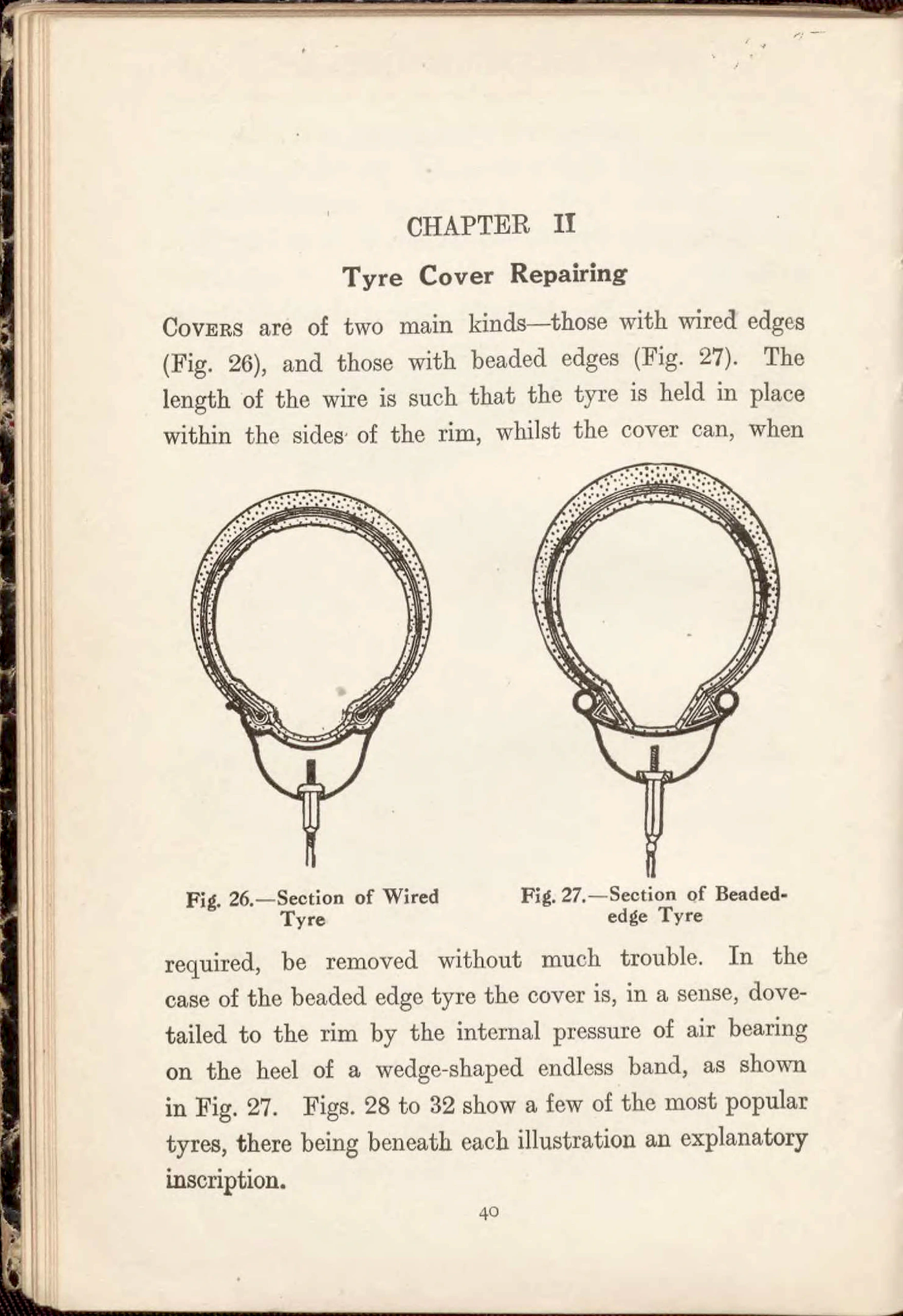
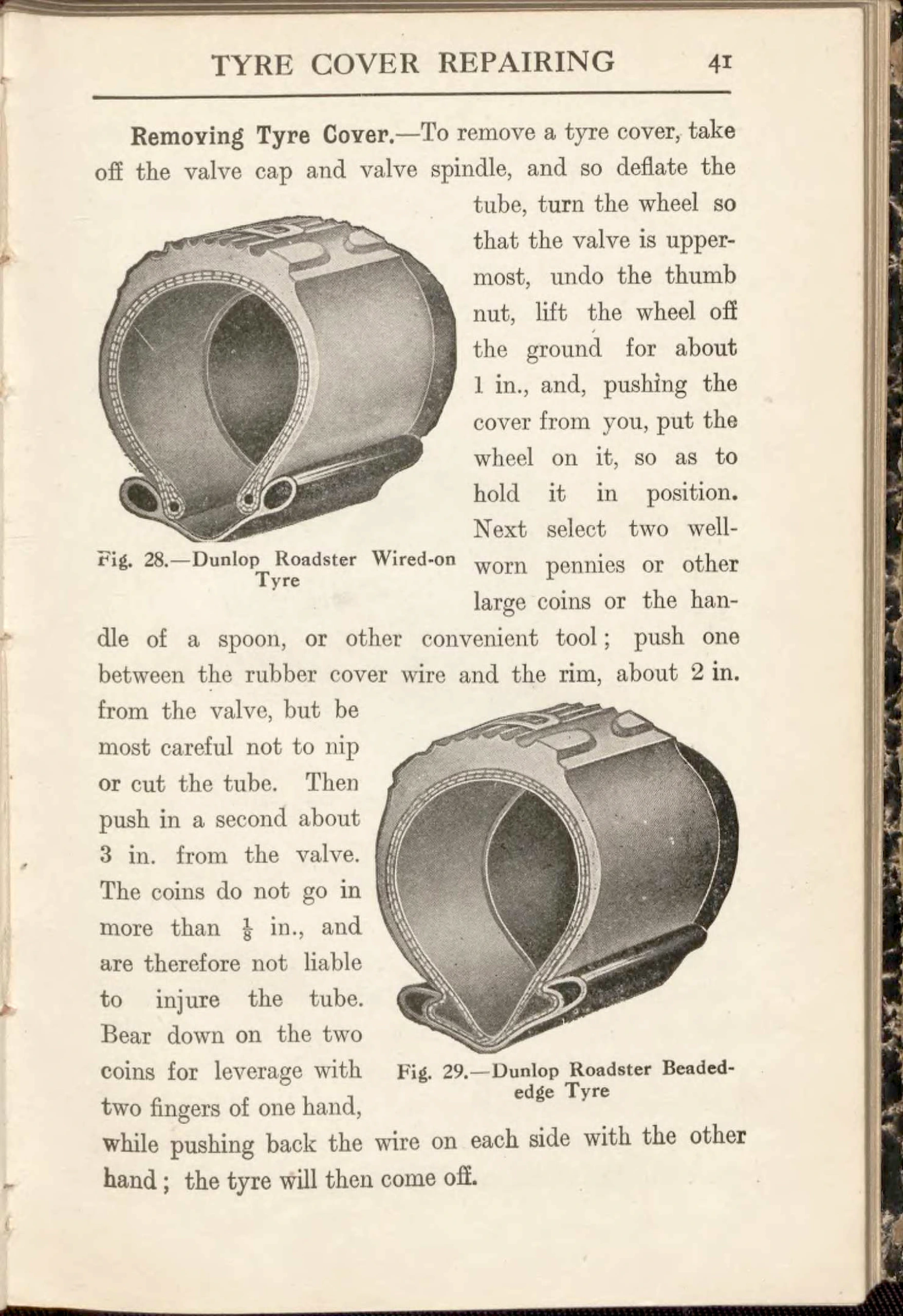
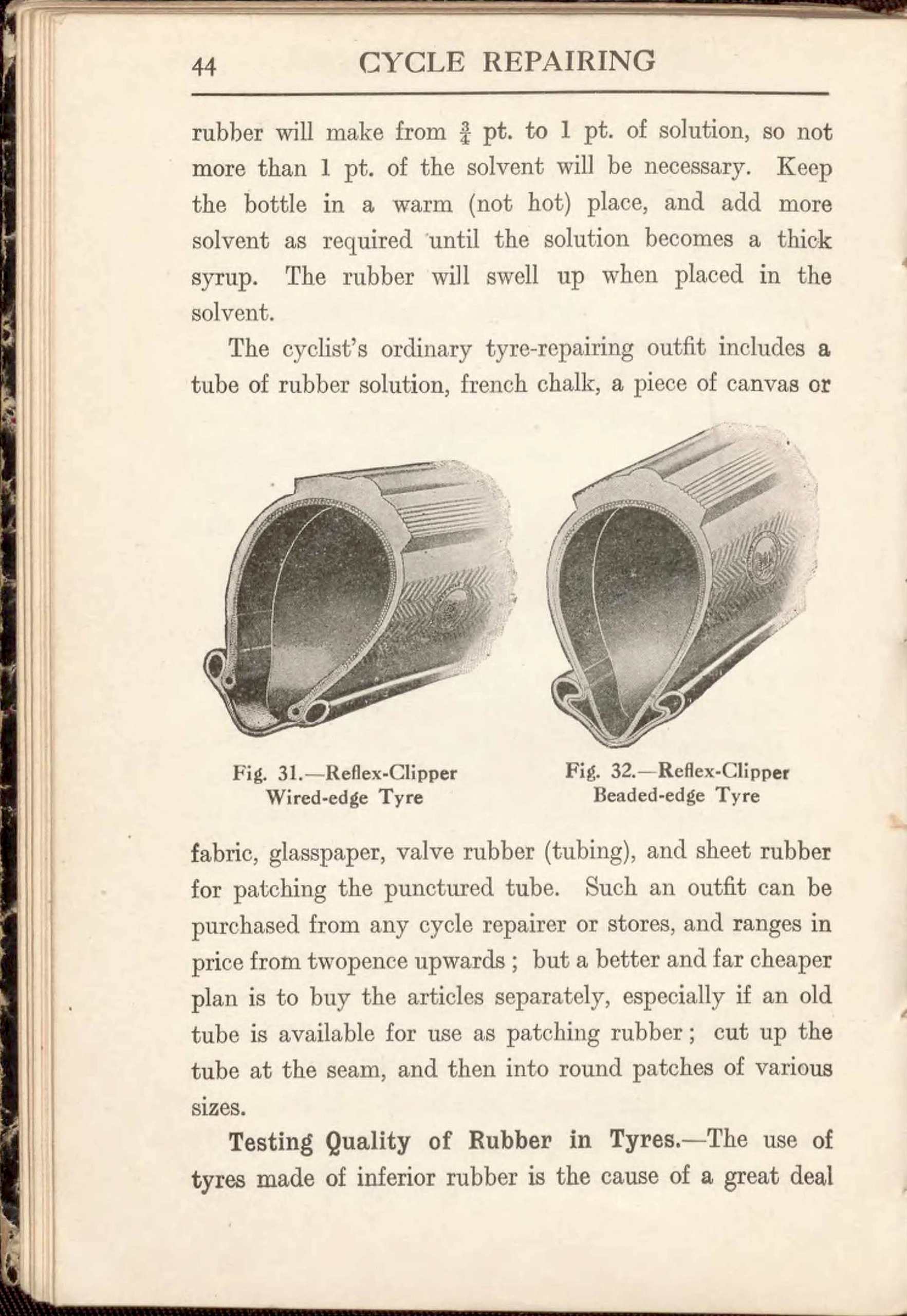
Covers are of two main kinds—those with wired edges (Fig. 26), and those with beaded edges (Fig. 27). The length of the wire is such that the tyre is held in place within the sides of the rim, whilst the cover can, when required, be removed without much trouble. In the case of the beaded edge tyre the cover is, in a sense, dovetailed to the rim by the internal pressure of air bearing on the heel of a wedge-shaped endless band, as shown in Fig. 27. Figs. 28 to 32 show a few of the most popular tyres, there being beneath each illustration an explanatory inscription.
Fig. 26.—Section of Wired Tyre
Fig. 27.—Section of Beaded-edge Tyre
40
[Chapter II, Tire Cover Repairing, opens with one paragraph and two line drawings: Fig. 26, a section of a wired tire, and Fig. 27, a section of a beaded-edge tire, each shown as a ring in cross section on a rim. The page has no running head and the page number is at the foot; the dark edge of the book shows along the left margin.]
— Page 53 —
TYRE COVER REPAIRING 41
Removing Tyre Cover.—To remove a tyre cover, take off the valve cap and valve spindle, and so deflate the tube, turn the wheel so that the valve is uppermost, undo the thumb nut, lift the wheel off the ground for about 1 in., and, pushing the cover from you, put the wheel on it, so as to hold it in position. Next select two well-worn pennies or other large coins or the handle of a spoon, or other convenient tool ; push one between the rubber cover wire and the rim, about 2 in. from the valve, but be most careful not to nip or cut the tube. Then push in a second about 3 in. from the valve. The coins do not go in more than ⅛ in., and are therefore not liable to injure the tube. Bear down on the two coins for leverage with two fingers of one hand, while pushing back the wire on each side with the other hand ; the tyre will then come off.
Fig. 28.—Dunlop Roadster Wired-on Tyre
Fig. 29.—Dunlop Roadster Beaded-edge Tyre
[Two shaded drawings of Dunlop Roadster tires in section: Fig. 28, the Wired-on Tire, and Fig. 29, the Beaded-edge Tire. The paragraph on removing a tire cover is set in narrow columns around the drawings, and the dark edge of the book shows along the right margin.]
— Page 54 —
42 CYCLE REPAIRING
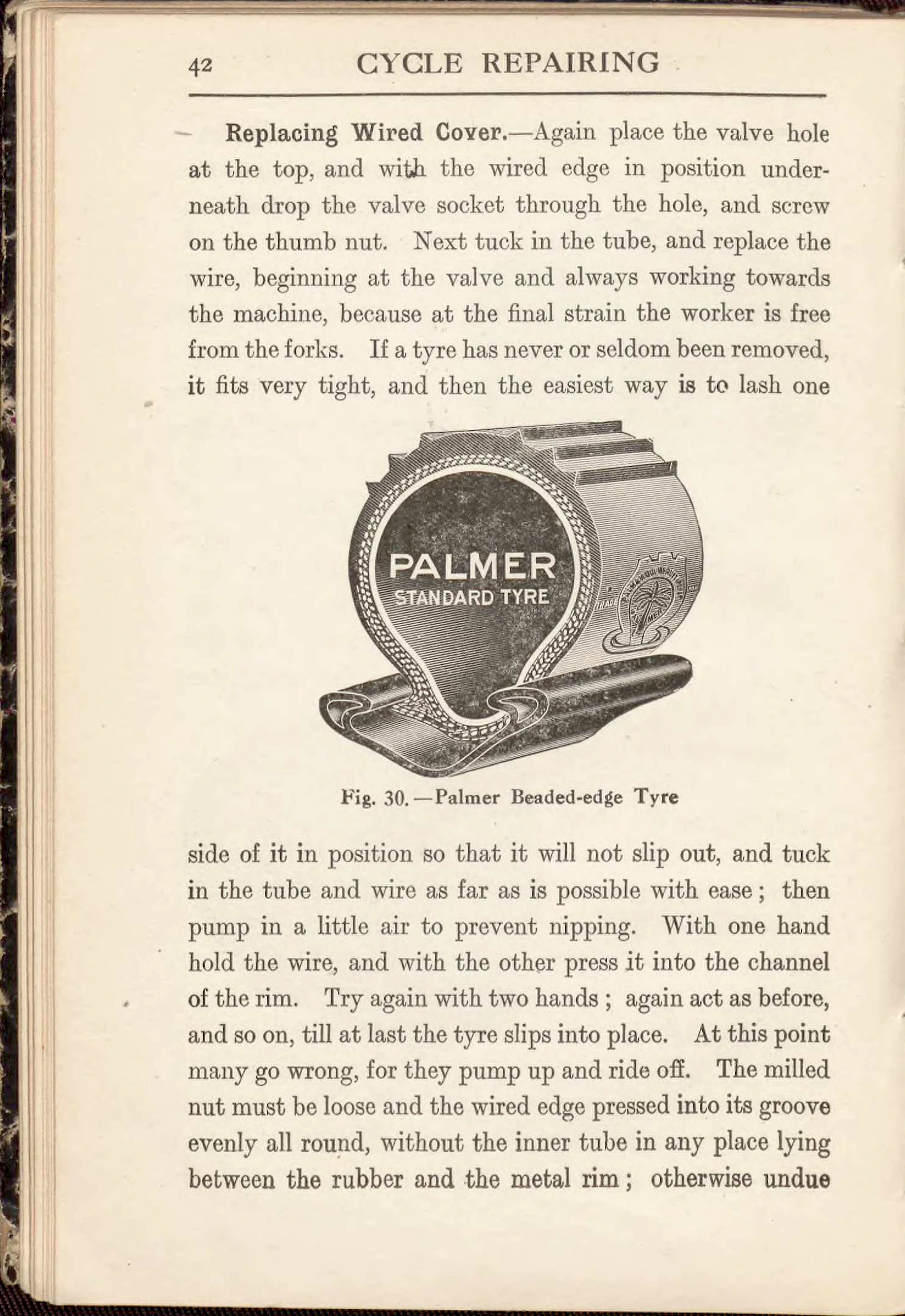
Replacing Wired Cover.—Again place the valve hole at the top, and with the wired edge in position underneath drop the valve socket through the hole, and screw on the thumb nut. Next tuck in the tube, and replace the wire, beginning at the valve and always working towards the machine, because at the final strain the worker is free from the forks. If a tyre has never or seldom been removed, it fits very tight, and then the easiest way is to lash one side of it in position so that it will not slip out, and tuck in the tube and wire as far as is possible with ease ; then pump in a little air to prevent nipping. With one hand hold the wire, and with the other press it into the channel of the rim. Try again with two hands ; again act as before, and so on, till at last the tyre slips into place. At this point many go wrong, for they pump up and ride off. The milled nut must be loose and the wired edge pressed into its groove evenly all round, without the inner tube in any place lying between the rubber and the metal rim ; otherwise undue
Fig. 30.—Palmer Beaded-edge Tyre
PALMER STANDARD TYRE
[A shaded drawing of the Palmer Standard Tire, a beaded-edge tire cut through to show its section on a rim, with its maker’s name in white letters on the drawing and a palm tree trade mark emblem on the side. The paragraph on replacing a wired cover runs around it; a small gray dash mark sits in the left margin beside the first line.]
— Page 55 —
TYRE COVER REPAIRING 43
pressure may cut a large hole both in the tube and cover. When the wire fits properly all round, tighten up the valve and replace spindle, etc., as before.
Tyre repairing is a branch which may be undertaken very profitably by the rider, and a very considerable saving may be effected on the year’s expenditure if tyres are examined frequently and taken in hand as soon as any defect appears. A cover may often be saved from the scrap heap if, when a slight bulge appears, it is at once taken off and properly repaired from the inside, instead of waiting until it develops and finally bursts, making a somewhat lengthy job of what would have been a short one, besides making a nasty gash in the air tube.
Tyre Repairing Outfit.—The repairs to be first described may all be undertaken and successfully accomplished with the aid of ordinary rubber solution, patching rubber, and rubber-proof canvas or fabric.
In purchasing rubber solution, get the best, in ½-lb. or ¼-lb. tins, and not in small collapsible tubes. It is much cheaper bought in the former way, and when there is a good quantity of it at hand one is not so apt to be sparing with the solution—a common error with amateurs.
Many cyclists think it worth while to make their own rubber solution. Here is the method of preparing it. First obtain some pure unvulcanised rubber. (Vulcanised rubber, as from old tyres, etc., cannot be used for the purpose.) With a very sharp knife kept constantly wet, shred it and then place it in a bottle containing either carbon disulphide or benzene (coal-tar naphtha) ; the former solvent has an unpleasant odour. About 1 oz. of
[A page of text on tire cover repairing, with paragraphs on the repair outfit, rubber solution and making rubber solution, and no illustrations. The dark edge of the book shows along the right margin.]
— Page 56 —
44 CYCLE REPAIRING
rubber will make from ¾ pt. to 1 pt. of solution, so not more than 1 pt. of the solvent will be necessary. Keep the bottle in a warm (not hot) place, and add more solvent as required until the solution becomes a thick syrup. The rubber will swell up when placed in the solvent.
The cyclist’s ordinary tyre-repairing outfit includes a tube of rubber solution, french chalk, a piece of canvas or fabric, glasspaper, valve rubber (tubing), and sheet rubber for patching the punctured tube. Such an outfit can be purchased from any cycle repairer or stores, and ranges in price from twopence upwards ; but a better and far cheaper plan is to buy the articles separately, especially if an old tube is available for use as patching rubber ; cut up the tube at the seam, and then into round patches of various sizes.
Testing Quality of Rubber in Tyres.—The use of tyres made of inferior rubber is the cause of a great deal
Fig. 31.—Reflex-Clipper Wired-edge Tyre
Fig. 32.—Reflex-Clipper Beaded-edge Tyre
[Two shaded drawings of Reflex-Clipper tires cut through to show their sections: Fig. 31, the Wired-edge Tire, and Fig. 32, the Beaded-edge Tire. The text on the tire repairing outfit is set above and below the drawings, and the dark edge of the book shows along the left margin.]
— Page 57 —
TYRE COVER REPAIRING 45
of repairing which otherwise would be unnecessary. It should be noted that a high-class cycle tyre tube should be light in weight compared with a common quality of same size and thickness of sheet. The better the quality, the lighter the rubber and the more elastic and tenacious it should be, whereas a common, much-adulterated rubber will be heavy and non-elastic, more or less. A “floating” rubber will float in water, and only the best rubber will do this (solid bulk, not a hollow piece). If a small piece of the rubber is scratched up with the finger-nail, the elasticity can be very fairly tested by a person who is used to it.
Surface Cuts in Covers.—Surface cuts in the tread of the cover are the beginning of nearly all tyre cover troubles, and should be looked for and attended to at once. When the rubber tread gets cut the wet is let into the fabric, which quickly rots, and causes unsightly bulges. With continued neglect, a burst is inevitable.
Where the cut has not damaged the inner fabric of the cover it may be treated from the outside only. Thoroughly clean the cover where to be repaired, by brushing with a stiff brush, get all grit out from the cut, and finally clean it out well with a rag moistened with petrol, benzolene or naphtha, not paraffin. (The last-named soon deteriorates the quality of rubber.) Give the edges of the cut a coat of solution, working it well into the cut ; allow to dry, and give another coat. The cut should then be filled up with a little tyre stopping, which may be purchased at any cycle shop. Press this well into the cut, and allow to stand for at least twenty-four hours before using the machine
[A page of text on testing the quality of rubber in tires and on surface cuts in covers, with no illustrations. The dark edge of the book shows along the right margin.]
— Page 58 —
46 CYCLE REPAIRING
on the road. If the cut is not a very large one and no tyre stopping is at hand, a substitute may be used by mixing up some cotton-wool with rubber solution and pressing this in, after the cut has been prepared as described by giving two coats of solution and allowing to dry. A small piece of unvulcanised rubber compound, as used for vulcanised repairs, makes a good stopping for cuts.
Many cyclists complain that they cannot get a stopping to stay in the cuts after the machine has been used on the road, and generally blame the material used rather than the want of care in doing the job. It must be clearly understood that the cut to be stopped must be perfectly clean before beginning to solution it, and if the edges of the cut are roughened with a small rasp or file it will cause the solution to adhere more firmly. A small curved tyre rasp, very useful for this purpose, can be had for about a shilling or less. One of half-round or oval section with the end curved will be found the most useful pattern.
Deep Cuts in Covers.—Where a cut has gone very deep so as to damage the fabric, different treatment from the foregoing must be used. It is quite useless merely to plug up the cut in the outer surface of the cover if the canvas or fabric has been cut, as if this is not attended to quickly a bulge and burst will result. When the rubber is cut through it lets in the wet, and thus rots the fabric. In this case, then, remove the cover from the rim, and repair the inside first. If the cut is small, clean, and recently done, it may not be necessary to take the cover right off, but only where the cut is. The place should be patched with a suitable-sized piece of proofed canvas,
[A page of text on repairing cuts in tire covers, with a run-in heading on deep cuts in covers. A small round dark speck sits under the second b of the word rubber in line three, and the left margin shows stacked page edges against a dark background.]
— Page 59 —
TYRE COVER REPAIRING 47
according to the size of the cut. Do not be too sparing with the canvas, but cut it amply large enough to give strength to the damaged part. Clean the surface of the cover where the patch is to go with a clean rag dipped in petrol, etc. Give the place and proofed side of the canvas two good coats of solution, allowing the first to dry before giving the second coat. When nearly dry press the patch on and rub well down, so that it adheres firmly. Then treat the cut on the outside as explained above, sprinkle some french chalk over the parts, and replace the tyre.
Weak Places, Bursts, etc., in Covers.—Under this head come such repairs as where the canvas or fabric of the tyre has developed from a neglected cut, and a bulge or enlarged place in the diameter of the tyre has appeared through the fabric giving way partly, and also such repairs as are necessary through the fabric giving way entirely and bursting. In these cases it is quite useless to put on an ordinary patch just a little larger than the burst or weak place, as the patch now has to withstand the whole of the strain in this particular part.
It will now be necessary to cut a patch of fabric some 2 in. or 3 in. longer than the burst or weak place and about 1 in. wider than the cover when flattened out, so that the edges of the patch may be brought over the beads or wires of the cover. This is necessary, as it will be seen that when the tyre is inflated, the pressure of the air tube will hold the edges of the patch between it and the rim, thus relieving the solution of much of the strain that would otherwise be the sole support of the cover in this part. The beads
[A page of text on patching tire covers, with a run-in heading on weak places and bursts in covers. A gray smudge sits in the right margin and a small mark touches the last letter of the word otherwise; the right edge shows stacked page edges and a dark binding.]
— Page 60 —
48 CYCLE REPAIRING
or wired edges will require very well cleaning and solutioning to get a good, firm support at these places.
When repairing such a place as this, the cover should be removed from the wheel and turned inside out during the operation. The repair of the outside or tread will best be done on or off the wheel, according to the nature of the damage. If it is a clean cut or tear without any of the tread being loose from the fabric, it may be done best with the tyre on the rim and partly inflated. But if it is a very bad place and partly come away from the fabric, it may best be repaired off the rim, as the tread must be lifted up to get underneath to clean the surfaces well before solutioning. After repairing and the tyre is on the rim, it is well to partly inflate, bind some tape round the repaired place tightly, and then fully inflate, leaving the tape on until the solution is quite dry and the machine is required for use. The longer it is left before using, the more chance of a permanent repair is the result.
Loose Places in Tread of Cover.—It will sometimes happen that the tread will get loose, or come away from the fabric without any other damage occurring. This, if neglected, will result in the grit and dirt from the road getting in through a cut, and forming a large, unsightly lump in the cover. The best way to treat this is to cut a place in the rubber large enough to work the grit and dirt out, and thoroughly to clean the two surfaces with a piece of rag soaked in petrol on a piece of stick ; but do not begin cleaning until every particle of dirt is worked out. Then a good coat of solution should be worked in through the cut made with a small brush. The two solutioned surfaces
[A page of text on repairing tire covers, with a run-in heading on loose places in the tread of a cover. A few gray specks and smudges lie in the margins, and the left edge shows stacked page edges against a dark background.]
— Page 61 —
TYRE COVER REPAIRING 49
should be kept apart as much as possible until the solution is almost dry, when the parts should be pressed together, the tyre replaced on the rim, partly inflated, and bound with tape and left to set and dry. In this, as in all repairs to the cover, other than the smallest, the machine should not be used for at least a day after finishing, and if left another day so much the better.
Gaiter Patches on Covers.—A weak place or burst may sometimes be very effectively repaired by the use of a gaiter patch, which consists of a piece of fabric wide enough to go right across the cover and lap round the beads to the centre of the cover underneath. They have a thin covering of rubber on the tread, and may be purchased with various pattern treads to match the cover being repaired. They require carefully putting on, or they will come away at the edges and gradually get loose. The surface of the cover must be very carefully cleaned, and it is a great help if the surface is roughened with a tyre rasp before giving the first coat of solution. Two or even three good coats should be given, allowing plenty of time for the previous coat to dry before applying the next. This job is also helped by taping after the tyre is on the rim and inflated.
In purchasing the gaiter, select one that is fully long enough to well cover the weak place, as it is useless putting one on only just the length of the bad place, as it will soon start to bulge again each side of the gaiter.
Re-lining Covers.—Where a cover has numerous weak places it may be advisable to re-line it rather than repair with numerous patches. Re-lining a cover will make a very serviceable job of an otherwise weak and almost
E
[A page of text on gaiter patches and re-lining tire covers, with two run-in headings. A printer’s signature letter sits below the last line of text, and a partly cut-off vertical line of small characters runs along the left edge of the image.]
— Page 62 —
50 CYCLE REPAIRING
useless cover, giving it many more months of usefulness. The repairer must, of course, use his discretion as to whether the condition of the tread of the cover is sufficiently good to warrant spending the time on a re-lining job. Rolls of prepared canvas can be purchased cut specially for the purpose for from 9d. to 1s., and about ¼ lb. at least of solution will be required.
Turn the cover inside out, hang it over a piece of wood fixed to the workbench, so that it will hang straight and may be easily handled and turned round as required. Unroll the prepared canvas or fabric, and run it round the cover to get the correct length. It should lap over some 4 in. to 6 in., and the ends should be cut diagonally. Clean the surface of the tyre fabric as previously explained, and give two or three good coats of solution and one good coat to the proofed side of the new material to be used for relining.
When the solution has sufficiently dried, the lining can be put on. This is a somewhat difficult job to do properly, so as to get the lining central. The main thing to watch is to get it started squarely, or it will gradually run off and work to one side, so that there is not sufficient material to turn over the bead or wire at one side and too much on the other. It is as well for the beginner to get assistance by having the end held out straight whilst laying on the first part. Proceed by getting a start as squarely as possible, laying on lightly in the centre only first until it is seen that a square and even start has been made. Then press down to the edges for a foot or so, leaving the turning over of the beads or wires until the last. Be careful to press
[A page of text on re-lining tire covers with prepared canvas, giving prices and quantities and the method of laying on the lining. Small gray specks lie in the text area, the running head rule shows a slight break, and the left edge shows stacked page edges against a dark background.]
— Page 63 —
TYRE COVER REPAIRING 51
down the centre first, working outwards to the edges. This is to avoid air being trapped between the cover and the lining.
When the end has been reached it will be necessary to give the part where the joint is to be made three or four coats of solution, as being on the back or unproofed surface, the solution will sink in with the first two or three coats. When the joint has been made, turn the cover back right side out, and trim off the edges with scissors if there is any superfluous material here. It is only necessary to have sufficient to lap round the beads or wires without showing the lining when the cover is on.
Before turning the edges over it will, of course, be necessary to clean the surface and give two coats of solution as far as the turned-over parts will come.
The surface of the inside of the cover may now be given a brushing over with french chalk and the job is finished ; but do not use the cover for a day or two if possible.
Some prefer to bring the lining to the edges of the cover only, trimming them off flush with the scissors, instead of bringing them right round the beads or wires. This makes a somewhat neater job, but is not so strong as if brought right round.
Fixing Bands or Treads to Covers.—The life of a cover may be greatly prolonged by fixing a rubber band or tread, which may be applied to a new cover that is likely to get a deal of hard wear, or to a cover that has worn thin on the tread but has a sound casing. Bands are not particularly difficult to fit, and may be purchased cheaply either in the endless form or in the length to be
[A page of text on finishing a re-lined tire cover and on fixing rubber bands or treads to covers, with a run-in heading. The right edge shows stacked page edges and a dark binding, and a few small specks lie in the margins.]
— Page 64 —
52 CYCLE REPAIRING
joined up on the cover. The endless variety is most satisfactory when on, though somewhat more difficult to fit.
Endless Bands.—The under surface of the band should be well cleaned with petrol, and roughened with a tyre rasp or wire brush. The surface of the tyre will require to be treated the same, and if the cover has a prominent pattern on its surface it will be necessary to rasp this off for the width of the hand to be fixed. This job is best done with the tyre on the wheel fully inflated.
Before solutioning the cover or the band, try the band in place to see how much stretch there is in it, and be very careful when fixing it on finally that this stretch is not exceeded in any one part, or it will be found when the last part comes to be fixed down that there is a surplus which cannot be got rid of, except by cutting the band or removing all or part and beginning again.
Turn the band inside out, and give at least two good coats of solution, and also to the cover. When the last coat is sufficiently dry, lay the half of the band on (still inside out), then reverse when the half is on and fix the other half. Only just the centre of the band should be pressed down until the whole of it is in position. Then work round gradually towards the edges ; but do not press these down until the solution appears to be almost dry.
When fixing these bands the wheel should be held in the forks of the machine, or some other suitable support in which it can be held firmly and revolved as required.
Roll Bands.—First remove all the dirt and mud possible with a good stiff brush, rub a rag or cloth dipped in petrol round the cover, and roughen the tread of the cover with
[A page of text on fixing endless bands and roll bands to tire covers, with two run-in headings in italics. A few small specks lie in the margins, and the left edge shows stacked page edges against a dark background.]
— Page 65 —
TYRE COVER REPAIRING 53
a file or rasp. The tyre is now ready to receive its first coat of solution. Apply the solution with a small brush, with which it can be rubbed into the cover better than with the fingers. While the solution is drying or getting tacky, clean the band and cover it with solution in the same way, taking special care that the solution is well applied round the edges of the band. By this time the cover should be ready for its second coat of solution. This should be rubbed on a little lighter, so as not to disturb the first coat. Give the band another coat, and allow this to remain for about an hour to get dry. The band will now be ready to fix on the cover. Two pencil marks round the cover will form a guide when fixing on the band, if a guide is necessary. Roll up the band, apply the end of it to the cover, and unroll the band about 3 in. or 4 in. at a time on to the tyre. If the band is too long, cut off the remainder, so that it makes a neat joint. Press down the band from the centre and work to the edges to remove all air bubbles.
[A single paragraph of text on applying a roll band to a tire cover, filling the upper part of the page, with the lower part blank. The right edge shows stacked page edges and a dark binding.]
— Page 66 —
CHAPTER III
Tyre Tube Repairing
Testing Tube for Small Punctures.—Slightly inflate the tube and immerse it, for about 6 in. to 8 in. at a time, in water contained in a bowl or pail, slightly stretching the tube while immersed. Go carefully round the tube until a leakage is manifested by the air bubbles rising to the surface. Now mark the puncture carefully with an indelible pencil. A netted bag is sold in which to envelop the air tube whilst being tested ; the cost is about a shilling. By this means the tube can be inflated much more than is otherwise possible, and the location of very small punctures is facilitated.
Patching Tubes.—In fixing a patch on a punctured tube, do not be content with simply rubbing off the sulphur and chalk from the surface with glasspaper, but clean it thoroughly with petrol before applying two coats of solution. This also applies to the patch ; and do not be in too great a hurry to fix the patch, but allow time for the solution to dry to the proper “tackiness.” When executing a roadside repair resist the temptation of hurrying the job to get going again, and allow ample time, as the job may have to be done all over again before many miles have been covered. There is no hard and fast rule as to the length of time to give solution to dry, as some makes take longer than others ; but it should be remembered that 90 per cent.
54
[The opening page of the chapter on tire tube repairing, with run-in headings on testing a tube for small punctures and on patching tubes. A small dark fleck sits near the top right corner, faint show-through of print from the other side of the leaf appears near the top, and the left edge shows stacked page edges against a dark background.]
— Page 67 —
TYRE TUBE REPAIRING 55
of failures are through not giving sufficient time. Ten or even twenty minutes may with advantage be given.
Changing Position of Valve.—If the inner tube has suffered badly in the way of punctures round about the valve; or is found to leak under the old seating, it is best to select a new place for the seating. To remove the old valve, take off the two lock nuts and plug, unscrew the nut, and take off the metal washer; the valve stem now can be easily pulled out. Solution over the hole a patch a little larger than the old seating. When the new position of the valve has been selected, cut a hole about 3/16 in. in diameter, in the centre of the under side of the air tube; cut a piece of patching rubber, about 2½ in. by 1¼ in., to the shape of an elongated diamond, and cut a 3/16-in. hole in the centre of it. Clean thoroughly on both sides, and also the surface of the air tube where the rubber patch is to go, with petrol. Solution the patch on one side, and the surface of the air tube round the hole to correspond. When nearly dry, press the two together, with the hole in the patch true with the hole in the air tube. The head of the valve may now be wetted (to assist insertion) and pushed into the air tube, and the metal washer put on and the nut screwed up tight. The job will be strengthened by solutioning a piece of thin linen fabric over the patch before putting on the washer and nut.
Leaky Joints.—It will sometimes happen that a joint in the tube is faulty and consequently leaks. Do not be tempted to repair this with a patch, as it seldom holds, the air escaping along the edge under the patch. The best way to effect this repair, other than taking the joint apart
[A page of text headed Tire Tube Repairing, beginning with the end of a paragraph about time for drying and continuing with the sections Changing Position of Valve and Leaky Joints. The marbled edge of the binding shows along the right side of the scan.]
— Page 68 —
56 CYCLE REPAIRING
and re-making, is to undo about three parts of the joint, roll it back, clean, and well solution the two surfaces before bringing them together again.
If it is desirable to take the joint wholly apart, proceed as follows: With a brush apply a little petrol to the joint, keeping the tube slightly stretched; on contact with the solvent the old cement will be dissolved and the tube will be found to separate. Turn one end inside out for about 3 in., clean it, and put some cylindrical object of a suitable size into the turned back piece. Be careful that the tube is not twisted. Clean the outside of the other end and draw this end over the other one to within 1½ in. of the extremity of the first one. Then coat with solution and lay aside to get tacky. Double one end back over the other, and allow sufficient time to dry. Then remove the cylinder from the tube, and pull the inner tube out straight; the joint is now complete.
A Puncture “Stopping” Method.—For mending small punctures, an American writer has recommended a device consisting of a large darning needle with its point inserted into a wooden handle. There are two pins also in the handle, projecting from opposite sides, and the top of the needle is cut off, leaving the end of the eye open. The idea is easily grasped. To mend a puncture, stretch elastic rubber bands over the pins and through the slot in the end of the needle as tightly as possible until judgment shows that there is enough rubber to fill the puncture. Then insert needle and rubber through the puncture in the tyre, throw the rubber off the pins, and withdraw the needle. The rubber being tightly stretched will contract when
[A page of text headed Cycle Repairing, continuing the section on leaky joints and giving the section A Puncture “Stopping” Method. The marbled edge of the binding shows along the left side of the scan.]
— Page 69 —
TYRE TUBE REPAIRING 57
released, filling the puncture and leaving a small lump inside and outside of the tyre. The outside lump will soon wear off. Before inserting the rubber it is well to reamer the hole smooth by heating the needle with a match, and then searing the edges of the hole.
Valves.—The type of valve with which most tyres are provided is of the Woods pattern, shown in Figs. 33 to 35.
Fig. 33.
Fig. 34.
Callouts: H J G
Fig. 35.
Callouts: B C F D F E A H J K G L M
Figs. 33 to 35.—Woods’ Valve
The stem or plug of the valve and its sheath of indiarubber are shown by Fig. 34. The complete valve is shown in section by Fig. 35, in which A is the body of the valve with a circular head B; between this head and the lipped plate C the air tube of the tyre is pinched by the nut D. The lips F F rest in the wheel rim, and the nut E, on being screwed tight against the inside of the rim, holds the whole valve firmly in position. The valve plug G is shown
[Three engraved views of the Woods’ Valve with a chain: a complete valve in Fig. 33, the stem and its rubber sheath in Fig. 34 and a section of the valve with lettered parts in Fig. 35. The marbled edge of the binding shows along the right side of the scan.]
— Page 70 —
58 CYCLE REPAIRING
in section by Fig. 34; the projecting ears J J fit into slots in the end of the body of the valve, and thus the plug is prevented from turning. The sleeve K screws on to the body A and holds the plug in position; this plug has a small hole drilled nearly through it lengthways, and another hole through the side meets this as shown. When the dust cap L is removed from the stem the inflator can be screwed on in its place; the air is forced through the small hole, and by stretching the rubber reaches the tyre tube. When the force of air ceases the rubber closes over the small hole in the side of the plug. When the tyre is pumped up sufficiently hard, unscrew the inflator and replace the dustcap. To deflate the tyre unscrew the sleeve K two or three turns and draw the plug G outwards, and the air will escape. M is for attaching the dustcap chain.
Leaky Valve.—A valve may leak at three places: where it is fitted to the air tube, between the main part and the removable piece, and at the extreme point of the valve when the cap is removed. The first may be caused by the nut not being tight enough to hold the head of the valve down on the seating. The remedy is to tighten the nut. Or it may be caused by the head of the valve having cut into the tube. In this case re-fit the valve in a fresh place, and fix a patch over the old valve hole. To fit the valve, cut a circular hole ⅛ in. in diameter, wet the head of the valve, and push it through. Solution the under side of the valve tab and also the surrounding surface of the air tube, then press the tab down.
The second and third are caused by a perished or torn
[A page of text headed Cycle Repairing, continuing the description of the Woods’ valve and giving the section Leaky Valve. The marbled edge of the binding shows along the left side of the scan.]
— Page 71 —
TYRE TUBE REPAIRING 59
valve rubber. The remedy is a new valve rubber, but sometimes reversing the old one will answer.
Valve leakage is occasionally found to be due to a piece of grit under the valve rubber, or the rubber not covering the small hole in the valve stem properly.
Repeated Bursting of Tube.—Repeated bursting of a tube is probably due to careless replacement of the tyre; or it may be that the tube is too big. Repair the burst, and inflate the tube until it assumes a circular shape. Place the valve stem through the hole in the rim, and tuck the tube all the way round into the bed of the rim. Then slip the cover on as far as it will go; probably there will be an obstinate portion about 12 in. long. Opposite this part place the two thumbs in between the rim and the cover, and slide them in opposite directions. This will enable a little more of the cover to be slipped on. Repeat this until the cover slips into place. Before inflating, glance round the tyre, and see if the tube is nipped anywhere. Tighten the valve nuts, and inflate the tyre until only a slight impression can be made by pressing with the fingers.
Defective Valve of Single Tube Tyre.—In the event of the valve spring of a single tube tyre having become weak and failing to keep the pin up to its seating in the valve, unwind the brass wire which secures the metal part of the valve in the rubber neck. The metal part can then be pulled out and the valve taken to pieces. It will be found that the movable part has rested; clean this by scraping, and replace. If the spring should be found to be too weak or broken, replace it with a new one, or pull
[A page of text headed Tire Tube Repairing, giving the end of the section on leaky valves and the sections Repeated Bursting of Tube and Defective Valve of Single Tube Tire. The marbled edge of the binding shows along the right side of the scan.]
— Page 72 —
60 CYCLE REPAIRING
out the old one a little to strengthen it. If the valve is a pin with a conical rubber head, this will be all that is necessary; but if it has a brass head, this should be ground in to its seat with a little crocus and oil, or a little “Globe” or “Matchless” metal polish.
Cold Vulcanising Tyre Repairs.—There is a process of cold vulcanising which those who are not content with the effects of ordinary solutioning may care to put to the test. In ordinary vulcanising, rubber mixed with sulphur is maintained at a good heat until chemical reaction is complete, and the properties of the rubber have altered in several important particulars. There is now on the market a number of small steam-heat vulcanising plants designed to meet the requirements of motorists, who find that patches stuck on with solution alone are quite unreliable. Vulcanisation converts rubber cement into a material almost identical with the tyre itself, and obviously greatly increases the strength of the joint; but hot vulcanisation is out of the question in the case of the huge majority of repairs to ordinary cycle tyres. Possibly, however, cold vulcanisation would prove successful if rapidly and skilfully carried out. The agent employed is a solution of 1 part of sulphur chloride in 12 or 15 parts of carbon bisulphide (the latter is also a well-known solvent of rubber). Experiment should proceed on the following lines: Apply a solutioned patch in the ordinary way, and then cover the patch and the edges with the solution.
Another suggestion is to get the rubber-solutioned part of the tyre and the patch to the critical state of tackiness, have both ready to come into contact, coat one of them
[A page of text headed Cycle Repairing, giving the end of the section on the defective valve and the section Cold Vulcanising Tire Repairs. The marbled edge of the binding shows along the left side of the scan.]
— Page 73 —
TYRE TUBE REPAIRING 61
with the vulcanising solution, and press together without wasting a second. Success by this method is not promised, but the experiment is worth trying.
Porous Tubes.—A common method of improving a porous tube is to pour into it, through the valve hole, a quantity of rubber solution made sufficiently thin by mixing with benzene. Turn the tyre about so that the solution runs all over the inside, and continue the twisting and turning until the solution begins to set, then leave the valve open for a day or so. It will be necessary to half inflate the tube immediately after introducing the thin solution. The method is likely to prove a messy business. It has been said that the introduction of french chalk into the tyre (using a small funnel) not only stops up the pores, but preserves the inside of the tube.
Keep Tyres in the Shade.—When making a halt on the road, see that the tyres are protected from the sun, by standing the machine in the shade as much as possible. For if the stay is a lengthy one, some of the patches on the inner tube may lift slightly, and prove very difficult to repair, as the escape is so slight that it often can be detected only by stretching under water. Vulcanised patches would be free from this risk.
[A page of text headed Tire Tube Repairing, giving the end of the section on cold vulcanising and the sections Porous Tubes and Keep Tires in the Shade, with the lower third of the page left blank. The marbled edge of the binding shows along the right side of the scan.]
— Page 74 —
CHAPTER IV
Cycle Enamelling and Plating
This chapter will give information on taking down a machine for re-enamelling and plating, a job which any amateur can tackle, and one for which very few tools will be required beyond the ordinary tools which every cyclist generally possesses. Moreover, it is a job on which a considerable saving in expenditure is made over the usual practice of delivering the complete machine to the cycle agent to deal with.
In large towns, now, there are always firms that do enamelling and plating for the trade, and who will undertake the work for a customer who is not in the trade, provided he prepares the parts properly for them. Although not charging the regular trade price, they do the work for much less than would be the case in the ordinary way. The amateur will have the satisfaction that the work has been thoroughly prepared so as to give the best and most lasting results. Platers must properly prepare the work before they can plate it; but enamel can be applied over almost any surface, but the poorer the surface the poorer will be the final result.
Rusting Under Enamel.—Doubtless the cyclist has often observed the way cycle frames rust under the enamel and gradually blister and throw the enamel off, and has been at a loss to understand the reason of it. The trouble
62
[The opening page of Chapter IV, headed Cycle Enameling and Plating, with the introductory text and the start of the section Rusting Under Enamel, set below a wide blank margin at the top. The marbled edge of the binding shows along the left side of the scan.]
— Page 75 —
CYCLE ENAMELLING AND PLATING 63
is caused by the frame not being properly cleaned bright of all rust before the first coat has been applied; or, even if the frame has been properly cleaned, it has been left to lie about and get rusty; or again, has been handled with damp hands after cleaning.
Examining for Repairs.—Before proceeding to take the machine to pieces, look over it well and see that any necessary repairs are executed before sending the parts away, and not after. A wheel may want truing, a crank or pedal pin straightening, etc., so do any of these before taking down.
Removing the Fittings. — Completely strip the machine of all fittings, and put the parts to be replated into a box by themselves. Take out all bearing parts, bottom bracket axle and discs, front fork from the head, removing the ball races from head unless they are very securely fixed in their places, as they may get knocked out at the enameller’s and lost. Take out the hub spindles and pedal spindles, wrapping the balls from each part up separately and marking them to where they belong.
Some difficulty may be encountered in removing pedal spindles from the cranks, as generally one is put in with a right-hand thread and one with a left-hand thread; but not always in the same way by all makers, some putting the left-hand threaded pin on the left side and some on the right. Some early pattern machines have right-hand threads to both sides, so it will be well to be sure which threads are used before forcing them, as they may be only forced up tighter. Should they prove very difficult to
[A page of text headed Cycle Enameling and Plating, giving the end of the section Rusting Under Enamel and the sections Examining for Repairs and Removing the Fittings. The marbled edge of the binding shows along the right side of the scan.]
— Page 76 —
64 CYCLE REPAIRING
remove, no harm will be done if they are left in the cranks ; but the platers prefer them removed.
Removing Handle Grips.—Tyres must, of course, be removed from the rims and grips from the handle-bars. The latter is a job that requires care, as the grips may very easily be spoilt in getting them off the bars. They are generally fixed on with solid-tyre cement hot, and must therefore be made hot to remove them. One way to do this is to hold the bar in the gas flame, as near to the grip as possible without burning the grip. They are mostly celluloid now or celluloid tipped, and therefore very inflammable. Do not hurry the job, but let the heat work up to the end gradually, then twist the grip off with the hand. Another way is to put it into hot water until the cement is softened ; but as this also softens the celluloid, care is required in taking off, or the grip is spoiled. If the grips are of the cork variety and somewhat the worse for wear, it will be advisable to fetch them off without ceremony and fit new ones ; they are cheap enough.
Preparing Parts for Plating.—It is not necessary, as is sometimes commonly imagined, to polish up the parts with emery-cloth before sending to the plater’s. It is only necessary to wipe the greasy parts, and take every part to pieces that is possible. Remove all nuts, pins, screws, etc., and send them detached. Do not put nuts back on the spindles, etc., but leave them loose.
Taking Wheels to Pieces.—If it is decided to have the hubs replated, this will necessitate taking the wheels to pieces and, of course, rebuilding them. If this is considered too difficult a job, and the plating is not very badly
[A page of text on cycle plating with the run-in headings Removing Handle Grips, Preparing Parts for Plating and Taking Wheels to Pieces; no illustrations.]
— Page 77 —
CYCLE ENAMELLING AND PLATING 65
worn, it may be advisable to let this part go with a good clean up with some good metal polish. Taking a wheel to pieces and rebuilding is, however, not very difficult, and by the aid of instructions given in an earlier chapter, the work may be tackled by anyone with average ability.
Making List of Parts.—When all the parts to be sent to the plater’s are ready, a list should be made of every part to accompany them, and a duplicate kept for checking off when they are returned, as the platers sometimes lose small parts in the vats, and then declare they were not received ; so be precise with this list. Mention each part separately, except the very small screws and nuts, which may be listed as so many small screws and so many small nuts, etc. When the goods are returned, check them off carefully with the list before starting to use any of them, and at once apply for any that may be missing. If the front-fork crown is to be plated, the forks should be cleared of the old enamel before sending. Brake blocks should be removed, and if badly worn, new ones procured.
Parts for Enamelling.—The parts for enamelling can now be taken in hand. These will comprise the frame, forks, mudguards (if any), and the wheels. If the hubs have gone to the plater’s, the wheels must wait until they are rebuilt, when they can be sent with the frame, etc. The rims in any case will have to be cleaned of all the old enamel.
Removing Old Enamel.—There are several ways in which the old enamel may be cleaned off the various parts. Where a lot of such work is done, the old enamel is stripped
[A page of text on cycle enameling and plating with the run-in headings Making List of Parts, Parts for Enameling and Removing Old Enamel; no illustrations. A printer’s signature letter F is printed at the bottom left.]
— Page 78 —
66 CYCLE REPAIRING
off by placing the work in tanks of hot potash ; but this will, of course, be outside the scope of the amateur undertaking one set of work only. Many scrape the enamel off with a blunt knife, finishing with emery-cloth ; but this is a slow process, and may be improved on if a brazing blowpipe or blow-lamp is available. Heat about 1 ft. at a time until the enamel is soft, and then scrape off ; or if a wire brazing brush is at hand, brush it off with this. The blowpipe and wire brush is quite a satisfactory method, especially when getting round the lugs and awkward places, where cold scraping would be very tedious. This method is said to be injurious to the tubing ; but it is not so, as the heat used tends to release any stresses which may be present in the steel caused by the vibration and constant use and hammering on the road. The heat should not be sufficient to make the lightest tube at all red, but just sufficient to soften the enamel.
The use of a chemical enamel-remover is possible, but not customary. For this, dissolve 1 lb. of common caustic soda in 1 gal. of water, and apply this hot ; allow to stand for a short time, then wash off with hot water and a brush. Take care that the caustic soda does not get on the hands, as it has a powerful action on the skin.
Polishing.—When all parts have been thoroughly freed from enamel and cooled down, finish off with emery-cloth, using No. 2 or No. 2½ first, and finally polishing off with FF or O, well scouring the tubes lengthwise and finishing off round the lugs with narrow strips of cloth used crosswise.
Now the finish and appearance of the enamel will depend
[A page of text on removing old enamel and polishing cycle parts with the run-in heading Polishing; no illustrations.]
— Page 79 —
CYCLE ENAMELLING AND PLATING 67
mainly on the smoothness of the finished surface of the work to be coated ; the very best of enamelling will look poor if applied to a rough surface. Therefore, the higher degree of finish that is put on the work before enamelling, the better will be the ultimate result. After the final polishing, dust and rub over with a clean piece of linen rag dipped in turpentine, and after that do not handle the tubes with the bare hand, but wrap some paper round a convenient part for handling. If a very highly finished, glass-like appearance is required, as seen on new high-class machines. the work must be hand polished after the final coat ; but this will, of course, be charged extra for. It is not every enameller who can undertake hand polishing, as it is generally done by women who do nothing else ; but most large firms will do it if specified for.
Precautions.—Precautions must be taken that the threaded parts, such as the inside of the bracket, lubricator holes, etc., do not get filled up with enamel, as this will be found very troublesome when re-assembling, especially if taps are not available with which to clean out the threads. Wooden plugs or corks should be screwed into these parts to keep the enamel from getting in. Another item which may be overlooked is that when the pin and nut which hold the top of the back stays to the seat lug are removed, there is no support for the back forks, and it may happen if the frame is roughly handled that this part may get badly strained and out of truth, so it is as well to fit a dummy pin and nut in this part to prevent this.
Re-assembling the Parts.—When the parts have been received back from the enamellers and platers and
[A page of text on enameling finish and precautions with the run-in headings Precautions and Re-assembling the Parts; no illustrations.]
— Page 80 —
68 CYCLE REPAIRING
checked off, proceed to re-assemble as follows : Put the spindles back into the wheels, oiling with some good oil at the same time. Re-fit the tyres, if they are air-tight and covers sound. Now take the back frame, fit the pin and nut to the back stays and the seat lug first.
Next fit the lubricators to the bracket, then the chain-side bracket disc. Fit the bracket axle, balls, and other disc. Then fit on the cranks and the chain wheel, seeing that the cranks are in line and the cotter pins properly fitted. Adjust the bearing until there is no shake, and lock up with the disc cotters. Next assemble the pedals, and screw up tightly into the cranks. If the pedal pins have not been removed from the cranks, assemble the pedals before fitting the cranks and chain wheel on to the axle.
Now fit the back wheel in position, put on the chain, and adjust up. If the machine has fixed mudguards, fit the guard before putting in the wheel. Fit the front wheel in the fork, and assemble the head parts. Then fit the brake parts to the handle-bars, fix the grips, and put the handle-bars in place.
The other parts can now be fitted up as desired, and with a general run round all nuts and screws and final adjustment of seat pillar and handle-bars, the machine is ready for the road again, and should look as good as new.
Affixing Transfers.—To preserve the original appearance of the machine and make it look finished, one or two transfers of the makers will be required. These can generally be obtained from the makers of the machine free if
[A page of text on re-assembling a cycle and affixing transfers with the run-in heading Affixing Transfers; no illustrations.]
— Page 81 —
CYCLE ENAMELLING AND PLATING 69
written to and a stamped envelope sent for return, the number of the machine given, and saying that the machine has been re-enamelled. The enameller will fix them on properly if told just where they are required ; or if it is preferred to fix them at home, a little good gold-size is required. Place the transfer face upwards on a flat surface, and give the pattern only a thin, even coat with a small camel-hair brush. Let this stand until almost dry, so that it only just feels ” tacky ” when touched with the finger tip. Place in position, carefully press down, and rub firmly all over with a piece of rag, being very careful not to move the transfer in its place, or it will be spoilt. Now damp the surface of the transfer with a sponge and warm water for preference, and after two or three minutes lift one corner and peel off. When quite dry give the surface of the transfer a coat of the gold-size or transparent varnish. It should be stoved to set the varnish properly ; but in the absence of a stove warm the back of the work over a gas jet, being careful not to make it too hot and so blister the gold. Do not be in too great a hurry to put the transfer on after gold-sizing it, but let it get a good dry ” tack ” before applying. Ninety per cent. of failures in transfer fixing are caused by not giving the gold-size time to set properly. Should it appear rather too dry, slightly warm the surface of the work before putting on the transfer.
The fixing of transfers is a fairly simple operation when the surface to which the transfer is to be applied is a flat panel or a round bar ; but in the case of a mudguard, where the surface is parabolic, it is very difficult to press
[A page of text on fixing makers’ transfers to a re-enamelled cycle; no illustrations.]
— Page 82 —
70 CYCLE REPAIRING
paper into perfect contact and keep it there. It will pucker more or less round the edges and refuse to sit. The operation, however, may be carried out successfully if the following plan is adopted. Procure a rubber strip about 2 in. wide and 1 ft. 6 in. in length (a piece of the inner tube of a tyre is just the thing) ; then with a harness-maker’s leather punch make a number of holes through this rubber strip, and having laid on the transfer, proceed to wind the strip over it as a surgeon winds a bandage round an injured limb. As the rubber is stretched in the winding, it will press the transfer evenly and keep it pressed all the time in contact with the sized surface. The object of the holes in the strip is to allow of evaporation of the size or fixing varnish. It is often good to make a few slits round the edge of the transfer when the surface to be decorated is very convex.
Trade Method of Stove-enamelling a Cycle.—As this handbook will almost certainly get into the hands of many workers who have the use of a stove or oven capable of being heated to 500° F. and large enough to take a cycle frame, instructions will now be given on the trade method of enamelling a machine.
A separate room will be required for the enamelling, as it is impossible to obtain clear results if it is carried out in a shop where other work is in progress—that is to say, work of a nature to create dust, dirt, or vibration. Good work cannot be expected if the least dust is in circulation. The room need not be large or very lofty, as long as there is accommodation for the stove and a work-bench, and room to move about conveniently. The room should be
[A page of text on applying transfers to a convex surface and on the trade method of stove-enameling a cycle, with the run-in heading Trade Method of Stove-enameling a Cycle; no illustrations.]
— Page 83 —
CYCLE ENAMELLING AND PLATING 71
free from draughts, and be regularly swept out once a week, including the roof, walls, floor;[?] and bench, while the inside of the stove should be wiped out with rag moistened with turps. The rods and hooks should also be wiped over frequently, and the floor sprinkled with water before beginning work. It is also necessary that the clothes of the operator should be free from dust.
The stove should be of a size adapted to the quantity of work likely to be done. For a repairer or agent, a stove holding from two to three sets will be sufficient, and this should be fitted with the necessary heating arrangement to enable a heat of at least 400° F. to be obtained. The handiest and cheapest form of heating for small stoves is gas, using atmospheric burners ; where gas is not available, a large blow-lamp may be used for the very small stoves. The stove should be fitted with a thermometer reading to about 500° F., so attached that the mercury bulb is inside the stove ; or the whole thermometer may be hung inside, and a small plate-glass panel let into the door through which to read it. A ventilator should be fitted in the top of the stove, with means of opening and shutting. The usual sheet-iron flap over the top of the ventilating pipe is not recommended, as it is liable to cause dust to fall inside the stove when being opened and shut. A plain open pipe is better, with a piece of thin board or enamelled sheet iron as a cover, which can be gently lifted on or off without creating dust. If the inside of the stove is left uncoated, it quickly rusts and causes rust particles to fall on the least shaking or knocking ; it should therefore be coated over with any old enamel or japan, the rods and hooks by
[A page of text on the stove-room for cycle enameling, covering the room, the stove, heating and ventilation; no illustrations.]
— Page 84 —
72 CYCLE REPAIRING
means of which the work is suspended being treated in the same way.
The work-bench should be covered with sheet zinc, and should be carefully dusted and wiped over with a paraffin rag at least once a week. A stand of some kind is handy for wheel enamelling ; one that will hold the wheel by the spindle, or by passing a rod through the hub, so that the wheel may be revolved thereon, is preferable.
Suitable brushes, enamel and enamel pots, complete the outfit. The best form of brush is a flat camel-hair about 1¼ in. to 1½ in. wide, with the hair set in tin, separate brushes being kept for first and second coatings. To use one brush for both coatings is mistaken economy. The brushes must be kept very clean and free from dust. If frequently used they may be left in the enamel, but when only occasionally handled they should be washed out in turps and put carefully away. In any case they should be thoroughly washed out at regular intervals, first in turps and afterwards in very hot water with soap and soda, or a strong soap powder, such as Hudson’s dry soap or ” Compo ” soap powder, working the soap well into the roots of the hairs. They should be rinsed and dried thoroughly before being used again.
Tin enamel pots, such as salmon or preserved-fruit tins, well cleaned out, may be used, and a piece of stout spoke wire should be fitted across from one side to the other, about two-thirds up from the bottom, for wiping the superfluous enamel off the brush and for supporting the brushes when left in the enamel. A small hook should be screwed into the brush-handle, at such a height that when the brush
[A page of text on brushes, enamel pots and a work-bench for cycle enameling; no illustrations.]
— Page 85 —
CYCLE ENAMELLING AND PLATING 73
is suspended by it the end of the brush will not quite touch the bottom of the pot.
Care is required in selecting a good make of enamel, which should be obtained from a reliable manufacturer. First-coating and finishing enamels cost about 6s. per gal., and can be had in ½-gal. tins, ready for use. The finishing enamel, however, generally requires thinning down, with turpentine for preference. The correct thinness can only be found by practice. When the enamel is of the proper consistency, the brush works freely and smoothly over the tubes ; when too thick, it causes the brush to drag on the work, and tends to pull out the hairs. It is important that the enamel should be kept in a suitable warm place, such as on a wooden shelf near the stove ; do not keep it on a cold stone or brick floor. When the enamel has been open in the pot a considerable time it may become dirty. It will then be necessary to strain it through fine muslin or a linen rag before clear work can again be produced.
Bear in mind that the higher degree of finish that is put on the work before enamelling, the better will be the result. The work should be well rubbed down with emery cloth, both coarse and fine, say No. 2½ or No. 3, and then finished with No. 1 ; and the lugs and sharp corners should be well polished with strip emery. In large cycle works the frames are bobbed before enamelling, and thus given a highly polished surface to receive the enamel. When the frame, etc., has been thus prepared, it should be thoroughly dusted with a linen rag ; a fluffy cotton rag must not on any account be used. All holes and corners should be well
[A page of text under the running head Cycle Enameling and Plating, about choosing, keeping and thinning enamel and rubbing down the work before enameling. There are no illustrations.]
— Page 86 —
74 CYCLE REPAIRING
dusted out, and finally wiped over with a linen rag and a little turpentine.
Immediately after the work has been finally wiped over, apply the first coat, starting, in the case of a cycle frame, at the fork ends, inside the back forks and stays, thence to the down tube, top and bottom tubes, and finishing off at the head. Sufficient enamel should be taken up on the brush to cover properly and to work freely without dragging. If applied too freely it will be likely to ” ribble,” or lumps will form on the lower parts in the stoving. When thoroughly coated, hang at once in the stove out of the way. The first coat should be hung the opposite way to the finishing coat—that is to say, a cycle frame should be hung head downwards with the first coat, and fork ends downwards with the finishing coat, so that any surplus enamel likely to form lumps when stoved hard will be on the under side. In hanging the work, arrange it so that no tube hangs quite horizontally.
Stove for one hour at 380° F., leaving the ventilator open for the first five minutes or so after lighting the gas and closing the stove. Carefully hang the work up with the wire hooks or rods running across the top of the stove, without any scraping movement. If the work requires shifting, lift it gently, and do not slide it along the rod. The less handling the work has after being finally wiped over the better—in fact, some enamellers use a glove to avoid the moist hand coming in contact with the work. Close the door slowly, so as not to create a draught or dust.
After the first coat has been stoved hard, it should be rubbed down with powdered pumicestone and water until
[A page of text under the running head Cycle Repairing, about applying the first coat of enamel to a cycle frame and stoving it. There are no illustrations.]
— Page 87 —
CYCLE ENAMELLING AND PLATING 75
all inequalities are removed, using a piece of old alpaca for the purpose. Take care that the corners and edges of the lugs are not rubbed bare, or the parts will show up brown after the finishing coat ; also remove all dust from the rubbing-down process. The smoother the surface is prepared by this rubbing-down process the higher will be the finish of the last coat. It can be over-done by using too much pumice or exerting too great a pressure, thus rubbing through the enamel to the bare steel in places, which are likely to show up brown when finished.
Two coats are generally employed in finishing, though on first-class work, and work that is to be hand-polished, three coats are sometimes given, one with first-coating enamel and two with second or finishing enamel. Proceed in the same manner as in the first-coating, taking special care to cover all parts evenly, and to remove any brush hairs or dust specks before hanging the work in the stove. Stove at about the same heat for one and a quarter to one and a half hours.
If the foregoing instructions have been carefully observed, the work should come out fairly smooth with a high finish. The glass-like surface, however, seen on high-grade cycles, absolutely free from any speck on the enamel, can only be obtained by hand-polishing after the finishing coat. This is done by rubbing down lightly any inequalities with pumice powder and water, which is thoroughly washed off. The surface is then polished with powdered black rotten-stone and water, which is finally worked off with the bare hand until a high degree of polish is obtained. an old piece of silk being used for finishing off.
[A page of text under the running head Cycle Enameling and Plating, about rubbing down the first coat and applying and hand-polishing the finishing coats of enamel. There are no illustrations.]
— Page 88 —
76 CYCLE REPAIRING
The process of re-enamelling a cycle at home necessarily differs from the above, as described in the next chapter
Method of Cycle Plating.—It is out of the question to give in this handbook full instructions on cycle plating. An amount of information on various electrical matters would have to be given, and there is no space for that in this book. ” Electro-plating ” (a companion ” Work ” handbook) should be consulted if a working guide to cycle plating is required. But inasmuch as this book will be read by a large number of people in the cycle trade as well as by amateurs, it is desirable to sum up the chief points in the execution of high-class plating. Complaints concerning the durability of nickel-plating on cycles are common enough, but they were not so frequent in the early days of the cycle boom. The plating then, in general, was of a superior quality, besides which cyclists rode principally for pleasure, and consequently during inclement weather well greased and wrapped up their machines. Many platers contend that rustless plating cannot be done in nickel, but a worker of long practical experience in the trade asserts that for all ordinary purposes it can. Some firms are trying to get over the difficulty by using silver instead of nickel. Silver, however, is not suitable for this purpose ; it is too soft, and therefore liable to abrasion, not to mention the extra cost.
Much bad work is due to careless polishing. All articles, unless in very good condition, should be passed over three grades of emery on suitable bobs. For circular work, such as handle-bars, etc., the soft felt bobs adapt themselves
[A page of text under the running head Cycle Repairing, beginning with a note on re-enameling at home and then a run-in heading, Method of Cycle Plating, on nickel plating and polishing. There are no illustrations.]
— Page 89 —
CYCLE ENAMELLING AND PLATING 77
readily to the contour of the article. For flat work, such as cranks, nuts, etc., the leather-covered wood bobs need no improvement. After being properly manipulated on these bobs, the articles should then be finished with a grease mop and flour emery, and afterwards with a dry lime mop, when the surface can be examined and any defective place made good. The metal deposited will not cover up or hide the least scratch ; if anything, it will make it more glaring. Bobs and mops should always be kept in a dry place, and should be true both vertically and laterally. Covered bobs especially should be carefully examined to see that the leather has not become detached.
When the articles are polished, they can be transferred to the hot potash and cleaned and scoured in the usual way, and immediately transferred to the copper bath. The ordinary cyanide solution, used hot, in an iron tank, not galvanised, gives best results at about 150° F. If it should be found that the work comes out discoloured, add a little ammonia. If the conductivity is such that when the work is in the vat the solution does not ” boil ” up and become covered with a creamy-looking foam, a little cyanide of potassium will put things right. Leave the articles for about half an hour in the coppering bath, which, if in good condition, will soon be covered with the creamy lather mentioned. In the time stated there will be a very good deposit. Remove the goods into the hot water, and dry off in hot sawdust.
Now pass the parts on to the polishing machine, and bring them to a high polish, and once more return to the potash to be cleaned. This will discolour the surface, but
[A page of text under the running head Cycle Enameling and Plating, about polishing with bobs and mops and then cleaning and copper plating in a cyanide bath. There are no illustrations.]
— Page 90 —
78 CYCLE REPAIRING
a minute in a cyanide dip will restore that. Pass the articles on to a separate scouring bench and clean well with a soft brush and rotten-stone, rinse off in clean water, and get them into the nickel solution at once.
Difficulties with nickel solutions can easily be avoided by using the best materials, the right electro-motive force (6 volts), and a resistance board. A solution made up with the best double salts of nickel and ammonia, kept slightly acid with best sulphuric acid, will remain in good condition and work well if ordinary care is exercised to keep out dirt and foreign matter. A 100-gal. bath was in use for six years with less than a quarter of an hour’s attention a week, apart from cleaning rods and anodes. The work, when put in the bath a second time, should remain in it about three hours. Then finish off and polish as usual.
Keep dust and dirt out of the solutions by covering them when not in use, and have the plating shop a reasonable distance from the polishing machines for the same reason. Have as much light as possible on the vats, but keep the direct rays of the sun from them. Keep the nickel solution as near 600° F. as possible. Use the resistance board carefully. Nickel, to be tough and durable, must be deposited at a slow rate. As soon as the extremities of the work begin to turn a dark colour, lower the current passing. In the latter stages of cleaning articles, do not touch them with the hands. Do all wiring up on the scouring bench before swilling off.
[A page of text under the running head Cycle Repairing, about nickel plating solutions, the resistance board and keeping the plating shop clean. There are no illustrations; faint show-through of the text on the other side of the leaf appears in the lower part of the page.]
— Page 91 —
CHAPTER V
Re-enamelling a Cycle at Home
RE-ENAMELLING a cycle at home without the aid of a stove to harden the enamel is not particularly difficult. Of course, it must not be expected that the ultimate result will be the same as, or the work wear so well as though the cycle were properly stove-enamelled ; but a very good result may be attained if care is used all through, and the job is not hurried or scamped in any way. Good work requires time and attention, and in this particular branch the ultimate result depends very largely not only on the care and attention in carrying it out, but in a very great measure on the preparation of the surface of the material to be treated.
Enamels.—The materials used on a job of this kind are entirely different from those used in the stoving process, as in the latter a special stoving enamel or japan is used, which will not set or dry without the heat of a japanning stove ; but by the process to be described, either one of the proprietary cycle enamels put up in 6d. and 1s. bottles, and to be obtained at most cycle depots, must be used, or best carriage black japan, or the ordinary flat colours used by carriage painters, and afterwards varnished.
The first-named method, common cycle enamel, will probably prove the simplest, but will not give the best results. Avoid a spirit black, that is, one made up with
[The opening page of Chapter V, Re-enameling a Cycle at Home, with an introductory paragraph and a run-in heading, Enamels, on the materials used. There is no running head or printed page number, and the upper part of the page is blank apart from faint show-through of the text on the other side of the leaf.]
— Page 92 —
80 CYCLE REPAIRING
spirit. Frequently, these blacks dry too quickly ; in fact, some of them dry before they can be properly laid on, and consequently produce an uneven, patchy appearance that never will look well. Moreover, the surface will chip with the slightest provocation, and soon look shabby. These spirit blacks are only suitable for touching up, where some part has become chipped or rubbed, such as the edges of rims, mudguards, etc. Probably the best results will be obtained by using carriage painters’ flat colours, and varnishing for the finish. This will look better and wear better than any other method if properly done.
Touching Up.—A word or two here will be in place on the item of touching up, as even this may as well be done properly.
The most frequent cause of the necessity for touching up is rust, which forms on the surface of the steel where the enamel has become thin or worn, and allowed the damp to attack the metal. Before the parts are touched up, the rusty places should be thoroughly rubbed down with emery-cloth until the metal appears bright, taking care not to scratch the surrounding portions of the enamel that are not to be coated, as the scratches will show through the new enamel put on, especially if coarse emery-cloth is uscd.
Where a badly chipped place on a prominent part is to be touched up, the object to attain when rubbing down is not to leave any sharp edges of the old enamel surrounding the rubbed-down portion, as this shows up quite plainly when dry. The edges should be rubbed down well, so that
[A page of text under the running head Cycle Repairing, about spirit blacks and a run-in heading, Touching Up, on rubbing down rusty places before touching up enamel. There are no illustrations.]
— Page 93 —
ENAMELLING A CYCLE AT HOME 81
there is no abrupt termination to them ; then the patched place will not be visible.
Preparing the Work.—To make a good job, the machine must be taken to pieces, and all the old enamel cleaned off, as explained in the preceding chapter, in preparing the parts for sending away to the enameller’s. A very important item is the workshop or room in which the job is to be done. The preparation of the work can be done anywhere that is convenient ; but the painting or enamelling requires a suitable room. Dust, cold, or draughts are fatal to good work, so a room must be selected free from these drawbacks. Not only must the room be clean and free from dust, but the workman’s clothes should be free from dust.
The tools must be clean also. These precautions more especially apply to the final varnishing, and for this warmth is particularly desirable. The domestic kitchen with a fire, and the door shut, is a desirable place. A suitable brush or brushes are necessary. A common penny paint or gum brush is not suitable ; but get a 1-in. or 1¼-in. flat camel-hair or similar brush. If this is carefully cleaned after using for the first coating, it can be used for varnish ; but get it perfectly clean, first in turpentine, and then wash well in warm soap and water, and dry before using again.
It may be inconvenient to get a small quantity of suitable materials from the colour and varnish people, and as so little will be required, probably the best way will be to go to a carriage builder’s and get the colours and varnish from them ready mixed for use.
[A page of text under the running head Enameling a Cycle at Home, about preparing the work, the room and the brushes for enameling at home. A printer’s signature letter G is set below the last line, and there are no illustrations.]
— Page 94 —
82 CYCLE REPAIRING
Applying the Enamel.—With the machine taken down and properly prepared by scraping or otherwise, and well rubbed smooth with emery-cloth, rub over the surface with a turpentine rag, to remove any trace of grease, and when quite ready to give the first coat, dust carefully over with a linen rag free from fluff or loose pieces, going carefully into all corners or holes where any dust is likely to lodge. Give the work a good, even coat, not put on too thickly so as to run, and hang up to dry. Let this be for twenty-four hours to dry, and harden before giving a second coat.
Before applying the second coat, look over the work well for any brush hairs or rough places, which should first be removed. Let the second coat dry as before, and again examine for blemishes. If a little gold-size or varnish is mixed with the flat colour it will allow the surface to be rubbed down very lightly with a little powdered pumice on a damp cloth. This will give a nice, smooth surface on which to give the finishing coat of varnish. This should be put on evenly and with a good flow, but not too thickly, or it will run and look unsightly when dry.
The remarks referring to care in freedom from dust and dirt of any kind, either in the room or the work or tools, specially apply to the varnishing process, as do the remarks regarding the warm room being free from draughts. Do not start to assemble the machine until the enamel is quite dry and hard. The longer it is left to harden before handling the better; it should be left for two or three days if possible.
Transfers should be fixed and any lining done before
[A page of text from the chapter on enameling a cycle at home, with a bold run-in heading “Applying the Enamel” and four paragraphs. There are no illustrations; the dark edges of the book’s leaves show along the left margin.]
— Page 95 —
ENAMELLING A CYCLE AT HOME 83
varnishing, but do not attempt any lining unless skilled in that particular branch, as it is much more difficult than it looks, and unless done properly entirely spoils the look of the job.
In doing the wheels do not forget the inside of the rims, and see that all rust is rubbed off with emery-cloth before painting. It is not necessary to give the spokes two coats and a final varnishing, as it is likely to make them have a thick appearance, besides being a somewhat tedious job to go over these three times with the brush. Rub the old enamel off with a piece of emery-cloth, dust, and give one coat only of a little colour and varnish mixed. The best way to do the spokes is to begin at the crossing, inside, go all round about 3 in. or 4 in. up, then from the nipples down to where the first left off. Reverse the wheel and repeat; then finally do the outside of the spokes, then the inside of the rim, finishing off on the outside of the rims. The rims may with advantage be given two coats.
Should the hubs be in a rusty state and too bad to clean up, and it is not desired to take the wheels down for re-plating, they may be improved and stayed from further rusting by giving a good clean up to free from all rust, and then giving a coat of aluminium paint (see p. 38).
In assembling the machine be careful in handling, as the appearance of the varnish may easily be spoiled until it is really hard, which will take some days.
Cycle Lining.—A cycle frame is lined or striped after the final finishing of the enamel process. The best work is hand polished before lining. The lining is done with a lining pencil or brush, using ordinary oil colours mixed
[A page of text from the chapter on enameling a cycle at home, with a bold run-in heading “Cycle Lining” and five paragraphs on finishing wheels, hubs and frame lining. There are no illustrations; the dark edges of the book’s leaves show along the right margin.]
— Page 96 —
84 CYCLE REPAIRING
with a little varnish, and kept thin enough to flow from the brush freely with turpentine. The lines are put on entirely by hand without any guide or mechanical aid to accuracy, so that a very considerable amount of skill is necessary to make a good job, and an amateur seldom, if ever, obtains good results. It would be wiser to have the cycle lined by a professional man, as nothing spoils the look of a machine more than amateur lining.
Should, however, the amateur particularly desire to try his hand at the job, let him remember that a new pencil should first be broken in to its work by using it well on several pieces of scrap tube. Otherwise, by reason of the pencil jumping or splaying out with uneven pressure, the lines will not be true. Always give a good sweep in taking the long lines, and begin with the point of the pencil first, working it down until the whole of the face touches. The pencils used are known as sword pencils, a suitable size costing about 8d. each, or 6s. per dozen.
The paint for lining cycles should first be ground with a little pale copal oil varnish, and then thinned down with sufficient of the same varnish to render the paint workable. For stencilling, the paint will have to be made stiffer than for ordinary work, or it will run; but such a paint does not dry with a brilliant gloss like ordinary enamel; still, it will be better than if ground with linseed oil. To get a bright gold line it will be necessary to line in with oil gold-size, and when this is nearly dry, cover with gold-leaf and dust off the excess.
Cycles can be lined by the use of transfer lining paper. The frame is first thoroughly cleaned, and the transfers
[A page of text on lining a cycle by hand, with sword pencils priced at 8d. each or 6s. per dozen, gold lines and transfer lining paper. There are no illustrations; the dark edges of the book’s leaves show along the left margin.]
— Page 97 —
ENAMELLING A CYCLE AT HOME 85
selected and measured off for position. They are then coated evenly and thinly with good transfer varnish, allowed to dry until the right tackiness is reached, placed in position, and rubbed on with a clean dry rag. Then moisten with a clean sponge, and peel off. When dry, varnish, and if possible stove for a short time to set and harden the varnish. The secret of success is to use good varnish and obtain the correct degree of tackiness. Most beginners make the mistake of not allowing sufficient time to dry.
For gold lining, the line is first drawn with gold-size, using the edge of the tube as a guide. The gold-leaf is cut into strips and put on, left to dry, and brushed off with a hare’s foot or cotton-wool. It may be burnished or left dull. A line may be put on with bronze powder mixed in gold-size and varnished over. A white line is put on with a brush, using a quick-drying paint such as Club enamel applied thin. Scroll transfers may be bought for finishing the lines.
[A page of text on transfer lining paper, gold lining and white lines for a cycle, ending the chapter on enameling a cycle at home with the lower half of the page blank. The dark edges of the book’s leaves show along the right margin and faint print from the reverse side shows through in the blank area.]
— Page 98 —
CHAPTER VI
Building a Bicycle from Standard Fittings
Now that cycle fittings are standardised and can be purchased with all machining and drilling ready done for fitting up, the question of building one’s own cycle is not nearly such a formidable task as it used to be. Any amateur mechanic with average ability and the necessary tools should, assisted by the following instructions, be able to build a really first-class machine. Probably the first questions that will be asked are: What tools will be required, and what will be the cost?
Tools Required.—As regards tools, the least that can be done with are a vice, light hammer, mallet, two or three files, rule, spoke-nipple key, hack saw, some means of drilling the brazing peg holes, and a straightedge. If the brazing is to be done at home, of course some means of brazing the various lugs, etc., must be available, either a powerful blow-lamp, not a small plumber’s lamp, but a powerful brazing lamp, or, better still, a brazing forge with blowpipe. In the absence of brazing facilities, the joints may be done by a cycle repairer or smith. The first cycle ever built by the writer was brazed up by a blacksmith for a few shillings.
Cost.—Regarding the cost, probably the main item with many, the great difficulty with amateurs is to get the proper fittings and materials at a reasonable price. Very
86
[The opening page of the chapter headed “CHAPTER VI” and “Building a Bicycle from Standard Fittings”, with text on the tools required and the cost, and the page number at the foot. There are no illustrations; a short thin vertical line shows in the left margin beside the heading “Tools Required” and faint print from the reverse side shows through at the top.]
— Page 99 —
BUILDING A CYCLE 87
few of the wholesale houses will supply amateurs at all, and those who will charge a much higher price than is charged to the trade. To get over this difficulty, the Editor of this Handbook has made arrangements for a Wolverhampton tradesman to supply readers with a selected set of fittings and all materials necessary to complete the machine at a charge of 30s. (In writing the Editor for the address, a stamped and addressed postcard should be enclosed.) All parts are machined and ready to fit together in the easiest possible manner, and are of the very best quality and all of absolutely standard pattern. The set comprises:
Shells.—Bottom bracket machined 1⅛ in. by 1⅛ in. by 1 in. Top and bottom head lugs machined 1¼ in. by 1⅛ in. Seat lug and stay-eyes machined 1⅛ in. by 1⅛ in. Top and bottom bridges machined. Fork crown and ends machined, standard D.
Parts.—Spindle and head clip, pin and nut; bracket cups; cotters; ball races (three); seat pillar, pin and nut; head nut; lamp bracket; fork-end adjusters. All machined finished and heavily nickel-plated.
Tubes.—Three body tubes, eight back-stay tubes, narrow back; one front-fork tube, screwed and slotted; head tube; one pair of D-forks.
Handle-bar and seat pillar finished and plated any shape. Chain wheel, cranks and cotters, four-claw pattern, forty-four to fifty-two teeth by ½-in. Hubs drilled, less cog; Westwood rims, drilled; spokes and nipples, spokes cut and screwed; pedals, rat-trap. All above finished and nickel-plated. Saddle, cork grips, and chain.
[A page of text from the chapter on building a bicycle from standard fittings, listing a set of shells, parts and tubes supplied for 30s. with their sizes. There are no illustrations; the dark edges of the book’s leaves show along the right margin.]
— Page 100 —
88 CYCLE REPAIRING
The after expenditure will be plating fork crown, if thought necessary, enamelling frame and fork blades, and tyres.
Working Drawing.—The first thing to do is to decide on the size of frame required, and make a full-size drawing (Fig. 36). The average-size frame is 24 in., measuring from the centre of the bracket to the top of the seat lug; this suits a rider of 5 ft. 6 in. to 5 ft. 8 in. A shorter or taller rider will require a corresponding shorter or taller frame. Make the drawing full size in chalk on a wall or board. No details are necessary; but simply a line drawing to assist in cutting tubes and fitting up to the correct angle and lengths. Mark the ground line. 14 in. above this describe a 28-in. circle for the back wheel (that is, if 28-in. wheels are decided on), mark the bracket centre 12 in. from the ground line, and at a distance from the back-hub centre to give the centre decided on. Draw a line from the bracket centre to the hub centre to represent the back forks. Knock together temporarily the seat tube into the bracket and all the front tubes and lugs, as this will be the best guide for filling in the other lines to the correct angle to suit the lugs being used. Draw a line through the centre of the head tube parallel with the down tube, to represent the steering angle. In front of, and parallel to, this draw another line at a distance equal to the amount of curve on the front-fork blades. On this line, 14 in. from the ground line, will be the front-wheel centre. The position of the top tube will, of course, vary with the height of the frame being built; but should be parallel with the ground line, unless a racing frame with sloping top tube is desired,
[A page of text under the run-in heading “Working Drawing” giving the steps for a full size chalk line drawing of the frame, with measurements in inches and feet, and a reference to Fig. 36. There are no illustrations; the dark edges of the book’s leaves show along the left margin and a few small ink specks sit near the top right corner.]
— Page 101 —
Fig. 36.—Working Drawing of Bicycle
[A boxed line drawing of a bicycle frame with two large wheel circles, a small bracket circle and a ground line, captioned Fig. 36 and printed sideways on the page with the caption reading upward along the right edge. The drawing carries no letters or numbers and the page has no running head or page number; faint print from the reverse side shows through and a tiny reddish speck sits inside the rear wheel circle.]
— Page 102 —
90 CYCLE REPAIRING
in which case a special top head lug and seat lug drilled at different angles will be required.
Wheels.—It will be best to begin on the wheels, unless the reader has a pair of similar-sized and pattern wheels by him, for this reason. The back wheel will be required for setting the forks and building the frame, and the front wheel will be necessary for a similar purpose for the front forks. The hubs are drilled 40 back and 32 front. The back wheel will be taken first (see Fig. 37). Thread a spoke through one hole in the flange, and another through the next hole. Cross this pair of spokes, and bring them up to the holes in the rim fifteen apart; that is, there should be thirteen vacant holes between the two occupied by the first pair of spokes. Slip nipples on the ends of these spokes, and just screw up a few threads with the fingers. Lace another pair of spokes through the same hub flange opposite the first pair, bring these up to the rim as the first pair, and screw on the nipples. There should now be five vacant holes between one spoke of the first pair and one of the second pair on each side. Turn over the rim and hub, and put in two pairs of spokes on this side in a similar manner to the first. Go carefully round the rim and hub to see that spokes are equally spaced in the rim and hub flanges, and come up to the proper holes in the rim in relation to the holes in the flanges.
If these first eight spokes are all one dead length, which should be ascertained beforehand, the nipples should be screwed down an equal distance on the spokes, so that the hub does not shake about; but there must be no tension on the spokes yet. If this part has been properly done,
[A page of text under the run-in heading “Wheels” on lacing the spokes of the back wheel, with a reference to Fig. 37. There are no illustrations; the dark edges of the book’s leaves show along the left margin.]
— Page 103 —
BUILDING A CYCLE 91
and the spokes are of an equal length, the rim should run fairly true when spun by holding the spindle in the fingers. If this is not so, look for the fault and correct.
With these first eight spokes properly started and rim roughly true, the remainder of the job of putting the wheel together is simple, as when a spoke is laced through the hub flange and brought up to the rim, its length will show at a glance the proper hole in the rim to which it should
Callouts: A B C
Fig. 37.—Building 40-spoke Wheel
go. Put a washer and nipple on each spoke as inserted in the rim, first screwing on with the fingers.
The front hub and rim will be found to be drilled thirty-two holes, and is put together in the same manner as the back wheel, except that the spokes are laced eleven apart instead of fifteen. That is, in beginning the first pair of spokes there should be nine vacant holes between the first pairs put in (see Fig. 38).
When all the washers and nipples are on, go over both
[A line drawing of a wheel hub, three laced spokes lettered A, B and C and a section of rim, captioned Fig. 37, Building 40-spoke Wheel, in the text of a chapter on building a cycle. The text continues across the figure from the top of the page to the bottom.]
— Page 104 —
92 CYCLE REPAIRING
wheels carefully to be sure every spoke is in its proper place before putting any tension on the spokes, or the rim may get badly pulled out of truth.
Trueing Wheels.—When the wheels are assembled, something will be required to true them on. In the absence of a proper trueing stand, the forks may be used for this purpose, after the fork ends have been fitted and brazed in, the ends of the fork blades being held in the vice.
With the wheel fixed in the forks, spin it and first get it to run as true as possible by adjusting the first eight spokes inserted, which should be marked when first put in. When the wheel runs fairly true by these, proceed to screw up all the other nipples in turn, so that there is no slack, but no tension yet. When the wheel has been gone round once, spin it and see if the rim has gone much out of truth anywhere. If it has, it will no doubt be found that a spoke, or perhaps more than one, has been screwed up too tightly, and thus pulled the rim considerably out of truth. If this is so, slack out a little at this point and try again. Proceed as already explained (see pp. 10 to 13).
Take care that the wheel does not get ” dished,” that is, pulled over more to one side than the other. A professional wheel-truer trusts to his eye alone for this ; but it will be best for the amateur to test this with a straightedge or piece of thin string. With plated rims, whiting will be better than chalk, as it will show up better.
When sufficient tension on the spokes has been arrived at can only be found by experience ; but if a true and well-made wheel is available, a good idea may be formed
[A page of text in the chapter on building a cycle, with the run-in heading “Trueing Wheels” and paragraphs on truing a wheel in the forks and testing for dish. There are no illustrations.]
— Page 105 —
BUILDING A CYCLE 93
by feeling this. Two spokes on opposite sides of the wheel should be grasped firmly between the thumb and first two fingers of the right hand. The great thing to obtain is an equal tension on every spoke, otherwise the wheel will soon go out of truth when used.
Before putting the wheels aside as finished, see if any
11 APART.
11 APART
Fig. 38.—Building 32-spoke Wheel
of the spoke ends protrude through the nipples ; if so, file them off flush. Before proceeding to put the wheels together look at the drilling of the rims, and see that the holes on the proper side of the rim are used. The holes are not all drilled alike, but are drilled at a corresponding angle to that of the spokes. It should also be
[A line drawing of a 32-spoke wheel with a hub, four solid and four dashed spoke lines running to the rim, and dashed arrows around the rim, captioned Fig. 38, Building 32-spoke Wheel. Two labels on the drawing read 11 APART, one above the rim and one below it.]
— Page 106 —
94 CYCLE REPAIRING
observed that the wheel, whilst being trued, should be properly adjusted on its bearings, so that there is no shake.
Building the Frame.—Clean out all the lugs free from grease, and then emery-cloth them where a brazed joint is to be made. Serve the ends of tubes and forks the same,
Fig. 39.—Joint Pegged for Brazing
Fig. 40.—Turned Pins or Pegs
as all surfaces to be brazed must be clean and free from scale or rust.
Back Fork Ends.—Clean out the ends of the back forks with a half-round file until bright and free from scale. Level off the end, and fit the fork end in tightly. If the edges of the fork are chamfered off inwards with the file, it will help to make a close-fitting joint. Do not be afraid to make these joints too good a fit in the fear that the brass will not run round the joint, as when it is hot it expands and allows the brass to run freely.
Top and Bottom Stay-eyes.—Fit these to the short
[A line drawing of a frame lug joint with a tube at each opening and small pegs set in its walls, captioned Fig. 39, Joint Pegged for Brazing, beside three small turned pins captioned Fig. 40, Turned Pins or Pegs. Text on building the frame and on back fork ends runs above and below the drawing.]
— Page 107 —
BUILDING A CYCLE 95
top tubes in a similar manner to the back fork ends, and the bottom stay-eyes to the long stay tubes.
Bridge Tubes.—Fit the short stay tubes to the top bridge in a similar manner, and knock the short bottom-bridge tubes on the bridge lugs. These joints are now ready for brazing, if they are all a good knock-on fit ; but if any of them are loose and likely to move, drill and peg with a piece of wire or brazing peg. Cobbler’s round heel brads make very good brazing pegs (see Figs. 39 and 40).
Fitting Head Tubes.—Fit the head tube to the top
Fig. 41.—Setting Back Wheel and Forks
and bottom head lugs ; drill and peg these. Then fit the top and bottom frame tubes to their respective lugs, drill and peg, and this part is ready for brazing. To keep this part firm whilst being brazed, and to ensure them cooling at the proper angle, the bottom bracket and seat lug may be fitted to the down tube, and this used as a stay whilst the head lugs are being brazed, by fitting temporarily the ends of the top and bottom tubes into the seat lug and bottom bracket respectively.
The down or seat tube should, of course, be first cut to correct length, and before brazing, the top and bottom tubes must be true with each other and out of winding.
[A line drawing of a back wheel axle and hub set between two fork blades, with a dotted outline of a fork end beside it, captioned Fig. 41, Setting Back Wheel and Forks. The text above and below covers bridge tubes, fitting head tubes and brazing the frame.]
— Page 108 —
96 CYCLE REPAIRING
This part should also be laid on the drawing, to see that all is correct for angle and lengths of tubes.
Setting Fork Ends.—With the above parts fitted and brazed, the back fork ends should be set before proceeding farther ; and to facilitate handling, the various joints that have been brazed should be filed up, as it is much easier to handle these small parts in the vice now than when the whole frame is fitted together, and there is less likelihood of the tubes getting damaged by excessive pressure in the vice, as there is so much less weight to support.
Clean out the fork-end slots to fit nicely on the back spindle without shake, and set the fork ends true, so that when the forks are fitted up to the bridge the inner faces will be quite parallel with each other. Unless this is quite true when the frame is finished and the hub nuts are tightened up, the spindle will be strained and probably bent, causing the hub bearings to run badly. To test for truth, fix the two forks in place and tighten up the nuts. The ends of the forks should then be of a width equal to the lugs on the bottom bridge, and equally distant from both edges of the wheel rim. Figs. 41 to 43 show the testing of the front bottom tube and the testing of the fork end faces.
Fitting Front Part.—The front part of the frame may now be built up. The bottom bracket and seat lug are fitted to the down tube, and the top and bottom tubes fitted into their respective lugs on the seat lug and bracket. When knocked home, try on the drawing to see that the tube lengths and angles are correct. Then drill and peg ready for brazing. See that the head tube and the down
[A page of text in the chapter on building a cycle, with the run-in headings “Setting Fork Ends” and “Fitting Front Part”, on setting the back fork ends and building up the front of the frame. There are no illustrations.]
— Page 109 —
BUILDING A CYCLE 97
or seat tube are quite true with each other by sighting the edges of the two tubes from the front. Before finally fixing the top tube into the seat lug, put a small charge of brazing spelter and borax into the top tube ; about half a thimbleful will be sufficient. A small air-hole will also be required in this tube, either drilled on the under-side of the tube, or through the top of the seat tube into the top tube.
Air-holes.—When a tube is being brazed that has both ends blocked up, so that there is no air outlet, a small air-hole is necessary to prevent a burst tube or the joint blowing. A very small hole, about 1/32 in., is all that is necessary, and drilled in an out-of-sight position.
The seat lug should
Fig. 42.—Testing Front Bottom Tube
Fig. 43.—Testing Fork End Faces
not be sawn right through until after it is brazed, or it will open when hot and make a bad joint.
Fitting up a Back Part.—Cut the back forks off to length, and be sure to have both equal. The best way to measure these is to cut a piece of wire long enough to
H
[Two engraved drawings side by side, a front bottom tube with a seat lug and a fork with its end faces, each with a dashed outline beside it, captioned Fig. 42, Testing Front Bottom Tube, and Fig. 43, Testing Fork End Faces. The captions are printed sideways and the text wraps around the left of the drawings.]
— Page 110 —
98 CYCLE REPAIRING
bend over at right angles at one end to fit in the end of the fork-end slot. Then cut off just the length of the fork blade. With this both can be cut to a nicety. Fit the forks to the bridge lugs, and peg and braze. Before finally pegging, drill air-holes and load for brazing the same as the top front tube. Fit the top back stays to the top bridge lugs in a similar manner to the bottom, taking care that both are of equal length. Drill air-holes and load and peg. Before brazing up these and the bottom forks to the bridge joints, fit the wheel in place, and see that the rim is in the centre of the forks and stays. If not, one tube is longer than the other, or the wheel is dished. Whichever the fault, it must be corrected before brazing.
Whilst brazing these bridge joints, stays of some kind must be fixed between the free ends to keep the job firm, and to ensure the joints setting with the forks and stays at the proper angle. In brazing the short stay tubes to the top and bottom bridges previously, the lugs will have become scaled with the heat, so this must, of course, be filed bright again before fitting up. This also applies to the back lugs on the bottom bracket when the front and seat tube joints were brazed. So these must be scraped out clean before fitting the back part up to it.
In cutting the back forks and back stays, it should be remembered that they should be cut at such a length that will give equal clearance from the rim to the under-side of both. The amount of clearance will depend on whether mudguards are to be fitted or not. If with mudguards, there should be quite 1-in. clearance from the surface of the tyre. That is to say, if 28-in. wheels are being used,
[A page of text in the chapter on building a cycle, on fitting the back forks and stays to the bridge lugs, brazing the bridge joints and cutting the back forks to length. There are no illustrations.]
— Page 111 —
BUILDING A CYCLE 99
the distance from the centre of the hub spindle, when right up at the end of the fork slot, should be 15 in. If without mudguards, ¾-in. clearance will suffice ; or for a track racer ½ in. will be ample.
If mudguards are to be secured to the frame with pins and nuts to the bridges, see that the proper-sized holes for the pins to be used are drilled in them before brazing, and that they do not get blocked up with brass in brazing.
With the forks and stays brazed up to the bridges, set and filed up, the back forks should now be fitted to the bracket lugs.
When the short tubes from the bridge to the bracket are cut the proper length, clean the ends and knock them home in the lugs. Before drilling for pegs, test with a straightedge the fork-end faces for truth off the bracket faces. They should be equally distant from these faces. If not, pull over one fork at a time until they are, keeping the two fork ends the proper width apart to fit on the hub without spring. When this is correct, drill and peg. Then fit the top stays in place and braze.
In brazing the back lugs of the bracket, it will be best to braze the one nearest to the worker first. If the one farther away is done first, it may become partly unbrazed whilst doing the nearest one. It must also be watched that whilst brazing the first of these lugs, the second one does not get scaled with the heat. To avoid this, put some borax on the joint as soon as it becomes red. Before brazing any of the bracket lugs, the screw threads should be protected by painting with blacklead mixed with water or oil.
[A page of text in the chapter on building a cycle, on mudguard clearance, fitting the back forks to the bracket lugs and brazing the back lugs of the bracket. There are no illustrations.]
— Page 112 —
100 CYCLE REPAIRING
Front Forks.—Drill the fork ends to fit the hub spindle or shoulders of the cones (if any), and cut to length with the same exactitude as the back forks. Set the ends, and try on the wheel for truth. When fitted on the wheel and the hub screwed up, the top ends should be the exact width to fit in the crown. If they require setting and the forks are stiff, do not set them in place, but remove from the hub spindle and bend in the vice, or the spindle may get bent. Clean out the crown hole for a 1-in. tube; fit the tube and braze. Clean out the D-holes for the forks after brazing in the tube. Clean and fit the fork blades to the crown, try on the wheel again before drilling to see that the wheel rim is exactly central in the forks, and that the steering tube is true with the wheel. This can be tested with the straightedge placed alternately on each side of the rim, using several parts of the rim in case the wheel is not dead true. When this is all correct, drill and peg. Before pegging up, load the two blades with spelter and borax, as before mentioned. The amount of clearance between the under-side of the crown and the surface of the tyre will be the same as for the back part.
In fitting the steering tube to the crown, fit it so that the slotted part comes exactly central with the back of the crown, and before brazing the blades to the crown test for truth, the blades being parallel with each other. The best way to do this is to place a straight rod through the spindle holes, and another on a straightedge on the front of the blades close up to the crown. The two should then be exactly parallel. If not, one blade will require pulling forwards or backwards. Or it sometimes happens, but
[A text page from the chapter on building a bicycle from standard fittings, under the run-in heading Front Forks, on fitting and brazing the fork blades and the steering tube. The text breaks off at the foot of the page in the middle of a sentence.]
— Page 113 —
BUILDING A CYCLE 101
ra[illegible]ely, that the two blades are not of equal curvature. This should be looked for before they are fitted to the crown, by putting the two together and laying them on their back edges on a level surface, when the spindle holes should be exactly the same height. Should they not be perfectly equal in curve, one must be increased in curve, or the other slightly straightened.
When brazing the blades to the crown, stay the ends with the front spindle or other stay to keep the ends the exact distance apart. When brazing, lay the fork on its side on the hearth, with the crown some 3 in. or 4 in. lower than the fork ends. Shake the spelter and borax well down to the crown end, and braze the lower blade, directing the flame on to the crown first until it becomes a dull red. Put some borax on the joint, and then move the flame to the joint, and feed with brass and borax. Let the brass set, then remove and brush. Treat the other blade in a similar manner.
Setting Front Forks.—After brazing the forks they should be fitted to the front wheel, again tested for truth, and set where necessary. They may not require any more setting; but one blade often becomes slightly longer than the other in brazing, thus throwing the wheel rim out of centre in the forks. If this is very slight, which is all it should be at the most, it may be corrected by slightly filing the hole in the fork end at the top on the side to which the rim is nearest. If one of the blades has moved in brazing so much that the rim is much out of centre, unbraze one blade, refit, and rebraze; but if the blades are well pegged and tested before brazing, this should not be necessary.
[A text page from the chapter on building a bicycle from standard fittings, with the run-in heading Setting Front Forks on brazing the fork blades and setting the forks. The first word at the top of the page has a defective letter, shown as a raised dot in the printing.]
— Page 114 —
102 CYCLE REPAIRING
Hints on Brazing.—If a first attempt is to be made at brazing, do not straightaway make that attempt on this job, but practise on some odd pieces of tube and lugs until a satisfactory joint can be made. The main thing is the means of heating the heaviest joint to a brazing heat, and this may be done in several ways, by a paraffin blow-lamp costing about 35s. to 40s., or, what is better, a gas blowpipe ⅞ in. or 1 in. in diameter, with at least ½-in. gas-supply pipe and a fan or bellows to supply the necessary air pressure. If fitting up a cycle-repair workshop and power is available, by all means fit a small fan; it is far preferable to a bellows of any description, the flame being steady and constant, and the operator being able to devote his entire attention to the job of brazing the joint. In the absence of power, obtain a small circular double-blast bellows and hearth, costing about £5 with blowpipe.
The brazing materials are brass spelter, No. 3 size, or brass brazing wire (the writer prefers the former), and powdered borax as a flux; a tin to hold the mixture of spelter and borax, and one for the plain borax; a piece of iron wire about ¼ in. by 18 in., flattened at one end to feed the spelter and borax to the joints; and a brazier’s brush, which is desirable but not absolutely necessary, to brush the superfluous borax and brass from the outside of the joint as soon as it is removed from the hearth. This saves much work in filing up, and saves the files immensely. Do not purchase the borax ready powdered, but buy lump borax, as that purchased ready powdered is much adulterated. In making the brazing mixture, use about equal parts, in bulk, of No. 3 spelter and borax.
[A text page from the chapter on building a bicycle from standard fittings, with the run-in heading Hints on Brazing on the heat source, the brazing materials and the borax and spelter mixture. The fractions in the text are set as small case fractions.]
— Page 115 —
BUILDING A CYCLE 103
In preparing the work for brazing, see that the surfaces are bright, clean, and free from scale. The joints should be a good tight fit, free from shake, and where a joint such as the back forks to the bridge lugs is being made, see that the tube edges fit close up to the shoulder of the lugs all round, and do not depend on the brass to fill up a badly fitted joint.
In brazing the joint the chief things to observe are to make a sound joint the full depth of the lug, and not merely to get a thin film of brass round the outer edge. To do this the flame should be directed on to the thickest part of the lug first before getting the tube too hot, and feeding the joint with borax before the metals get hot enough to scale. As soon as the lug and tube begin to get a dull red feed with borax only, then with brass and borax, when it should flow almost like water and penetrate to the deepest part of the joint.
Another very important thing is not to “burn” the tube by getting it too hot, which will spoil it and cause an early fracture. If the above method of heating the lug first is observed, and the tube near the lug kept “wet” with borax to prevent it scaling, this should not happen.
Where a joint is being brazed which lends itself to inside loading, the work should be so placed on the hearth
Fig. 44.—Serrated Liner
[A text page from the chapter on building a bicycle from standard fittings, on preparing and brazing a lug joint, with a line drawing labeled Fig. 44.—Serrated Liner. The drawing shows a tube with a zigzag serrated edge at one end and sits in the middle of the page, between two lines of the same paragraph.]
— Page 116 —
104 CYCLE REPAIRING
that the brass inside, when it melts, will tend to flow to the outside of the joint. Then if borax only is used on the outside until brass appears round the edges, it will be fairly certain that a sound joint will result. As soon as this comes through, feed a little brass-and-borax mixture to the joint, and as soon as ever this melts, stop the flame and remove from the hearth. If the flame is kept on too long after this there is a possibility of “soaking” all the brass out of the joint, especially so if the joint is not a very good fit.
Some braziers use the blacklead mixture for protecting thin tubes whilst brazing; but if this is used, care must be taken to keep it out of the actual joint, as brass will not adhere to metal where this is present.
When tubes are brazed together end to end, it is well to use a liner, as shown in Figs. 44 and 45.
Filing Up.—For filing up and preparing for enamelling, a vice, files, and emery-cloth will be required. Necessary files will be a 10-in. or 12-in. bastard, 8-in. half-round ditto, and 8-in. half-round smooth; and a pair of hardwood block or vice clamps will be useful, and prevent the tubes getting damaged by the vice jaws. They are easily made; get a piece of hardwood 5 in. by 3 in. length with the grain. Bore holes as required through the centre, and
Fig. 45.—Section of Jointed Tube showing Liner
[A text page from the chapter on building a bicycle from standard fittings, on brazing tubes with a liner and on filing up, with a line drawing labeled Fig. 45.—Section of Jointed Tube showing Liner. The drawing shows a lengthwise section of two tubes joined over a serrated liner, and sits between two lines of the same paragraph.]
— Page 117 —
BUILDING A CYCLE 105
saw in halves. Nail a piece of leather on the end for a hinge, and the job is done. Two strips can be nailed on the top to rest on the vice jaws, or the wood can be cut to the necessary shape to provide this.
Great care should be observed when filing up the joint not to cut into the tubes round the edges of the lugs, as this will weaken the tube. Take as little off the tube as possible, only just removing the superfluous brass and borax present. Nos. 2½ or 3 and F emery-cloth may be used wrapped round a piece of wood, and torn into narrow strips to get round corners. Get the best, blue-backed, and not the common white-backed emery-cloth, as it will not stand the work before breaking up.
[A text page from the chapter on building a bicycle from standard fittings, on making vice clamps and filing up brazed joints, with the final paragraphs of the chapter in the upper part of the page. The lower two thirds of the page is blank.]
— Page 118 —
CHAPTER VII
Free Wheels and Coaster Hubs
The free-wheel clutch is a device which, as all cyclists know, allows the pedals to remain at rest when the rider so desires, while the bicycle itself continues to run. It is by no means a new introduction, and, as a matter of fact, had been extensively tried a number of years before it became—about the year 1900—an almost indispensable fitting. There were two types in general use a few years ago—the roller, or friction, in which a friction roller ascended an inclined plane and wedged or locked a fixed and a loose part together; and the pawl and ratchet type, in which the drive is communicated in a positive manner, not by friction, but by the mechanical engagement of a pawl in the teeth of a ratchet ring. The friction type is still in use on thousands of old bicycles, and in numberless cases has given splendid service; but its behaviour when worn or when filled up with gummed oil was liable to be erratic, and this led to the friction clutch being almost entirely superseded by the pawl and ratchet clutch. However, some highly successful patterns of coaster hubs and variable gear hubs of the present day embrace a free-wheel clutch of the roller type; and it is to be assumed that good designing, the use of high-grade materials, and the employment of skilled
106
[The opening page of Chapter VII, Free Wheels and Coaster Hubs, with its text on the free-wheel clutch and the roller and pawl and ratchet types. The page number is printed at the foot of the page and faint show-through of the printing on the other side is visible in the upper part.]
— Page 119 —
FREE WHEELS AND COASTER HUBS 107
methods of manufacture have now resulted in a thoroughly reliable device.
Fig. 46 shows the roller or friction clutch (front plate removed). A is the chain ring; B, ⅛-in. balls; C, roller; D, springs; E, clutch. It will be seen that the clutch is screwed on the hub barrel, and revolves with it. When the chain ring is pulled round in one direction, the five rollers are drawn by friction against the ring up the five inclined planes, and are jammed between the clutch and ring, and the road wheel revolves with it. When the chain ring is held still, as is the case when free-wheeling, the clutch revolves with the road wheel, causing the rollers to run back into the bottom of the inclined planes, where they are kept by friction against the hub ring until pedalling starts again. The blocks F at the back of the rollers are to keep them square, and the small spiral springs keep the blocks up to their work.
Fig. 46.—Roller or Friction Free-wheel Clutch
Callouts: D O F B B A A F O E D
[A friction free-wheel clutch seen from the front with the front plate removed, a toothed chain ring around a ring of balls with five rollers, blocks and springs, lettered on the drawing and captioned Fig. 46.—Roller or Friction Free-wheel Clutch. The drawing sits in the middle of the page between two parts of the same paragraph.]
— Page 120 —
108 CYCLE REPAIRING
In the now almost universal ratchet clutch, the chain ring has a ratchet running round its circumference. Recesses are formed in the clutch, and in these are fitted pawls, which engage with the ratchet while driving. When free-wheeling, the pawls run over the ratchet, as in an engineer’s ratchet brace. In some cases rocking pawls are used, but in most cases the pawls are kept up to their work by a flat or small coil spring (see Fig. 48).
The “Hyde” is one of the most popular pawl and ratchet free-wheels, and the illustration presented by Fig. 47 will enable its construction to be understood easily. It shows the clutch with the outer washer removed. The
Fig. 47.—Hyde Pawl and Ratchet Free-wheel Clutch
Fig. 48.—Section of Sunbeam Free-wheel Clutch
Fig. 48.
[Two engraved views of free-wheel clutches, the Hyde pawl and ratchet clutch seen from the front with its ring of balls and the Sunbeam clutch shown cut in section, with the captions Fig. 47.—Hyde Pawl and Ratchet Free-wheel Clutch and Fig. 48.—Section of Sunbeam Free-wheel Clutch. The Fig. 47 drawing is on the left, the sectioned Fig. 48 drawing is on the right with the label Fig. 48. below it, and the drawings carry no letters.]
— Page 121 —
FREE WHEELS AND COASTER HUBS 109
portion screwed to the hub is made from a solid forging, with a ball-race formed on the inner side, the opposite side being screwed for the purpose of receiving an adjusting cone or washer. The balls form a bearing upon which the chain ring revolves. The outer cone is locked against the face of the portion of the clutch screwed to the hub. Fig. 47 clearly demonstrates the manner in which the drive is effected. The two pawls are each supported by a light spring; this spring throws the pawl into the rack machined inside the chain wheel. When the wheel is being driven by the pedals, the pawl fits into one of the teeth, with the result that the whole of the clutch mechanism revolves together. When free-wheeling, the chain ring is held stationary, and the inner portion of the clutch carrying the pawls then overruns the chain ring.
The Micro free-wheel employs rocking pawls, and is a pattern that has long given satisfaction.
Coaster Hubs
What is known as a “coaster hub” is a combination of rear hub, free-wheel clutch, and pedal-operated brake. It allows of safe “coasting,” inasmuch as the brake is of an extremely strong and efficient pattern. This type of hub has now become extremely popular, and there are many different makes on the market from which to choose.
It is much simpler to remove a back wheel fitted with a coaster hub than when rim brakes are employed, the brake shoes of the latter causing trouble. A coaster hub will be found an ideal brake for a road-racing machine fitted with wooden rims, as the rubber blocks of a rim
[A text page under the running head “Free Wheels and Coaster Hubs”, continuing the description of a free-wheel clutch with pawls, followed by the centered heading “Coaster Hubs” and two paragraphs about coaster hubs. The right edge of the scan shows the stacked page edges and a dark marbled surface beyond them.]
— Page 122 —
110 CYCLE REPAIRING
brake quickly get destroyed, owing to the intense friction. On a machine fitted with rim brakes it is essential, for smooth braking, that the wheels should always be kept perfectly true, as otherwise a faulty braking surface is offered, and the brakes act in a “hit-and-miss” style. Another disadvantage of the rim brake is that the rim soon looks untidy in the paths of the brake blocks, this
Fig. 49.—”New Departure” Coaster Hub
applying to plated and enamelled rims, and not, of course, to aluminium ones.
The “New Departure” (Figs. 49 and 50) is one of the earliest and best known of coaster hubs. The brake is self-contained in the hub, and is applied by a very slight backward pressure upon the pedals. The brake consists of three steel rings which are forced against the shell by means of an internal mechanism. A good feature of the New Departure hub is that it allows of a “tight pedal,” which permits unconscious application of the brake when free-wheeling; and it also allows of the
[A New Departure coaster hub with its brake arm and a chain sprocket, shown in a halftone engraving above the caption “Fig. 49”, between two blocks of text on coaster hubs and rim brakes. The page also shows faint show-through of print from the reverse side near the running head, and the stacked page edges and a dark marbled surface along the left edge.]
— Page 123 —
FREE WHEELS AND COASTER HUBS 111
bicycle being wheeled backwards without the brake coming into action. Providing the hub is kept well lubricated, it will give efficient service over a long period of years. The free-wheel part of the device runs on ball-bearings and is noiseless, there being no pawls and ratchets. When assembling the New Departure hub, the clutch is fitted on an axle so that the triple projections enter the brake box. The cage should now be placed on the clutch with the exposed side of the balls towards
Callouts: A.2 A.12 A.15 A.16 A.5 1/16 A.17 A.21 3/16[?] A.18 A.3 A.14 A.1 A.20 A.6 A.7 A.4 A.13 A.8 A.9 A.10 A.19 A.11
Fig. 50.—Parts of “New Departure” Coaster Hub
the centre of the hub. The clutch sleeve is next placed on to the clutch. The whole of these parts assembled as above are now placed in the hub shell, into which the transfer spring is next placed, care being taken that one of the projections on the inside of the spring fits into the groove on the clutch sleeve. The other ball cage is now on the driver (exposed side of balls towards centre of hub as before), and the driver is placed into position in the hub shell. The cone and nuts are next screwed on the axle and the hub adjusted in the usual manner, that
[The separate parts of a New Departure coaster hub laid out in an engraving, each part marked with a letter and number from A.1 to A.21 and two marked with fractions, with the caption “Fig. 50” between two blocks of text on assembling the hub. The right edge of the scan shows the stacked page edges and a dark marbled surface beyond them.]
— Page 124 —
112 CYCLE REPAIRING
is by means of the cone on the chain wheel side. Ball retainers are fitted to ensure ease of assembling, etc. The hub is made in two widths—the “Regular” for roadster bicycles, and the “A-Narrow” for road-racing and other lightly built machines. The former is 4⅛ in. wide and weighs 2 lb. 3 oz.; the latter is 4 in. wide and weighs 2 lb. 2 oz., complete with chain ring, brake arm, and clip. Chain rings are furnished in the following sizes:—
| Pitch. | Width.
8, 9, 10 teeth | 1 in. | ⅛ in.
7, 8, 9 10, 11, 12 ,, | 1 ,, ¼ | 3/16 ,,
16, 18, 20, 22 ,, | ½ ,, | ⅛ ,,
14, 16, 18, 20, 22, 24 ,, | ½ ,, | 3/16 ,,
11, 12, 13, 14, 15, 16, 17 ,, | ⅜ ,, ⅛ | 3/16 ,,
The “Regular” model is made for any one of the following chain lines: 1⅜ in., 1½ in., 1⅝ in., and 1¾ in.; and for 1 5/16 in., 1 7/16 in., 1½ in., 1 9/16 in., and 1 11/16 in. In ordering sprockets, it is necessary to give chain line, pitch and width, and number of teeth.
The parts of the New Departure hub shown in Fig. 50 are as follow: A1, hub shell; A2, driver; A3, clutch sleeve; A4, spindle without cones or nuts; A5, sprocket lock nut; A6, clutch; A7, axle cone; A8, brake box; A9, brake cover; A10, brake arm with 1 clip and bolt; A11, clip and bolt for brake arm; A11A, adjusting screw for brake arm; A12, transfer spring; A13, spindle nut; A14, washers (two), A15, convex washers (two), A16, ball cage (large); A17, sprockets, 1/16-in. off-set; A18, sprockets, 3/16-in. off-set and flat; A19, spanner; A20, ball cage (small).
[A text page headed “Cycle Repairing” finishing the assembly of the New Departure coaster hub, with a table of chain ring sizes by number of teeth, pitch and width, a paragraph on chain lines and a run-in list of the hub parts shown in Fig. 50. The fractions in the table and text are set as small stacked figures, and the left edge of the scan shows the stacked page edges and a dark marbled surface.]
— Page 125 —
FREE WHEELS AND COASTER HUBS 113
The “Eadie” coaster hub, another combination of friction free-wheel, clutch and brake device, is of proved worth. Its parts are illustrated by Fig. 51, the references being as follow: 32R, shells; 33R, friction plate; 34R, brake spring and phosphor-bronze ring; 35R, brake cone and lever; 36R, brake-spring lever; 37R, clutch nuts; 38R, driving screw; 39R, chain ring; 40R, right-hand cups; 41R, left-hand cups; 42R, chain-stay clips; 43R, spindle only; 44R, lock ring; 45R, lock nuts, with oil hole cover; 46R, ball retainers, with large balls; 47R, ball retainers, with small balls; 48R, friction pads; 49R, friction-pad springs; 50R, adjusting cone; 51R, friction-pad holders; 52R and 53R, split collar; 54R and 55R, fixed cone or spindle nut; 56R, spindle bush; 57R, chain-stay clip nut; 58R, chain-stay clip screw; 59R, spindle nuts.
Callouts: 32R[?] 33R 34R 35R 36R 37R 38R 39R 40R 41R 42R 43R[?] Fig 1 44R Fig 2 45R 46R 47R[?] 48R 49R 50R 51R 52R Fig 1 53R Fig 2 54R 55R 56R[?] 57R 58R[?] 59R
Fig. 1 for Cam Adjustment. Fig. 2 for Draw Bar Adjustment.
Fig. 51.—Eadie Coaster Hub Parts
The “Torpedo” coaster hub (Figs. 52 and 53) embraces a friction clutch and a highly efficient brake,
[The parts of an Eadie coaster hub drawn separately and marked with reference numbers from 32R to 59R, printed turned sideways on the page beside a column of text and captioned “Fig. 51″. A small printer’s signature mark, a numeral I, stands at the foot of the page, and the right edge shows the stacked page edges and a dark marbled surface.]
— Page 126 —
114 CYCLE REPAIRING
the latter consisting of a steel cylinder or sleeve, 1⅝ in. wide, which acts as a spring; that is to say, back-pedalling action causes it to expand evenly the whole of its length against the interior of the hub shell, thus ensuring positive and evenly distributed braking force. The steel cylinder has a phosphor-bronze sleeve suitably grooved to admit of free circulation of the lubricant.
Fig. 52.—”Cut-away” View of “Torpedo” Coaster Hub
When the pedals are at rest the hub revolves on two rows of ball bearings. The clutch itself is of the roller pattern, there being five rollers. The component parts (see Fig. 53) are as follow: 74, brake-arm clip complete; 75, step; 76, locking washer (milled); 77, curved washer; 78, brake arm; 79, brake cone and stop for brake cylinder; 80, dust cap; 81, ball ring and balls (2); 82, hub shell and lubricator; 83, brake cylinder
[A cut-away engraving of a Torpedo coaster hub showing the balls, rollers, brake arm with its clip and a chain sprocket, with the caption “Fig. 52”, set between two blocks of text. The brake plate and brake cone carry engraved lettering within the drawing, a faint unreadable smudge lies in the lower left margin, and the left edge of the scan shows the stacked page edges and a dark marbled surface.]
— Page 127 —
FREE WHEELS AND COASTER HUBS 115
and steel lining; 84, brake actuator complete; 85, roller guide ring; 86, driving rollers (5); 87, sprocket; 88, driving sleeve and ball ring complete; 89, dust cap; 90, sprocket locking ring; 91, axle and fixed cone; 92, curved washer; 93, axle nut; 94, spanner.
For taking down the “Torpedo” hub the milled lock nut (76) on the brake-arm side must first be unscrewed by means of the notched spanner: the brake arm (78) must then be held firmly, and the squared end of the axle (91) unscrewed (from right to left) by means of special spanner (94). Assembling takes place in the reverse order, the brake cone (79) being placed in the hub shell on the ball-ring side, the brake cylinder (83) being introduced from the other end in such a way that the projection on the cone (79) enters into the corresponding notch in the steel brake-cylinder lining. In the same way the brake actuator (84) is next inserted, and the driving sleeve (88) placed in position in the shell. In order to complete the assembling, the parts must now be screwed together by inserting the spindle and turning it from left to right. The hub must run freely, but without side shake. In attaching the brake arm, the projecting part marked “OBEN” must always be fitted in the gap similarly marked in the brake cone so as to ensure proper lubrication. In adjusting all bearings, the step, axle nut, and lock nuts on both sides of the wheel must previously be loosened, and it will then be possible to adjust the hub as required by means of the spanner; turning to the right tightens the bearings, whilst turning to the left loosens them. The employ-
[A text page under the running head “Free Wheels and Coaster Hubs” completing the list of parts of the Torpedo coaster hub, numbered 84 to 94, and then describing how to take down, assemble and adjust the hub. The right edge of the scan shows the stacked page edges and a dark marbled surface.]
— Page 128 —
116 CYCLE REPAIRING
ment of the lock nuts (76 and 77) enables the hub to be sent out by the makers correctly adjusted. The makers recommend that the hub be kept clean and washed
Callouts: 79 80 81 82 83 84 91 88 89 90 92 93 94 75 76a 76 77 78 74 85 86 87
Fig. 53.—Parts of “Torpedo” Coaster Hub
out from time to time with petrol; for this purpose the wheel should be laid on the ground, step side downwards and petrol injected through the lubricator in the hub shell, after which the hub must be thoroughly lubricated. In order that the lubricating oil may run into all parts of the hub, it is also advisable to inject a certain quantity of oil between the driving sleeve (88) and axle (91), and this is best done while the machine is still
[The separate parts of a Torpedo coaster hub laid out in an engraving, each part marked with a number from 74 to 94 and caption “Fig. 53”, set beside and between blocks of text on cleaning and oiling the hub. The hub shell and the brake arm carry engraved lettering within the drawing, a small reddish speck lies beside the text near the middle of the page, and the left edge of the scan shows the stacked page edges and a dark marbled surface.]
— Page 129 —
FREE WHEELS AND COASTER HUBS 117
lying on the ground. It should be particularly noted that no common resinous lubricating oil or “coaster-hub grease” should be used, but only refined neat’s-foot oil or vaseline oil.
The “Torpedo” hub can be supplied with cogs of the sizes mentioned below to make the following chain lines: 1 5/16-in., 1⅜-in., 1½-in., 1⅝-in., 1¾-in., and 1 13/16-in.
Teeth.—*8, 9, 10, 11, 12 by 1 in. by ¼ in., 3/16 in., or ⅛ in.; *16, 18, 20, 22, 24 by ½ in. by ⅛ in., or 3/16 in.; *13, *14, 15, 16, 17, 18, 19, 20 by ⅝ in. by ⅛ in. or 3/16 in. It should be noted that cogs marked * can only be supplied in 1½-in. and 1⅝-in. chain lines.
[A text page under the running head “Free Wheels and Coaster Hubs” ending the description of the Torpedo hub with a note on lubricating oil and the sizes of cogs, chain lines and teeth supplied. The lower two thirds of the page are blank apart from faint show-through of print from the reverse side, and the right edge of the scan shows the stacked page edges and a dark marbled surface.]
— Page 130 —
CHAPTER VIII
Variable Gear Devices
The “Gear” of a Bicycle.—Before even the purpose of a variable gear device can be understood, the reader must have a clear conception of what is implied by the cyclist’s term “gear.” It is not the dimension of any part of his machine, or even the number of teeth on either chain wheel or hub chain ring. It is a term that has descended from the days when the front-driven “ordinary” was the only bicycle in vogue. Then a machine was known as a 60-in., 56-in., etc., according as to whether its front wheel had a diameter of 60 in. or 56 in. respectively. A 56-in. wheel in one revolution travels (roughly) 176 in.; and nowadays, when a bicycle, whatever its type, travels 176 in. per one revolution of the cranks the gear is said to be “56.” A bicycle of 60 gear travels about 188½ in. per one revolution of the cranks; of 70 gear, about 220 in.; of 80 gear, 251 in.; of 90 gear, 283 in.; and so on. The “gear” multiplied by 3⅐ gives, roughly, the distance travelled by the bicycle per one revolution of the cranks, since the circumference of a circle equals, roughly, 3⅐ times the diameter. Thus, the gear of a bicycle can be determined experimentally; but it is more usual to arrive at it by a simple calculation: In the case of a chain-driven modern “safety,” count the number of the teeth on the chain
118
[The first page of Chapter VIII, “Variable Gear Devices”, with the run-in heading “The “Gear” of a Bicycle” and text on how the gear of a bicycle is reckoned. The text block has no illustration; a faint ghost of the reverse side’s lettering shows through at the top and the dark marbled edge of the book shows along the left margin.]
— Page 131 —
VARIABLE GEAR DEVICES 119
wheel; multiply by the diameter (in inches) of the back wheel; and divide by the number of teeth in the hub chain ring. Assume a back wheel 26 in. in diameter and the chain wheel and the hub chain ring to contain 50 teeth and 18 teeth respectively. Then 50 × 26/18 = 72 2/9, say, 72.
Or assume a 28-in. back wheel and a 20-tooth hub chain ring; how many teeth must the chain wheel have to make the gear of the machine equal 70? Call the number of teeth in the chain wheel x. Then x × 28/20 = 70. Therefore, inverting the numbers as follows: 20/28 × x = 70, and simplifying this to 20/28 × 70 = 50 = the number of the teeth in the chain wheel.
“High” and “Low” Gears.—It is obvious that with a low gear the cyclist travels a comparatively short distance, and with a high gear a comparatively long distance, per one revolution of the cranks. Therefore, the power required to make one revolution in the former case is much less than in the latter case, since less work is done. The user of a high gear, therefore, although he travels farther per one revolution of the cranks than the user of a low gear, is obliged to exert a great deal more power in the making of that revolution; he feels the advantage when the running conditions are easy, such, for example, as when descending a slight hill, or when pedalling with the wind behind his back.
[Text page working out the gear of a bicycle from chain wheel teeth, hub chain ring teeth and back wheel diameter, with three displayed fractions and a section on “High” and “Low” gears. The dark marbled edge of the book shows along the right margin.]
— Page 132 —
120 CYCLE REPAIRING
The effort required to propel the bicycle under such conditions is small, and his strength can therefore be usefully expended in obtaining a comparatively high speed. The contrary is the case when pedalling uphill or against a strong head wind. Then the user of a low gear is enabled to exert the whole of his strength in the making of a revolution that propels his machine for a short distance only, and although, by the time he has reached the top of the hill, he has expended just as much energy as, but no more than, the user of a high gear, the effort has been more conveniently made, and he has not laboured under any such great strain as the user of the high gear would be subjected to.
The Variable Gear.—Until a few years ago, the gear of a bicycle was fixed, and the cyclist had to choose a compromise between high and low; thus, he might prefer a 90 gear for riding under the most favourable conditions, and a 64 gear for hill climbing, and he would choose a gear between these extremes, say 75 or 78, and be obliged to tolerate it for all conditions of riding. Nowadays, he has the option of fitting a variable gear—an arrangement of intermeshing toothed wheels, by means of which leverage is decreased or increased. The gear may give him either one or two changes, according as to whether it is “two-speed” or “three-speed,” both of which are inaccurate terms. In the “three-speed” hub there may be a normal gear upon which he does the greater part of his riding, a high gear for use when conditions are favourable, and a low gear for climbing hills and riding against the wind. He has to pay, in a mechanical sense,
[A page of text under the running head “Cycle Repairing” on high and low gears and on the variable gear, with a run-in heading “The Variable Gear”. The dark marbled edge of the book shows along the left margin.]
— Page 133 —
VARIABLE GEAR DEVICES 121
a price for the convenience which the variable gear gives him—that is, on any position of the mechanism in which extra rotating working parts are brought into play, there is an increase in friction and a consequent loss of energy. On only one gear is the drive “solid” or, in other words, is it as direct as in the case of an ordinary fixed gear.
All variable-gear devices give a free-wheel effect, and most of them give it in almost any position of the mechanism. In the coaster hub type, not only is there a free-wheel device, but there is also a self-contained brake automatically operated by a very slight backward pressure of the pedals. Recent years have seen the popularising of this type of brake, which has now been developed and brought to such a state of perfection that complaints are few and far between, providing, of course, the hub is kept clean and well lubricated.
Individual taste must be consulted as to the three gears preferred in a variable-gear device, but it may be helpful to say that 53, 70, and 93 give general satisfaction after the cyclist has become used to the two extremes. The bottom gear is so low that there are very few hills on the open road in Great Britain that cannot be climbed by its means. When a two-speed gear is chosen, the normal gear should be that which the cyclist can best manage on an ordinary fixed-gear machine. Assuming it to be about 78 or 80, then the lower gear may be, say, 57.
“Two-Speed” Variable Gears.—The “Eadie” two-speed hub (Fig. 54) includes a free-wheel, but not a
[A page of text under the running head “Variable Gear Devices” on the cost of a variable gear in friction, free-wheel effect, coaster hubs, preferred gears and the start of a run-in heading on “Two-Speed” Variable Gears. The dark marbled edge of the book shows along the right margin.]
— Page 134 —
122 CYCLE REPAIRING
brake. The following are its parts (see Fig. 55): 130V, shell; 231V, clutch part with gear ring; 232V, outer plate and oil-hole cover; 233V, chain ring; 234V, pinion carrier; 235V, ball-race ring; 236V, planet pinion; 237V, sliding pinion; 238V, detaining clutch; 240V, adjusting cone; 241V, fixed cone; 242V, guide nut; 243V, ball cage with balls; 244V, ball cage with balls; 245V, detaining-clutch peg; 246V, fixed cone peg; 247V, grub screw; 248V, pinion bush; 249V, spindle nut; 250V, actuating pin; 251V, spindle nut; 252V, free-wheel pawl; 253V, free-wheel pawl spring; 254V,
Callouts: 232V 233V 234V 235V 236V 237V 238V 256V 257V 243V 244V 245V 246V 247V 248V 249V 250V 251V 252V 253V 254V 255V[?] 230V 231V 240V 241V 242V
Fig. 55.
Fig. 54.
Figs. 54 and 55.—Eadie “Two-speed” Hub and its Parts
[The Eadie “Two-speed” Hub in a halftone photograph (Fig. 54) with its parts laid out in line drawings (Fig. 55), each part marked with a number ending in V; the text above and below gives the parts list. The dark marbled edge of the book shows along the left margin.]
— Page 135 —
Callouts: 310A 311A 312A 313B[?] 315A 316A[?] 335A 336A 337a 338A[?] L K I[?]
Fig. 56.
Callouts: 301A 302A 303A 304A 305A 306A 307A 308A 309A 314A[?] 317A 318A 319A 320A 321A 322A 323A 324A 325A 326A 327A 328A 329A 330A 331A 332A 333A 334A
Fig. 57.
Figs. 56 and 57.—Eadie “Two-speed” Coaster Hub and its Parts
Callouts: B C A
Callouts: A [illegible] [illegible] D E
Fig. 58.—Handle-bar Control of Eadie Coaster Hub
Fig. 59.—Top-frame Control of Eadie Coaster Hub
[A framed plate of the Eadie “Two-speed” Coaster Hub as a cutaway photograph with its numbered parts, above two views of its handle-bar and top-frame controls. The hub is Fig. 56 with a small dotted drawing of its brake arm, the parts are line drawings in Fig. 57, and the controls are Figs. 58 and 59. The page has no running head or printed folio; the dark marbled edge of the book shows along the right margin and a faint ghost of the reverse side’s lettering shows through.]
— Page 136 —
124 CYCLE REPAIRING
toggle spring; 255V, toggle chain and rod; 256V, lubricator; 257V, spindle.
The “Eadie” two-speed coaster hub (Fig. 56) combines a two-speed gear, a free-wheel, and a brake, its parts being shown in Fig. 57 and consisting of the following: 301A, shell, less cups; 302A, friction plate; 303A, brake spring, with phosphor-bronze ring; 304A, chain ring; 305A, clutch part, with gear ring; 306A, driving screw; 307A, stud pinion; 308A, ball-race ring; 309A, clutch nut; 310A, brake lever; 311A, 312A, and 316A, chain-stay clip with pins and nut; 314A, spindle; 315A, toggle spring; 317A, lock nut with oil-hole cover; 318A, right hand cup; 319A, lock ring; 320A, left hand cup; 321A, ball retainer, 3/16 in. large; 322A, ball retainer, 3/16 in. small; 313A, brake-cam cone and lever; 323A, clutch-nut spring; 324A, lubricator; 325A, clutch-nut spring screw; 326A, grub screw; 327A, sliding pinion; 328A, detaining-clutch collar; 329A, adjusting cone; 330A, ball retainer, ¼ in.; 331A, actuating pin; 332A, brass ferrule; 333A, spindle nut; 334A, fixing or check nut; 335A, split collar; 336A, detaining-clutch peg; 337A, guide nut; and 338A, toggle chain and rod. Figs. 58 and 59 show the Eadie controls.
The tables on p. 125 apply to both the “Eadie” two-speed hub and to the “Eadie” two-speed coaster.
“Three-Speed” Variable Gears.—”Sturmey-Archer” three-speed gears are of two patterns—without and with an automatic brake and known respectively as the “three-speed hub” (Figs. 60 to 65), and as the “tri-coaster” (Figs. 66 to 71). The parts of these two devices are shown by Figs. 61 and 66, and it is not proposed
[A text page giving the numbered parts of the Eadie “Two-speed” coaster hub and starting the “Three-Speed” Variable Gears section on the Sturmey-Archer hub and tri-coaster. The page also finishes the parts list of the Eadie “Two-speed” hub. The dark marbled edge of the book shows along the left margin.]
— Page 137 —
VARIABLE GEAR DEVICES 125
to enter here into any detailed explanation as to how these hubs operate. Experience shows that the cyclist understands more in five minutes when he has the hub and a picture and list of the parts in front of him than he can learn in several hours in the absence of the hub itself.
The parts of the three-speed hub are as follow: 1,
EADIE TWO-SPEED HUBS
PITCH | No. of Teeth on Bottom Bracket Chain Wheel | GEARS | 26″ WHEELS | | | | 28″ WHEELS | | |
| | | No. of Teeth on Hub Chain Wheel | | | | No. of Teeth on Hub Chain Wheel | | |
| | | 16 | 18 | 20 | 22 | 16 | 18 | 20 | 22
½” | 42 | NORMAL | 68·2 | 60·6 | 54·6 | | 73·5 | 65·3 | 58·8 | 53·4
| | LOW | 52 | 46·2 | 41·6 | | 56 | 49·7 | 44·8 | 40·7
| 44 | NORMAL | 71·5 | 63·5 | 57·2 | 52 | 77 | 68·4 | 61·6 | 56
| | LOW | 54·5 | 48·4 | 43·6 | 39·6 | 58·7 | 52·1 | 46·9 | 42·6
| 46 | NORMAL | 74·7 | 66·4 | 59·8 | 54·3 | 80·5 | 71·5 | 64·4 | 58·5
| | LOW | 56·9 | 50·6 | 45·6 | 41·3 | 61·3 | 54·5 | 49·1 | 44·6
| 48 | NORMAL | 78 | 69·3 | 62·4 | 56·7 | 84 | 74·6 | 67·2 | 61
| | LOW | 59·4 | 52·8 | 47·5 | 43·2 | 64 | 56·8 | 51·2 | 46·4
| 52 | NORMAL | 84·5 | 75·1 | 67·6 | 61·4 | 91 | 80·9 | 72·8 | 66·2
| | LOW | 64·4 | 57·2 | 51·5 | 46·8 | 69·3 | 61·6 | 55·5 | 50·4
| 56 | NORMAL | 91 | 80·8 | 72·8 | 66·2 | 98 | 87·1 | 78·4 | 71·3
| | LOW | 69·3 | 61·6 | 55·4 | 50·4 | 74·7 | 66·4 | 59·7 | 54·3
| 60 | NORMAL | 97·5 | 86·7 | 78 | 70·9 | 105 | 93·3 | 84 | 76·3
| | LOW | 74·3 | 66 | 59·4 | 54 | 80 | 71 | 64 | 58·1
[Table of gear figures for Eadie Two-Speed Hubs, giving Normal and Low gears for 26″ and 28″ wheels with 16, 18, 20 and 22 teeth on the hub chain wheel and 42 to 60 teeth on the bottom bracket chain wheel, with a text paragraph above it. The pitch cell (½”) covers all 14 rows and each chain wheel cell covers its Normal and Low rows, so the repeats are left empty; the two cells for 22 teeth at 42 teeth are empty. The dark marbled edge of the book shows along the right margin.]
— Page 138 —
126 CYCLE REPAIRING
gear ring; 2, hub shell; 3, right-hand ball ring; 4, planet cage; 5, driver; 6, left-hand ball cup; 7, ball retainer for driver; 8, sprocket; 9, gearing lock nut; 10, sprocket washer; 11, ball cage; 12, left-hand cone; 13, right-hand cone; 14, pinions; 15, cage nut; 16, cage thimble; 18, step; 19, axle nut; 20, star washer; 21, axle; 22, lock nut for connection; 23, screwed con-
Callouts: HIGH GEAR. NORMAL GEAR. LOW GEAR. A B C K D E F C H I
Callouts: 1 3 2 4 5 6 8 10 9 7 11 38 12 13 14 15 16 32 40 36 41 42 20 31 30 29 34 35[?] 19 21 18 22 23 24 25 26 27 28
Figs. 60 and 61.—Sturmey-Archer “Three-speed” Hub and its Parts
[The Sturmey-Archer “Three-speed” Hub as a cutaway photograph (Fig. 60) above a photograph of its numbered parts on a gray ground (Fig. 61). The control rod is marked for high, normal and low gear. The text above gives the parts list, which carries on from the previous page; the dark marbled edge of the book shows along the left margin.]
— Page 139 —
VARIABLE GEAR DEVICES 127
nection; 24, chain; 25, coupling spindle; 26, indicator; 27, indicator spring; 28, main spring; 29, pawl spring; 30, lubricator screw; 31, lubricator; 32, axle key;
Figs. 62 and 63.—Sturmey-Archer Special Controls for Three-speed Hub
Fig. 64.—Sturmey-Archer Top Tube Control Parts
Callouts: 140 142 144 147 130 141 146 145 148 149
Fig. 65.—Sturmey-Archer Handlebar Control for Three-speed Hub
Callouts: 141 140 136 143 135 142 133 132 130 131 134 137 [illegible] [illegible]
[Four photographs of Sturmey-Archer controls for the three-speed hub: Figs. 62 and 63, special controls on a frame tube, and Figs. 64 and 65, the top tube control parts and the handlebar control, with numbered callouts. Three lines of a parts list run at the top of the page; the right edge shows the marbled board of the binding.]
— Page 140 —
128 CYCLE REPAIRING
34, collar for main spring; 36, outer pawl; 38, ball-race cap; 39, axle-spring nut; 40, inner pawl; 41, pawl pin for left-hand ball cup; 42, gear-ring pawl pin.
The following is a list of the “Sturmey-Archer” tri-coaster parts: 2, right-hand nut; 3, step; 5, right-hand cone; 6, indicator; 7, indicator nut; 8, main spring; 10, axle-spring nut; 11, connection lock nut; 16, chain; 17, star washer; 20, screwed connection; 22, driver; 23, sprocket lock nut; 24, pinion pin; 30, ball retainer right-hand cone; 33, pawl retainer washer; 34, right-hand ball ring; 43, brake arm clip; 46, hub shell; 48, ½-in. by ⅛-in. sprocket; 52, sprocket washer; 58, clip nut; 66, lubricator; 69, clip bolt; 110, driver pawl retainer screw; 126, indicator spring; 127, driver pin retainer; 128, pin-retainer screw; 133, pinion sleeve; 135, sliding pinion; 139, cage pin retainer; 143, axle key; 144, planet pinion; 145, gear-ring pawl; 146, pawl spring, right-hand; 147, axle; 148, pawl pin; 149, clutch nut; 150, brake cone; 151, left-hand pawl; 152, brake arm; 153, brake lever: 154, left-hand ball
Fig. 66.—Sturmey-Archer Tri-Coaster
[A photograph of the Sturmey-Archer Tri-Coaster hub with its brake arm, axle and sprocket, set between two blocks of a numbered parts list. The hub shell carries a small maker’s inscription.]
— Page 141 —
VARIABLE GEAR DEVICES 129
cup; 155, left-hand pawl retainer; 156, steel brake band; 157, bronze brake band; 158, left-hand ball retainer; 159, left-hand adjusting nut; 162, pinion-stop collar; 164, cage; 165, driver-ball retainer; 166, driver-ball cover; 167, pawl-retainer rivet; 168, brake-
Fig. 67.—Parts of Sturmey-Archer Tri-Coaster
Callouts: 150 164 22 46. 154 34 149 165 166 170 157 156 152 48 153 5 158 155 139 127 52 33 23 3 2 135 144 159 17 133 24 30 169 43 147 8 126 146 6 143 7 10 16 20 21 66 58 69 162 168 110 145 151 167 128 148
[Fig. 67, printed sideways, shows the parts of the Sturmey-Archer Tri-Coaster hub laid out in rows, each with its number: hub shell, driver, brake bands, rings, washers, pinions, axle, sprocket and small pins. A printer’s letter stands at the foot of the page and a few characters of a later mark show at the left edge, mostly cut off.]
— Page 142 —
130 CYCLE REPAIRING
lubricator cap; 169, brake-band rivet; and 170, gear ring.
The controls of the three-speed hub and of the tri-coaster are not quite the same, Figs. 62 to 65 illustrating the former, and Figs. 68 to 71 the latter. The parts of the three-speed hub control are: 130, knurled
Fig. 68.—Sturmey-Archer Tri-Coaster Handle-bar Control
Callouts: 95 98 87[?] 100 101 107 104 71 68 69 106 105 103 102 73 67 70
Fig. 69.—Sturmey-Archer Tri-Coaster Top Tube Control
Callouts: 104 107 106 121 105 119 101 100 95 115 101 116 89 90 91 102
[Two photographs of Sturmey-Archer Tri-Coaster controls, Fig. 68 the handlebar control and Fig. 69 the top tube control, each laid out with its clips, lever, cable and numbered callouts. A paragraph of text and the end of a parts list stand above the figures.]
— Page 143 —
VARIABLE GEAR DEVICES 131
connection; 131, inner cable; 132, fulcrum clip; 133, screw and nut for fulcrum clip; 134, outer cable; 135, outer cam; 136, handle bar lever; 137, inner sleeve; 138, clip bolt and nut; 139, handle-bar clip; 140, diagonal clip; 141, diagonal clip screw; 142, runner pulley; and 143, trigger. Parts of top tube control: 89, quadrant connection; 90, bolt: 91, split pin; 95, knurled con-
nection; 100, bolt; 101, nut; 102, inner cable; 104, diagonal clip; 105, pulley; 106, pulley-arm screw; 107, pulley arm; 115, quadrant plate; 116, quadrant clip; and 119 and 121, lever.
The control of the tri-coaster has the following parts: 144, top-tube lever; 145, top-tube outer plate; 146, top-tube inner plate; 147, top-tube clip; 148, top-tube connection; and 149, top-tube cable. Parts of handle-bar control: 67, outer cam; 68, cam clip; 69, cam bolt; 70, cam nut; 71, inner sleeve and lever; 73, cam cap;
Figs. 70 and 71.—Sturmey-Archer Tri-Coaster Special Control
[Two photographs, Figs. 70 and 71, of the Sturmey-Archer Tri-Coaster special control on a frame tube, with the lever positions marked in the pictures and the maker’s name on the control plate. Parts lists in text run above and below the figures; the right edge shows the marbled board of the binding.]
— Page 144 —
132 CYCLE REPAIRING
95, knurled connection; 97, fulcrum clip; 98, thimble; 100, fulcrum bolt; 101, fulcrum nut; 102, inner cable; 103, outer cable; 104, diagonal clip; 105, pulley; 106, pulley-arm screw; and 107, pulley arm.
The table on p. 133 shows the gears obtainable with 26-in. and 28-in. wheels, and with 16-, 18-, and 20-tooth hub rings, and applies to both types of the Sturmey-Archer device.
This table is a general guide to the variations obtainable with the majority of three-speed gears.
The three-speed hub can be supplied for any width of back-jaw down to 4 in. It is drilled for 40 spoke holes only, while the hub ring has 9 and 10 teeth for 1-in. chains, 14 and 15 for ⅝-in., and 16, 18, 20 for ½-in., and is made for ⅛-, 3/16-, and ¼-in. width, and for any chain line from 1⅜ to 2 in. inclusive; in the tri-coaster up to 1¾-in. chain line. The various chain lines are obtained by fitting different detachable sprockets, which are supplied to order.
The following directions for fitting either of the Sturmey-Archer devices are supplied by the makers:
“It is not necessary to take any part of the hub to pieces when building the wheel, as the spokes on the driving side can be inserted without removing the sprocket. When built, the wheel should be set square in the back jaws, and the bearings adjusted by means of the left-hand cone in the ordinary manner. The right-hand cone is a fixture, and must on no account be meddled with. After adjusting, see that the axle nuts are both well tightened. Having fitted the wheel, the change-speed
[A page of text continuing the Sturmey-Archer parts list, then paragraphs on the gears obtainable with 26-inch and 28-inch wheels and on fitting the three-speed hub, with a quotation of the makers’ directions. Two small pink flecks stand in the text, and the left edge shows the binding.]
— Page 145 —
TABLE OF STURMEY-ARCHER GEARS (APPROXIMATE)
28-IN. WHEELS | | | | | 26-IN. WHEELS | | | | | 28-IN. WHEELS | | | |
No of Teeth | | ½-inch Pitch | | | No. of Teeth | | ½-inch Pitch | | | No. of Teeth | | ⅝-inch Pitch | |
Chain Wheel | Cog | Low | Normal | High | Chain Wheel | Cog | Low | Normal | High | Chain Wheel | Cog | Low | Normal | High
40 | 16 | 53 | 70 | 91 | 40 | 16 | 50 | 65 | 85 | 32 | 14 | 49 | 64 | 84
40 | 18 | 47 | 62 | 81 | 40 | 18 | 44 | 58 | 76 | 32 | 15 | 46 | 60 | 79
40 | 20 | 42 | 56 | 73 | 40 | 20 | 40 | 52 | 68 | .. | .. | .. | .. | ..
42 | 16 | 56 | 73 | 96 | 42 | 16 | 52 | 68 | 90 | 34 | 14 | 52 | 68 | 89
42 | 18 | 49 | 65 | 85 | 42 | 18 | 46 | 61 | 80 | 34 | 15 | 48 | 63 | 82
42 | 20 | 44 | 58 | 77 | 42 | 20 | 42 | 55 | 72 | .. | .. | .. | .. | ..
44 | 16 | 58 | 77 | 101 | 44 | 16 | 55 | 72 | 94 | 36 | 14 | 54 | 72 | 94
44 | 18 | 52 | 68 | 90 | 44 | 18 | 48 | 64 | 83 | 36 | 15 | 51 | 67 | 88
44 | 20 | 47 | 61 | 80 | 44 | 20 | 44 | 57 | 75 | .. | .. | .. | .. | ..
46 | 16 | 61 | 80 | 105 | 46 | 16 | 57 | 75 | 98 | 38 | 14 | 58 | 70 | 100
46 | 18 | 54 | 71 | 94 | 46 | 18 | 51 | 66 | 87 | 38 | 15 | 54 | 71 | 94
46 | 20 | 49 | 64 | 84 | 46 | 20 | 46 | 60 | 78 | .. | .. | .. | .. | ..
48 | 16 | 64 | 84 | 110 | 48 | 16 | 59 | 78 | 102 | 40 | 14 | 61 | 80 | 105
48 | 18 | 56 | 74 | 98 | 48 | 18 | 53 | 69 | 91 | 40 | 15 | 57 | 74 | 98
48 | 20 | 51 | 67 | 88 | 48 | 20 | 48 | 62 | 82 | .. | .. | .. | .. | ..
50 | 16 | 66 | 87 | 114 | 50 | 16 | 62 | 81 | 107 | 42 | 14 | 64 | 84 | 110
50 | 18 | 59 | 77 | 102 | 50 | 18 | 55 | 72 | 95 | 42 | 15 | 59 | 78 | 103
50 | 20 | 53 | 70 | 91 | 50 | 20 | 50 | 65 | 85 | .. | .. | .. | .. | ..
52 | 16 | 69 | 91 | 119 | 52 | 16 | 64 | 85 | 111 | 44 | 14 | 67 | 88 | 115
52 | 18 | 61 | 81 | 106 | 52 | 18 | 57 | 75 | 99 | 44 | 15 | 62 | 82 | 107
52 | 20 | 55 | 73 | 95 | 52 | 20 | 52 | 68 | 89 | .. | .. | .. | .. | ..
54 | 16 | 72 | 95 | 124 | 54 | 16 | 67 | 88 | 115 | 46 | 14 | 70 | 92 | 121
54 | 18 | 64 | 84 | 110 | 54 | 18 | 59 | 78 | 102 | 46 | 15 | 65 | 86 | 113
54 | 20 | 58 | 76 | 99 | 54 | 20 | 54 | 70 | 92 | .. | .. | .. | .. | ..
56 | 16 | 74 | 98 | 128 | 56 | 16 | 69 | 91 | 119 | 48 | 14 | 73 | 96 | 126
56 | 18 | 66 | 87 | 114 | 56 | 18 | 62 | 81 | 106 | 48 | 15 | 68 | 89 | 116
56 | 20 | 59 | 78 | 103 | 56 | 20 | 56 | 73 | 96 | .. | .. | .. | .. | ..
[A sideways table of Sturmey-Archer gears (approximate) for 28-inch and 26-inch wheels, giving chain wheel and cog teeth with Low, Normal and High gear figures in three side by side groups. In the header rows the wheel headings span columns 1 to 5, 6 to 10 and 11 to 15, the teeth headings span columns 1 to 2, 6 to 7 and 11 to 12, and the pitch headings span columns 3 to 5, 8 to 10 and 13 to 15; the right group has dotted cells on every third row and no folio is printed.]
— Page 146 —
134 CYCLE REPAIRING
lever may be fixed, if on the handle-bar, to the right or left, in a position convenient to the rider, most riders, of course, preferring the right-hand side. The barrel should be so placed that the lever may be moved from the near position easily by the thumb and pushed over to the farthest position by the lower part of the hand. Fix the Bowden-casing with the fulcrum clip to the top tube of the machine, leaving sufficient slack in the outer wire for the adjustment of the handle-bar. Attach the pulley wheel to the diagonal tube of the machine and pass the actuating wire over it; screw the milled nipple on to the screw fixed on the end of the small chain. The mechanism is now ready for setting. The wire should be a little slack with lever in the low-gear notch, if three-speed hub. In the case of the tri-coaster the wire should be slack on normal gear.
“When the gears of the three-speed hub are correctly adjusted and the change lever is at the normal gear—that is, the middle notch—the end of the spindle B (the indicator) will be level with the end of hub axle, as seen through the hole in the step A. If the indicator projects, slacken the locking nut I at the end of the wire near the chain, and, with the thumb and forefinger, turn the nipple just above it, H, until the indicator is level with the end of the hub axle; then tighten the locking nut and the adjustment is complete. If from any cause, when the lever is in the normal notch, the indicator is drawn inside the end of the axle, then the nipple H should be unscrewed until the indicator comes out level with the axle end. The indicator is only to show when the
[A page of text on setting the lever, Bowden casing, pulley wheel and wire of the Sturmey-Archer three-speed hub and tri-coaster, and on adjusting the indicator, with letters A, B, H and I referring to parts. The left edge shows the binding and a short reddish mark stands below the last line.]
— Page 147 —
VARIABLE GEAR DEVICES 135
hub is correctly adjusted, and is not for the purpose of making the adjustment. On no account should this be screwed up or touched in any way. Another way to tighten the wire is by tapping the clip on the top tube towards the head of the machine; to slacken, reverse the operation and secure the clip again. Should the back wheel be moved when adjusting the chain at any time, this will, of course, alter the tension of the wire. See that the nuts on both sides of the axle are perfectly tight. Oil the gear about every 100 miles by means of the lubricator on the left face of the hub, using only a few drops of good cycle oil.
“With reference to the tri-coaster, when the gears are properly adjusted and the change-speed lever is in the low-gear notch, the indicator should then be level with the end of the hub axle.”
In the Armstrong “Three-speed” Hub (Figs. 72 and 73) the gears are always in mesh, and the change can be made under any and every condition—while free-wheeling, pedalling, or standing still. The parts of the “Mark IV.” pattern are illustrated by Fig. 73, their names being as follow: 105, sprocket; 112, planet pinion; 114, driver dust cap; 124, screwed connection; 125, adjustment lock nut; 126, bell-crank lever; 126A, bell-crank lever screw; 127, bell-crank carrier; 127A, screwed connection screw; 128, left-clutch spring; 130, axle collar; 131, axle cross pin; 133, right-clutch spring; 134, step (lady’s or gentleman’s); 135, axle grub spring; 136, left cone; 137, ball retainer; 140, right cone; 141, right cone cap; 142, star washer; 143, right cone lock
[A page of text finishing the Sturmey-Archer adjustment directions, then beginning the Armstrong “Three-speed” Hub (Figs. 72 and 73) with the first part of a numbered parts list for the “Mark IV.” pattern. A small orange speck stands in the text and the right edge shows the marbled board of the binding.]
— Page 148 —
136 CYCLE REPAIRING
nut ; 144, axle washer ; 145, axle nut ; 146, left hub end ; 147, gear ring ; 148, shell ; 149, lubricator ; 150, right hub end ; 151, planet cage ; 152, driver ; 153, separator ; 154, pawl ; 155, pawl spring ; 156, axle ; 157, left clutch ; 158, right clutch ; 159, sun pinion ; 160, axle spring ;
Callouts: CABLE L K N A M HIGH NORMAL LOW
Callouts (parts figure, row by row): 136 137 140 141 142 151 152 153 208 210 209 211 212 213 220 218 217 219 144 145 216 216A 213 214 224 230 228 229 215 130 131 112 133 160 161 234 235 143 134 157 158 159 224 233 156 128 149 105 227 231 146 147 148 150 114 155 154 124 125 126A 126 127A 127
Figs. 72 and 73.—Armstrong “Three-speed” Hub and its Parts
[The Armstrong “Three-speed” hub drawn assembled, with the HIGH, NORMAL and LOW axle positions, the cable and the control lever, above a boxed drawing of its numbered parts. The top of the page continues a parts list in text; the dark book edge shows along the left margin.]
— Page 149 —
VARIABLE GEAR DEVICES 137
161, indicator. Control Parts : 208, quadrant clip ; 209, clip screw ; 210, clip-screw nut ; 211, spring-case connection screw ; 212, quadrant-lever connection screw ; 213, spring case ; 214, cable comp. with connections ; 215, knurled nut ; 216, H.B. spring-case adjuster ; 216A, spring-case nut ; 217, pulley ; 218, strand guide ; 219, pulley screw ; 220, pulley clip ; 224, lever spring ; 227,
Fig. 76.—Armstrong “Central” Control
Callouts: A B C D E F
Fig. 75.—Armstrong “Quadrant” Control
Callouts: LOW NORMAL HIGH
Fig. 74.—Armstrong “Three-speed” Gear Handle-bar Control
[Three Armstrong “Three-speed” gear controls: the “Central” control on a frame with its rod and cable, the “Quadrant” control and the handle-bar control with a hand on it. The page starts with the end of a parts list in text; the dark book edge shows along the right margin.]
— Page 150 —
138 CYCLE REPAIRING
H.B. Bowden stop clip ; 228, H.B.C. top cap stop ; 229, H.B.C. bottom plate ; 230, H.B.C. lever ; 231, H.B. top cap ; 232, quadrant back plate ; 233, quadrant front plate ; 235, quadrant front-plate screw.
Armstrong gears can be supplied with any chain lines from 1 5/16 in. to 2 in. The standard chain wheels are 18- and 20-tooth, ½-in. pitch, and 15-tooth, ⅝-in. pitch ; but the makers also supply 14-, 15-, 16-, 17-, 19-, and 22-tooth chain wheels, ½-in. pitch, and 13-, 14-, 16-, and 17-tooth chain wheels, ⅝-in. pitch, if required. With 1-in. pitch chain wheels from 7 to 11 teeth are supplied. The width of chain wheels is ⅛ in., 3/16 in., and 1 in. The high gear rises by 31 per cent., the low gear descends by 23 per cent. from the normal.
The handle-bar control shown in Fig. 74 is a simple device which enables the rider to change gears without removing the hands. A slight thumb pressure in a forward direction brings into use either the normal or the high gear, whilst by slightly raising the lever it automatically flies back, first into the normal and then into the low gear positions. There is the alternative of a quadrant control for the top tube, as shown in Fig. 75. The Armstrong “Central” top tube control (Fig. 76) has a quadrant fitted through the top tube. Stranded wire is dispensed with, plated rods being substituted. In the gent’s machine there is a bell crank on the seat-pillar tube, and in the lady’s machine two bell cranks on the curved tube.
The B.S.A. “Three-speed” Hub (Fig. 77) does not include a brake, but it gives a free-wheel on all speeds,
[A page of text on Armstrong gears, chain wheels and the handle-bar and top tube controls, with a heading in bold type for the B.S.A. “Three-speed” Hub. The page starts with the end of a parts list; the dark book edge shows along the left margin.]
— Page 151 —
VARIABLE GEAR DEVICES 139
driving solid on the normal. Fig. 78 illustrates the parts, the list of which is as follows : 182S, shell ; 183S, sliding carrier ; 184S, right-hand cup or driving ratchet ; 185S, pinion carrier ; 186S, driving piece ; 187S, end
THREE SPEED HUB 1908·9 PATTERN
Callouts: 197S 222S 221S 217S 218S 219S 220S 189S 190S 191S 182S 183S 184S 185S 186S 187S 188S 192S 193S 194S 195S 196S 198S 199S 200S 201S 202S 203S 204S 205S 206S 207S 208S 209S 210S 211S 212S 213S 214S 215S 216S
Figs. 77 and 78.—B.S.A. “Three-speed” Hub and its Parts
plate ; 188S, pawl lifting ring ; 189S, plate for sliding carrier ; 190S, cover for right-hand cup or driving ratchet ; 191S, hub ring ; 192S, spindle ; 193S, coupling screw ; 194S, coupling-rod spring ; 195S, coupling-screw spring ; 196S, chain and connecting rod ; 197S, left-hand cone
[The B.S.A. “Three-speed” hub shown assembled and cut away, with its parts laid out in rows under their numbers, headed THREE SPEED HUB 1908·9 PATTERN. Text of the parts list runs above and below the figure; the dark book edge shows along the right margin.]
— Page 152 —
140 CYCLE REPAIRING
washer ; 198S, stud pinion ; 199S, ball retainer (¼ in.) ; 200S, ball retainer (3/16 in.) ; 201S, actuating-screw nut ; 202S, cone cover ; 203S, adjusting cone ; 204S, fixed cone ; 205S, cone locking piece ; 206S, actuating screw ; 207S, pinion washer ; 208S, coupling bush ; 209S, bush for spindle ; 210S, pinion peg ; 211S, sliding-carrier pawl peg ;
Callouts (on the photograph, top to bottom): 19 6 R.H.THREAD 33 R.H.THREAD 26 L.H.THREAD 34 12 36 14 1 14 39 L.H.THREAD 23 2 25 11 2 28 24 7 32 8 13 13 20 22 15 16 79 7 11 35 5 R.H.THREAD L.R.THREAD R.H.THREAD 10 9 1 39
Fig. 79.—Pedersen “Three-speed” Gear
[The Pedersen “Three-speed” gear in a cutaway halftone photograph turned sideways on the page, with numbers and thread labels printed on it. A parts list in text runs above the photograph and around its top, and the caption is set vertically along the right margin; the dark book edge shows along the left margin.]
— Page 153 —
VARIABLE GEAR DEVICES 141
212S, pawl peg ; 213S, actuating pin ; 214S, oil-hole cover ; 215S, split pin ; 216S, toggle connection piece nut ; 217S, end-plate pawl ; 218S, sliding-carrier pawl ; 219S, pawl spring ; 220S, step ; 221S, guide net ; and 222S, cone packing washer.
The Pedersen “Three-speed” Gear (shown in Fig. 79) gives a 50 per cent. rise from the middle, or normal, to high, and a 33⅓ per cent. drop from the middle to the low. Every bearing is an adjustable ball bearing. The parts referred to by the numbers in Fig. 79 are as follow : 1, main central spindle ; 2, sliding spur wheel and sleeve ; 5, right-hand cone ; 6, left-hand adjusting cone ; 7, coil spring ; 8, ring with three studs ; 11, hub shell with internal teeth ; 13 and 14, spoke flanges carrying ball-race cups ; 15, main spur wheel ; 16, main spur wheel cup ring ; 20, double clutch ring, having ratchet teeth on both sides ; 22, pinion, solid, with its spindle ; 23, clutch and ball-race combined ; 24, double spur wheel ; 25, taper clutch driving 24 ; 28, pinion or change wheel ; 33, cup ; 34, lock ring, with right-hand thread ; 39, hook ; 79, chain-wheel pinion.
[A page of text finishing the parts list of the B.S.A. “Three-speed” hub and listing the numbered parts of the Pedersen “Three-speed” Gear, under a bold run-in heading. The lower half of the page is blank apart from a small dark spot at the left; the dark book edge shows along the right margin.]
— Page 154 —
CHAPTER IX
Miscellaneous Repairs and Operations
Fitting Seat Lug to Cycle.—For removing an old seat lug on gent’s cycle, and fitting a new one in its place, first strip the frame of all fittings and scrape or file the enamel off the sides of the seat lug and top head lug ; find the brazing pegs or screws, centre-punch them and drill out. The top head lug should now be heated on the brazing hearth and sprung off the head tube with the top tube. This requires care to heat in the proper place and in the springing off, or the head lug or tube may be damaged. When this is free of the head tube, proceed to heat the seat lug and draw this off when sufficiently hot, that is when the brass is flowing.
Great care is necessary not to damage the tubes by bending or splitting the thin ends of the lugs. The best way is to procure assistance for this operation so that both hands may be free to work the lugs off while the blowpipe is at work.
Clean up the ends of the head and seat tubes, fit the new seat lug to the top tube, and then replace on the head and seat tubes, peg when in position, and proceed to re-braze. The new seat lug should be sawn nearly through at the back before fitting on, as it will be difficult to saw after brazing if of malleable iron.
142
[The opening page of Chapter IX, Miscellaneous Repairs and Operations, with a text block on Fitting Seat Lug to Cycle under a bold run-in heading and a wide blank space above the chapter heading. The page has no running head and the page number is at the foot; the dark book edge shows along the left margin.]
— Page 155 —
MISCELLANEOUS REPAIRS 143
Do not, however, saw right through before brazing, or when hot it will open out from the tube.
The head lug may be brazed first, the joint being loaded from the inside with about half a thimbleful of a mixture of No. 3 spelter and powdered borax. When cold the seat lug joint may be loaded through a hole punched or drilled through the top of seat tube into the top tube. Care must be taken not to burn the tubes by over-heating, as it must be remembered that they have been brazed and filed up before. Use plenty of borax on the tubes outside while heating.
The job may also be well done without taking off the head tube, by cutting out the top tube and fitting a new one. Then the top head lug would remain on the head tube and only the piece of top tube would be unbrazed from the head lug.
Drilling Rims.—It may sometimes be found necessary to drill rims. The holes are drilled half one way and half the other way. Mark the rim to be drilled with chalk, by placing it on one already drilled, or, in the absence of this, by dividing it off with a pair of dividers. Then centre-punch, holding the rim on a block of hard wood cut to shape. Then, if drilling on an ordinary lathe, measure the width the hub flanges are apart, and pack up the rim on the lathe bed, so that the centre of the rim is the same distance below the drill point as the width of the flanges. Drill every other hole, then turn the rim over and drill the other half. The drill should run at a high speed and be kept sharp ; a twist drill should be used. With rims of the Westwood pattern a
[A page of text finishing the paragraphs on fitting a seat lug and giving a new paragraph on Drilling Rims under a bold run-in heading. A faint thin vertical mark sits in the left margin beside that heading; the dark book edge shows along the right margin.]
— Page 156 —
144 CYCLE REPAIRING
washer should be used under the nipple head to prevent pulling through.
Shortening Cycle Forks.—Forks may be shortened by cutting them to the required length, cleaning out the inside for an inch or so, and then flattening the ends again on to a piece of sheet steel fitted into the flattened end before brazing. After brazing, the axle holes can be marked off truly and drilled to suit the axle, or cone shoulder, if so fitted. The holes must be drilled equally distant from the centre of the crown, or the front wheel will be nearer one fork than the other, and out of track with the rear wheel.
Setting Cycle Forks.—For setting cycle forks, heat the steering tube to a dull red just at the bent part only ; hold the end of the tube in the vice, and pull the tube straight by using the fork blades as leverage. When the tube is straight and true with the fork crown, let it cool gradually, and treat the blades in the same manner, one at a time, holding the blade to be set in the vice and using the steering tube as leverage. To test the truth of the blades, pass a straight rod through the spindle holes in the end of the blades, and place another rod or straightedge across the top of the blades close up to the crown ; the two straightedges or rods should then lie in one plane. When this is satisfactory, fix the wheel centrally in the forks and test the steering tube for trueness or uprightness with the wheel. This may be done by placing a straightedge on the edges of the rim, and noting the distance that the top of the steering tube is from the end of the straightedge when tried on each side. If unequal,
[A page of text on Shortening Cycle Forks and Setting Cycle Forks, each under a bold run-in heading, continuing from the drilling of rims. The page is slightly skewed in the scan and the dark book edge shows along the left margin.]
— Page 157 —
MISCELLANEOUS REPAIRS 145
the blades must be pulled over sidewise until true. To do this, the wheel will have to be removed or the spindle nuts slackened.
Only that part of the tube or blade which is bent should be heated when setting. If too much has been heated, cool the straight part with water before pulling true, or a double bend will result, which will be very awkward to remove. To prevent the vice jaws damaging the tube, it is advisable to hold the fork in a pair of wood vice blocks.
Shortening Cycle Head.—Assume that it is wished to shorten the head of a cycle frame by 1½ in., without purchasing a new head and seat lugs. If the seat tube is shortened a similar amount to the head tube, the same lugs will do if they are taken off without damage ; but if the seat tube is to remain as it is, then new lugs will be necessary to suit the different angle. If the seat tube is to be shortened, first cut off the head and seat tubes the required length. Then clean off the enamel from the side of the lugs to find any pegs or screws, which must be drilled out. The short pieces of tube can then be removed by heating up the lugs on a brazing hearth and twisting out the short ends with a pair of pliers when the brass is well melted. If the seat tube is to remain as it is, cut off the head tube the required length, drill out the peg in the seat lug, unbraze this, and then unbraze the short piece from the head lug.
Truing Bracket Spindles.—Hub and bottom-bracket spindles generally have centres drilled in the ends, unless made from the bar. If centres are present, mount the spindle between lathe centres and spin, when the out-of-
K
[A text-only page headed MISCELLANEOUS REPAIRS, with paragraphs on shortening a cycle head and on truing bracket spindles. A printer’s signature letter K stands at the foot, a small vertical mark in the left margin beside the lower text reads 0—191 followed by a figure cut off by the scan edge, and the dark edge of the book shows along the right side.]
— Page 158 —
146 CYCLE REPAIRING
truth part can be marked with chalk and knocked true on a hard-wood block with a mallet or copper hammer. This can be done cold with hub spindles, which are soft, but bracket spindles should be heated slightly before straightening, as they are much stiffer and hardened. To straighten, rest on pieces of brass across the vice jaws, and use a hammer with a piece of brass to protect the spindle from hammer marks. If the bearing parts of the bracket spindle are worn out of truth, they must be ground true on a suitable machine, or first softened, turned up true in the lathe, and re-hardened.
Replacing Cup in Hub.—It should be explained that the manufacturers’ process of putting in cycle-hub cups is first to heat the hub case on a hot plate, press the cups in with a small screw press, fitting and bearing on the cup edges, and plunge in water to cool before removing the tool. Some makers press the cups in cold under a screw press ; this is quicker, but not so reliable. To replace a cup in an old hub, “sweat” it in with soft solder. To do this, thoroughly clean the hub and the outside of the cup till the surfaces are bright, tin the surfaces with solder and killed spirits of salt, wipe off the superfluous solder whilst hot, press the cup in position, and heat up with the blowpipe till the solder is molten, and cool off at once with water. Great care is required, in applying the heat for soldering, to avoid letting down the temper of the cup.
Fitting New Tube to Cycle.—It is necessary first to strip the frame of all fittings. Assuming that the top tube is to be replaced, file the side of the head lug and
[A text-only page headed CYCLE REPAIRING, with paragraphs on straightening spindles, on replacing a cup in a hub and on fitting a new tube to a cycle. The dark marbled edge of the book shows along the left side, and a few dust specks mark the paper.]
— Page 159 —
MISCELLANEOUS REPAIRS 147
seat lug where the top tube enters to find the pegs. Centre them and drill out, then saw about 6 in. out of the centre of the tube to facilitate the removal of the broken tube. Place the frame on the brazing hearth and pack the back of the lug to be heated with coke or breeze, direct the flame on to the lug until the brass in the joint melts, then gently twist the end of the tube whilst the flame is still playing on the joint, and if the joint is properly melted it will come out. Remove the frame at once from the hearth, and scrape out the lug with an old file. Serve the other lug in a similar manner, and when cool clean out any brass which may have remained. Cut the new tube exactly to length by measuring the broken parts. Clean the ends of the tube with emery cloth and spring into place, then drill and peg, and re-braze. Care must be taken to heat the part of the lug in which is the broken tube before heating the remainder of the lug, or, when starting to twist and pull out the broken piece, the seat lug and head lug may shift from their proper places, or the head tube or seat tube may bend if these parts are too hot. Also watch that the broken tube just against the lug does not get white hot, or it will be rotten and break off short at the lug instead of coming out. If it appears to be getting too hot, cool it with borax freely applied ; this will keep the tube from getting rotten, and at the same time assist the brass in the joint to flow.
Jointing Wooden Rims.—Joints in wooden cycle rims are simply made with good hot glue, and the joint held in a cramp until the glue is set. In remaking the joint, scrape off the old glue and see that all parts of the joint
[A text-only page headed MISCELLANEOUS REPAIRS, with a long paragraph on replacing a broken tube in the lugs of a cycle frame and the start of a paragraph headed Jointing Wooden Rims. The dark marbled edge of the book shows along the right side.]
— Page 160 —
148 CYCLE REPAIRING
fit tight up, before applying the fresh glue, which must be of the best, and applied as hot as possible. As an extra precaution, a couple of brass rivets, about 1/16 in. in diameter, might be put through the joint, using at each end small brass or copper washers, which should be let in flush with the surface and smoothed off. Two very fine brass screws may be used instead of rivets if they can be procured of the right length.
Wood Rims.—In drilling wood rims it is specially important that the holes should be drilled the correct angle, as the material, being so much thicker, the nipple has no chance of correcting itself. A special drill with combination cutter to form the seating for the washer should be used. A special wood rim washer is used under the nipple, round in shape with turned-down and serrated edges, which bed down into the rim, and serve the double purpose of preventing the rim splitting and the nipple head pulling down into the hole. When the wheel is assembled and roughly trued, these washers must be bedded down with a hollow punch struck with a light hammer. If this is not done the wheel will very soon get out of truth and the spokes become loose.
Cutting Down Cycle Frame from 28 in. to 26 in.—It is presumed that the cycle frame is a modern pattern with parallel top tube, which it is desired to retain. Take the machine completely to pieces. Unbraze the top head tube and seat lug, removing the two lugs and tube. Scrape off the enamel and look for brazing pegs before trying to unbraze the lugs. The simplest way to get off the top tube and lugs is to cut the down tube and head
[A text-only page headed CYCLE REPAIRING, with paragraphs on rivets in a rim joint, on wood rims and washers, and the start of a paragraph headed Cutting Down Cycle Frame from 28 in. to 26 in. The dark marbled edge of the book shows along the left side.]
— Page 161 —
MISCELLANEOUS REPAIRS 149
tube the required length before unbrazing. The inside of the lugs will require cleaning out so that they will fit over the seat tube and head tube, which must, of course, be properly cleaned before refitting and brazing. The front fork tube will require cutting down to suit the new head length and re-screwing to suit the head nut. The job is a fairly simple one to anyone skilled in brazing.
Altering Cycle Frame.—Assume that it is desired to alter a racing frame with 26-in. wheels to enable it to take 28-in. wheels. This can be done provided there is sufficient clearance between the toe and front wheel to allow of the extra size wheel. The best way to effect the alteration is to fit and braze 1-in. extension pieces to the front fork ends and the back forks and stays. Cut the forks and stays about 1 in. beyond the fork ends, and fit a similar section piece of tube with a 2-in. long thimble of tube inside, and braze securely.
“Bowden” Brake for Bicycle.—The Bowden cycle brake principle is as follows. Inside a spiral wire coiled closely, and incompressible longitudinally, a stranded wire is placed. If one end of the spiral be held and the stranded wire drawn out, the other end will be drawn in the same distance. This relative movement transmits the power from the lever to the brake blocks. For a back-rim brake, the length of wire is from the handle-bar along the frame tube to within 3 in. of the back tyre ; if longer than this, the wire should be cut. File off the stranded wire which is turned over on the head of a nipple. Heat this in gas, and draw off the wire, turning it to the right. The solder must not be run out of the wire, otherwise the
[A text-only page headed MISCELLANEOUS REPAIRS, with paragraphs on cutting down a cycle frame, on altering a cycle frame and on the Bowden brake for a bicycle. The dark marbled edge of the book shows along the right side.]
— Page 162 —
150 CYCLE REPAIRING
strands will fly open. Draw out the wire and cut the spiral, then grease and push it through again. Heat the nipple (not the wire) and push it on the wire at the same distance from the end as the piece cut off the spiral. Then run solder round to keep the strands from opening and cut off with a sharp chisel ⅛ in. from the nipple. Spread out the strands and run the solder through, leaving a round head on the nipple as it was before. Screw the blocks into the shoe so that they fit the edges of the rim and miss the spokes. Fix the lever clip on the handle-bar, and bridge and spring clips on the stays. Clip the nipple in the shoe, raise the bridge until the blocks touch the rim, and pull down the spring clips until the blocks miss the rim. Fit the band clips round the spiral, and screw up all parts tight. If there is not sufficient power, raise the bridge.
Cycle Engineers’ Screw Threads.—The screw threads adopted by the Cycle Engineers’ Institute are as follow :—
Diameter in Decimals | No. of Threads per inch | Diameter in Decimals | No. of Threads per inch | Diameter in Decimals | No. of Threads per inch
·056 | 62 | ·154 | 40 | ·375 | 26
·064 | 62 | ·175 | 32 | *·5625 | 20
·072 | 62 | ·1875 | 32 | 1·000 | 26
·080 | 62 | ·250 | 26 | † 1·290 | 24
·092 | 56 | ·266 | 26 | 1·370 | 24
·104 | 44 | ·281 | 26 | † 1·4375 | 24
·125 | 40 | ·3125 | 26 | 1·5000 | 24
The size marked * is for right- and left-hand threads, and the sizes marked † are for a left-hand thread only.
[A table of Cycle Engineers’ Screw Threads in three pairs of columns, giving diameters in decimals of an inch with the number of threads per inch, set below the end of the Bowden brake paragraph and above a footnote about right and left hand threads. The dark marbled edge of the book shows along the left side and a small stain marks the foot of the page.]
— Page 163 —
INDEX
American bracket axle, removing, 18
Armstrong three-speed hub, 135-138
Back forks and back stays, cutting, 98
Ball head, clicking in, 32, 33
Bearings, cleaning, 27, 28
Borax for brazing, 102
Bowden brake, 149
Bracket axle, American, removing, 18
——, bottom, keeping dust from, 30
—— lugs, brazing, 99
—— spindles, truing, 145
Brakes, 35
Brazing bracket lugs, 99
—— bridge joints, 98
——, hints on, 102-104
—— in new tube, 147
—— joints, 103
——, materials for, 102
—— tubes, 94-98
Bridge tubes, 95
Brooks’ saddles, 37
B.S.A. brakes, 35
—— crank bracket and chain wheel, 21
—— handle bars, 33
—— hubs, 17, 138-141
Building cycle from standard fittings, 86-105
Chain, adjusting, 27
—— bolt, examining, 25
——, cleaning, 25, 26
——, determining length of, 23
——, lubricant for, 26
——, roller, 23, 24
——, shortening, 24
Clutch, free-wheel (see Free-wheel)
Coaster hubs described, 109-117
—— ——, removing sprocket from, 18, 19
Cold-vulcanising tyre repairs, 60
Cost of building cycle, 86
Cranks, overhauling, 21
Cup, replacing, in hub, 146
Cycle running to one side, 31
Die, spoke-screwing, 9, 10
Drawing, working, 88
Drilling rims, 143
—— wood rims, 148
Dunlop tyres, 41
Eadie coaster hub, 113
—— two-speed hub, 121-124
Enamel, removing old, 65, 66
——, rusting under, 62
Enamelling, 62-78
—— cycle at home, 79-85
——, trade method of, 70-75
Filing up joints, 104
Fork end faces, testing, 96
—— ——, setting, 96
Forks, back, 94
——, ——, fitting, 97, 98
—— and stays, cutting, 98
——, front, building, 100
——, ——, repairing, 132
——, ——, setting, 101, 144
——, shortening, 144
——, truing, 31
Frame, altering, 149
——, building, 94, 96
——, cutting down, 148, 149
——, examining, 30
Free-wheel, adapting, to small hub, 19, 20
——, cleaning, 29
——, fitting, 19, 20
——, ratchet, 108
——, roller friction, 107
—— slipping, 20
——, types of, 106-109
Gear, determining, 118
Gears described, 118-141
——, “high” and “low,” 119
——, three-speed, 124-141
——, two-speed, 121-124
Gold lining, 85
Green and Houk hub, taking to pieces, 18
Handle grips, removing, 64
Handles, 35
Head, shortening, 145
——, steering, adjusting, 33, 34
—— tubes, fitting, 95
Hub, coaster (see Coaster)
——, fitting new, 17, 18
——, overhauling, 17
——, replacing cup in, 146
Hyde free-wheel clutch, 108
Joints, brazing, 103
——, filling up, 105
Liners, 103
Lining paper, transfer, 84
151
[The first page of the Index in two columns, listing entries from American bracket axle to Lining paper with their page numbers, among them Armstrong three-speed hub, B.S.A. hubs, Coaster hubs, Eadie coaster hub, Enameling, Free-wheel, Gears and Hyde free-wheel clutch. The dark marbled edge of the book shows along the right side.]
— Page 164 —
152 INDEX
Lining or striping, 83-85
Lubricants, 26, 30
Lycett saddles, 38
Micro free-wheel clutch, 109
Mudguards, fitting, 99
——, repairing, 35, 36
New Departure hub, 29, 30, 110-112
Oil, lubricating, 30
Overhauling, 1-39
Palmer tyre, 42
Parts for building cycle, 87
—— of machine named and illustrated, 1-8
Pedals, fixing loose, 22
Pedersen three-speed gear, 141
Plating, 76-78
——, protecting, 37
Ratchet free-wheel clutch, 108
Renold chain, 25
Repairs, miscellaneous, 142-150
Rims, drilling, 143, 148
——, fitting new, 14, 15
——, wooden, drilling, 148
——, ——, jointing, 147, 148
Roller or friction free-wheel clutch, 107
Rover chainless bicycle, 3
Rubber solution, 43
——, testing quality of, 44, 45
Rudge-Whitworth bicycle parts, 1-8
Rust, removing, 36
Saddles, preserving, 39
Screw threads, cycle engineers’, 150
Seat lug, fitting, 142
Spindles, bracket, truing, 145
Spoke, fitting new 16
—— grip, 10
—— nipple key, 10, 11
—— screwing die, 9, 10
Stay-eyes, top and bottom, 94, 95
Steering head, adjusting, 33, 34
Stove-enamelling cycle, 70-75
Sturmey-Archer three-speed gear, 124-135
——, [hidden]ri-coaster, 128-135
Sun[hidden]am free-wheel clutch, 108
Thre[hidden]-speed gears, 124-141
Tools for building cycle, 86
Torpe[hidden]o coaster hub, 113-117
Track, getting cycle in, 13
Transfer lining paper, 84
Transfers, affixing, 68, 69
Tri-coaster, Sturmey-Archer, 128-135
Truing bracket spindles, 145
—— forks, 31
—— wheels, 10, 11, 92, 93
Tubes, air-holes in, 97
——, brazing, 94-98
——, bridge, 95
——, fitting new, 146, 147
——, head, 95
Two-speed gears, 121-124
Tyre cover, cuts in, 45-47
—— ——, fixing bands on, 51, 52
—— ——, gaiter patches on, 49
—— ——, patching, 47, 48
—— ——, relining, 49, 50
—— ——, removing, 41
—— ——, repairing, 40-53
—— repairing, outfit for, 43, 44
—— repairs, cold vulcanising, 60
—— tube, leaky joints in, 55
—— ——, porous, 61
—— ——, repairing, 54-61
—— ——, testing, for punctures, 54
——, wired-on, replacing, 42
Valve, changing position of, 55
——, leaky, 58
Valves described, 57
Varnish, celluloid, 38
Wheel building, 90-93
—— repairing tools, 10, 11
——, truing, 10, 11 92, 93
Wheels and chain, adjusting, 27
Wood rims, drilling, 148
—— ——, jointing, 147, 148
Woods’ valve, 57, 58
Working drawing of cycle, 88
Printed by Cassell & Company, Limited, La Belle Sauvage, London, E.C.
30.516
[The second and last page of the Index in two columns, listing entries from Lining or striping to Working drawing of cycle with their page numbers, among them the Sturmey-Archer three-speed gear, the tri-coaster, tire covers and wheel building, with the printer’s line of Cassell and Company at the foot. A narrow pale translucent strip, apparently adhesive tape, runs down the head of the right column and covers or fades parts of the running head and of several entries, with a dark bracket-shaped mark at its top.]
[A blank cream page with no printed lettering, and no folio or running head. The dark marbled edge of the book shows along the right side and a darker strip of the binding shows at the top left.]
[A blank cream end-paper leaf with no printed lettering, no folio and no running head. A faint pinkish rectangular tint covers the middle of the page, the stacked page edges and marbled edge of the book show along the left side, and the scan background is dark cloth at the top and bottom.]
— Page 167 (inside back cover) —
[A blank cream end-paper with no printed lettering, no folio and no running head, marked only by faint diagonal creases in the paper and a few dust specks. The dark marbled edge of the book shows along the right side, with chipped paper at the top right and bottom right corners.]
[The outside of the marbled back board of the book, covered in black marbled paper with white veining and small red specks, with a worn red cloth strip along the right side and the stacked page edges showing along the top. There is no printed lettering, label or stamp on the board.]
Ebykr presents this material for research and education. If you hold rights to it or notice an ownership issue, please contact us and we will respond promptly.
The Ebykr Digest
New articles, timelines, catalog finds and registry activity — assembled from the archive once a month. Your address is never shared.
Double opt-in. One email per month. Unsubscribe at any time with one click.