About Ebykr
Ebykr celebrates classic and vintage lightweight bicycles through provocative imagery and opinion. Ride along with us.
About Ebykr
Ebykr celebrates classic and vintage lightweight bicycles through provocative imagery and opinion. Ride along with us.

Source: bulgier.net (Mark Bulgier's site), the Huret gallery, posted in 2003; enlarged for Ebykr.
| Marque | Huret |
|---|---|
| Type | Instructions |
| Publisher | Huret |
| Country | France |
| Language | French |
| Pages | 2 |
| Source | bulgier.net (Mark Bulgier's site), the Huret gallery, posted in 2003; enlarged for Ebykr. |
| Credit | Ebykr archive |
| Identifier | Permalink http://bulgier.net/pics/bike/Huret/ |
| Transcription | Transcribed by eye |
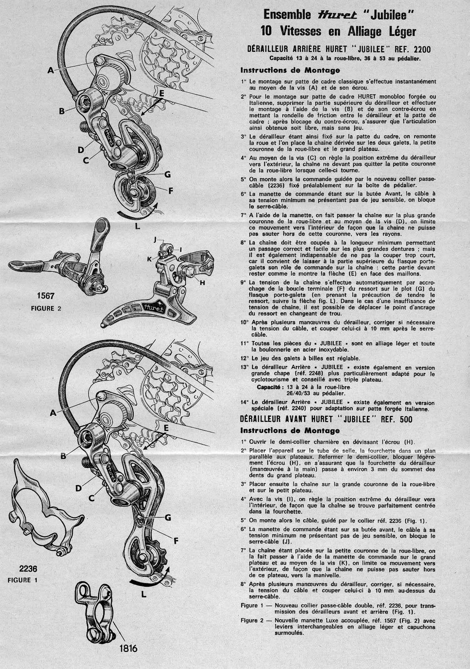
Ensemble Huret "Jubilee" 10 Vitesses en Alliage Léger DÉRAILLEUR ARRIÈRE HURET "JUBILEE" REF. 2200 Capacité 13 à 24 à la roue-libre, 36 à 53 au pédalier. Instructions de Montage 1° Le montage sur patte de cadre classique s'effectue instantanément au moyen de la vis (A) et de son écrou. 2° Pour le montage sur patte …
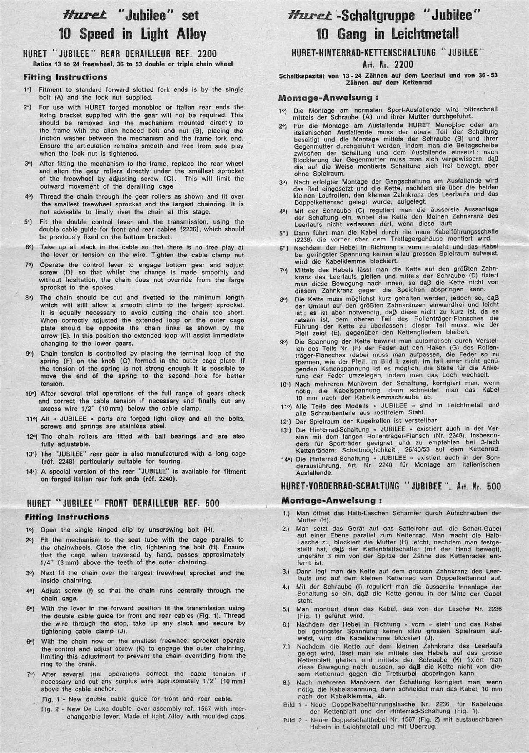
Huret’s fitting instructions for the Jubilee rear derailleur, Ref. 2200, and front derailleur, Ref. 500, printed on the two sides of one sheet. It prints no date.
— Page 1 —
Ensemble Huret “Jubilee”
10 Vitesses en Alliage Léger
DÉRAILLEUR ARRIÈRE HURET “JUBILEE” REF. 2200
Capacité 13 à 24 à la roue-libre, 36 à 53 au pédalier.
Instructions de Montage
1° Le montage sur patte de cadre classique s’effectue instantanément au moyen de la vis (A) et de son écrou.
2° Pour le montage sur patte de cadre HURET monobloc forgée ou Italienne, supprimer la partie supérieure du dérailleur et effectuer le montage à l’aide de la vis (B) et de son contre-écrou en mettant la rondelle de friction entre le dérailleur et la patte de cadre : après blocage du contre-écrou, s’assurer qùe l’articulation ainsi obtenue soit libre, mais sans jeu.
3° Le dérailleur étant ainsi fixé sur la patte du cadre, on remonte la roue et l’on place la chaîne dérivée sur les deux galets, la petite couronne de la roue-libre et le grand plateau.
4° Au moyen de la vis (C) on règle la position extrême du dérailleur vers l’extérieur, la chaîne ne devant pas quitter la petite couronne de la roue-libre lorsque celle-ci tourne.
5° On monte alors la commande guidée par le nouveau collier passe-câble (2236) fixé préalablement sur la boîte de pédalier.
6° La manette de commande étant sur la butée Avant, le câble à sa tension minimum ne présentant pas de jeu sensible, on bloque le serre-câble.
7° A l’aide de la manette, on fait passer la chaîne sur la plus grande couronne de la roue-libre et au moyen de la vis (D), on limite ce mouvement vers l’intérieur de façon que la chaîne ne puisse pas sauter hors de cette couronne, vers les rayons.
8° La chaîne doit être coupée à la longueur minimum permettant un passage correct et facile sur les plus grandes dentures ; mais il est également indispensable de ne pas la couper trop court, car il convient de laisser à la partie supérieure du flasque porte-galets son rôle de commande sur la chaîne : cette partie devant rester comme le montre la flèche (E) en face des maillons.
9° La tension de la chaîne s’effectue automatiquement par accrochage de la boucle terminale (F) du ressort sur le plot (G) du flasque porte-galets (en prenant la précaution de tendre le ressort, suivre la flèche fig. L). Dans le cas d’une insuffisance de tension de chaîne, il est possible de déplacer le point d’ancrage du ressort en changeant de trou.
10° Après plusieurs manœuvres du dérailleur, corriger si nécessaire la tension du câble, et couper celui-ci à 10 mm après le serre-câble.
11° Toutes les pièces du « JUBILEE » sont en alliage léger et toute la boulonnerie en acier inoxydable.
12° Le jeu des galets à billes est réglable.
13° Le dérailleur Arrière « JUBILEE » existe également en version grande chape (réf. 2248) plus particulièrement adapté pour le cyclotourisme et conseillé avec triple plateau.
Capacité : 13 à 24 à la roue-libre
26/40/53 au pédalier.
14° Le dérailleur Arrière « JUBILEE » existe également en version spéciale (réf. 2240) pour adaptation sur patte forgée Italienne.
Callouts: A E B D C G F L
DÉRAILLEUR AVANT HURET “JUBILEE” REF. 500
Instructions de Montage
1° Ouvrir le demi-collier charnière en dévissant l’écrou (H).
2° Placer l’appareil sur le tube de selle, la fourchette dans un plan parallèle aux plateaux. Refermer le demi-collier, bloquer légèrement l’écrou (H), en s’assurant que la fourchette du dérailleur (manœuvrée à la main) passe à environ 3 mm du sommet des dents du grand plateau.
3° Placer ensuite la chaîne sur la grande couronne de la roue-libre et sur le petit plateau.
4° Avec la vis (I), on règle la position extrême du dérailleur vers l’intérieur, de façon que la chaîne se trouve parfaitement centrée dans la fourchette.
5° On monte alors le câble, guidé par le collier réf. 2236 (Fig. 1).
6° La manette de commande étant sur sa butée avant, le câble à sa tension minimum ne présentant pas de jeu sensible, on bloque le serre-câble (J).
7° La chaîne étant placée sur la petite couronne de la roue-libre, on la fait passer à l’aide de la manette de commande sur le grand plateau et au moyen de la vis (K), on limite ce mouvement vers l’extérieur, de façon que la chaîne ne puisse pas sauter hors de ce plateau, vers la manivelle.
8° Après plusieurs manœuvres du dérailleur, corriger, si nécessaire, la tension du câble et couper celui-ci à 10 mm au-dessus du serre-câble.
Callouts: J I K H
Figure 1 — Nouveau collier passe-câble double, réf. 2236, pour transmission des dérailleurs avant et arrière (Fig. 1).
Figure 2 — Nouvelle manette Luxe accouplée, réf. 1567 (Fig. 2) avec leviers interchangeables en alliage léger et capuchons surmoulés.
1567
FIGURE 2
2236
FIGURE 1
Callouts: 1816
[The French side of Huret’s fitting instructions for the “Jubilee” 10-speed set in light alloy, with numbered instructions for the 2200 rear derailleur and the 500 front derailleur beside drawings of the parts. The left column shows two lettered drawings of the rear derailleur on a freewheel and chain, the double lever 1567 (Figure 2), the front derailleur lettered H to K, the double cable guide collar 2236 (Figure 1) and a clip numbered 1816. The Huret name is drawn on the derailleurs and the front derailleur cage, and two horizontal folds cross the sheet.]
— Page 2 —
Huret “Jubilee” set
10 Speed in Light Alloy
HURET “JUBILEE” REAR DERAILLEUR REF. 2200
Ratios 13 to 24 freewheel, 36 to 53 double or triple chain wheel
Fitting Instructions
1°) Fitment to standard forward slotted fork ends is by the single bolt (A) and the lock nut supplied.
2°) For use with HURET forged monobloc or Italian rear ends the fixing bracket supplied with the gear will not be required. This should be removed and the mechanism mounted directly to the frame with the allen headed bolt and nut (B), placing the friction washer between the mechanism and the frame fork end. Ensure the articulation remains smooth and free from side play when the lock nut is tightened.
3°) After fitting the mechanism to the frame, replace the rear wheel and align the gear rollers directly under the smallest sprocket of the freewheel by adjusting screw (C). This will limit the outward movement of the derailling cage
4°) Thread the chain through the gear rollers as shown and fit over the smallest freewheel sprocket and the largest chainring. It is not advisable to finally rivet the chain at this stage.
5°) Fit the double control lever and the transmission, using the double cable guide for front and rear cables (2236), which should be previously fixed on the bottom bracket.
6°) Take up all slack in the cable so that there is no free play at the lever or tension on the wire. Tighten the cable clamp nut
7°) Operate the control lever to engage bottom gear and adjust screw (D) so that whilst the change is made smoothly and without hesitation, the chain does not override from the large sprocket to the spokes.
8°) The chain should be cut and rivetted to the minimum length which will still allow a smooth climb to the largest sprocket. It is equally necessary to avoid cutting the chain too short. When correctly adjusted the extended loop on the outer cage plate should be opposite the chain links as shown by the arrow (E). In this position the extended loop will assist immediate changing to the lower gears.
9°) Chain tension is controlled by placing the terminal loop of the spring (F) on the knob (G) formed in the outer cage plate. If the tension of the spring is not strong enough it is possible to move the end of the spring to the second hole for better tension.
10°) After several trial operations of the full range of gears check and correct the cable tension if necessary and finally cut any excess wire 1/2″ (10 mm) below the cable clamp.
11°) All « JUBILEE » parts are forged light alloy and all the bolts, screws and springs are stainless steel.
12°) The chain rollers are fitted with ball bearings and are also fully adjustable.
13°) The “JUBILEE” rear gear is also manufactured with a long cage (réf. 2248) particularly suitable for touring.
14°) A special version of the rear “JUBILEE” is available for fitment on forged Italian rear fork ends (réf. 2240).
HURET “JUBILEE” FRONT DERAILLEUR REF. 500
Fitting Instructions
1°) Open the single hinged clip by unscrewing bolt (H).
2°) Fit the mechanism to the seat tube with the cage parallel to the chainwheels. Close the clip, tightening the bolt (H). Ensure that the cage, when traversed by hand, passes approximately 1/4″ (3 mm) above the teeth of the outer chainring.
3°) Next fit the chain over the largest freewheel sprocket and the inside chainring.
4°) Adjust screw (I) so that the chain runs centrally through the chain cage.
5°) With the lever in the forward position fit the transmission using the double cable guide for front and rear cables (Fig. 1). Thread the wire through the stop, take up any slack and secure by tightening cable clamp (J).
6°) With the chain now on the smallest freewheel sprocket operate the control and adjust screw (K) to engage the outer chainring, limiting this adjustment to prevent the chain overriding from the ring to the crank.
7°) After several trial operations correct the cable tension if necessary and cut any surplus wire apprixomately 1/2″ (10 mm) above the cable anchor.
Fig. 1 – New double cable guide for front and rear cable.
Fig. 2 – New De Luxe double lever assembly ref. 1567 with interchangeable lever. Made of light Alloy with moulded caps.
Huret -Schaltgruppe “Jubilee”
10 Gang in Leichtmetall
HURET-HINTERRAD-KETTENSCHALTUNG “JUBILEE”
Art. Nr. 2200
Schaltkapazität von 13 – 24 Zähnen auf dem Leerlauf und von 36 – 53 Zähnen auf dem Kettenrad
Montage-Anweisung :
1°) Die Montage am normalen Sport-Ausfallende wird blitzschnell mittels der Schraube (A) und ihrer Mutter durchgeführt.
2°) Für die Montage am Ausfallende HURET Monobloc oder am italienischen Ausfallende muss der obere Teil der Schaltung beseitigt und die Montage mittels der Schraube (B) und ihrer Gegenmutter durchgeführt werden, indem man die Beilagscheibe zwischen der Schaltung und dem Ausfallende einsetzt : nach Blockierung der Gegenmutter muss man sich vergewissern, daß die auf die Weise montierte Schaltung sich frei bewegt, aber ohne Spielraum.
3°) Nach erfolgter Montage der Gangschaltung am Ausfallende wird das Rad eingesetzt und die Kette, nachdem sie über die beiden kleinen Laufrollen, den kleinen Zahnkranz des Leerlaufs und das Doppelkettenrad gelegt wurde, aufgelegt.
4°) Mit der Schraube (C) reguliert man die äusserste Aussenlage der Schaltung ein, wobei die Kette den kleinen Zahnkranz des Leerlaufs nicht verlassen darf, wenn diese läuft.
5°) Dann führt man die Kabel durch die neue Kabelführungsschelle (2236) die vorher ober [?] dem Tretlagergehäuse montiert wird.
6°) Nachdem der Hebel in Richtung « vorn » steht und das Kabel bei geringster Spannung keinen allzu grossen Spielraum aufweist, wird die Kabelklemme blockiert.
7°) Mittels des Hebels lässt man die Kette auf den größten Zahnkranz des Leerlaufs gleiten und mittels der Schraube (D) fixiert man diese Bewegung nach innen, so daß die Kette nicht von diesem Zahnkranz gegen die Speichen abspringen kann.
8°) Die Kette muss möglichst kurz gehalten werden, jedoch so, daß der Umlauf auf den größten Zahnkränzen einwandfrei und leicht ist ; es ist aber notwendig, daß diese nicht zu kurz ist, da es ratsam ist, dem oberen Teil des Rollenträger-Flansches die Führung der Kette zu überlassen : dieser Teil muss, wie der Pfeil zeigt (E), gegenüber den Kettengliedern bleiben.
9°) Die Spannung der Kette bewirkt man automatisch durch Verstellen des Teils Nr. (F) der Feder auf den Haken (G) des Rollenträger-Flansches (dabei muss man aufpassen, die Feder so zu spannen, wie der Pfeil, im Bild L zeigt. Im fall einer nicht genügenden Kettenspannung ist es möglich, die Stelle für die Ankerung der Feder umzelegen, indem man das Loch wechselt.
10°) Nach mehreren Manövern der Schaltung, korrigiert man, wenn nötig, die Kabelspannung, dann schneidet man das Kabel 10 mm nach der Kabelklemmschraube ab.
11°) Alle Teile des Modells « JUBILEE » sind in Leichtmetall und alle Schraubenteile aus rostfreiem Stahl.
12°) Der Spielraum der Kugelrollen ist verstellbar.
13°) Die Hinterrad-Schaltung « JUBILEE » existiert auch in der Version mit dem langen Rollenträger-Flansch (Nr. 2248), insbesonders für Sporträder geeignet und zu empfehlen bei 3-fach Kettenrädern: Schaltmöglichkeit : 26/40/53 auf dem Kettenrad.
14°) Die Hinterrad-Schaltung « JUBILEE » existiert auch in der Sonderausführung, Art. Nr. 2240, für Montage am italienischen Ausfallende.
HURET-VORDERRAD-SCHALTUNG “JUBIBEE”, Art. Nr. 500
Montage-Anweisung :
1.) Man öffnet das Halb-Laschen Scharnier durch Aufschrauben der Mutter (H).
2.) Man setzt das Gerät auf das Sattelrohr auf, die Schalt-Gabel auf einer Ebene parallel zum Kettenrad. Man macht die Halb-Lasche zu, blockiert die Mutter (H) leicht, nachdem man festgestellt hat, daß der Kettenblattschalter (mit der Hand bewegt), ungefähr 3 mm von der Spitze der Zähne des Kettenrades entfernt ist.
3.) Dann legt man die Kette auf dem grossen Zahnkranz des Leerlaufs und auf dem kleinen Kettenrad vom Doppelkettenrad auf.
4.) Mit der Schraube (I) reguliert man die äusserste Innenlage der Schaltung so ein, daß die Kette genau in der Mitte der Gabel steht.
5.) Man montiert dann das Kabel, das von der Lasche Nr. 2236 (Fig. 1) geführt wird.
6.) Nachdem der Hebel in Richtung « vorn » steht und das Kabel bei geringster Spannung keinen allzu grossen Spielraum aufweist, wird die Kabelklemme blockiert (J).
7.) Nachdem die Kette auf dem kleinen Zahnkranz des Leerlaufs gelegt wird, lässt man sie mittels des Hebels auf das grosse Kettenblatt gleiten und mittels der Schraube (K) fixiert man diese Bewegung nach aussen, so daß die Kette nicht von diesem Kettenrad gegen die Tretkurbel abspringen kann.
8.) Nach mehreren Manövern der Schaltung korrigiert man, wenn nötig, die Kabelspannung, dann schneidet man das Kabel, 10 mm nach der Kabelklemme, ab.
Bild 1 – Neue Doppelkabelführungslasche Nr. 2236, für Kabelzüge der Kettenblatt und der Hinterrad-Schaltung (Fig. 1).
Bild 2 – Neuer Doppelschalthebel Nr. 1567 (Fig. 2) mit austauschbaren Hebeln in Leichtmetall und mit Uberzug.
[The English and German side of Huret’s fitting instructions for the “Jubilee” 10-speed set in light alloy, with numbered instructions for the 2200 rear derailleur and the 500 front derailleur in each language. The English text runs down the left column and the German down the right; this side has no drawings, and its notes on Figures 1 and 2 refer to the drawings on the French side. Two horizontal folds cross the sheet.]
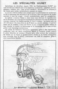 Les Spécialités Huret, the Louison Bobet Derailleur — L’Officiel du cycle, 30 March 1957
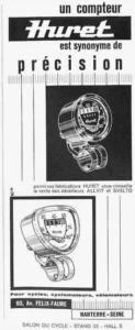 Huret 1964 Advertisement — A Huret Speedometer Means Precision
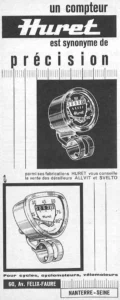 Huret January 1964 Advertisement — A Huret Speedometer Means Precision
 Huret 1966 Advertisement — After the Svelto and Allvit, the Luxe
 Huret 1966 Advertisement — Speedometers for Cycles and Mopeds
Ebykr presents this material for research and education. If you hold rights to it or notice an ownership issue, please contact us and we will respond promptly.
The Ebykr Digest
New articles, timelines, catalog finds and registry activity — assembled from the archive once a month. Your address is never shared.
Double opt-in. One email per month. Unsubscribe at any time with one click.