About Ebykr
Ebykr celebrates classic and vintage lightweight bicycles through provocative imagery and opinion. Ride along with us.
About Ebykr
Ebykr celebrates classic and vintage lightweight bicycles through provocative imagery and opinion. Ride along with us.

Source: Le Cycle, n° 43, January 1964, pages 12, 13, 14, 19, 20, 21, 22, 23, 24, 25, 26, 27; scan of the issue from Cycle Memory (Mémoire du Cycle), Collection privée H.D.
| Type | Review |
|---|---|
| Year | 1964 |
| Publisher | Le Cycle |
| Artist | Daniel Rebour |
| Country | France |
| Language | French |
| Pages | 12 |
| Source | Le Cycle, n° 43, January 1964, pages 12, 13, 14, 19, 20, 21, 22, 23, 24, 25, 26, 27; scan of the issue from Cycle Memory (Mémoire du Cycle), Collection privée H.D. |
| Credit | Ebykr archive |
| Identifier | Permalink https://cyclememory.org/fr/search-coll-list.php?collectionID=773&docID=B-1-0000000809 |
| Transcription | Headings and specifications transcribed; article text summarized |
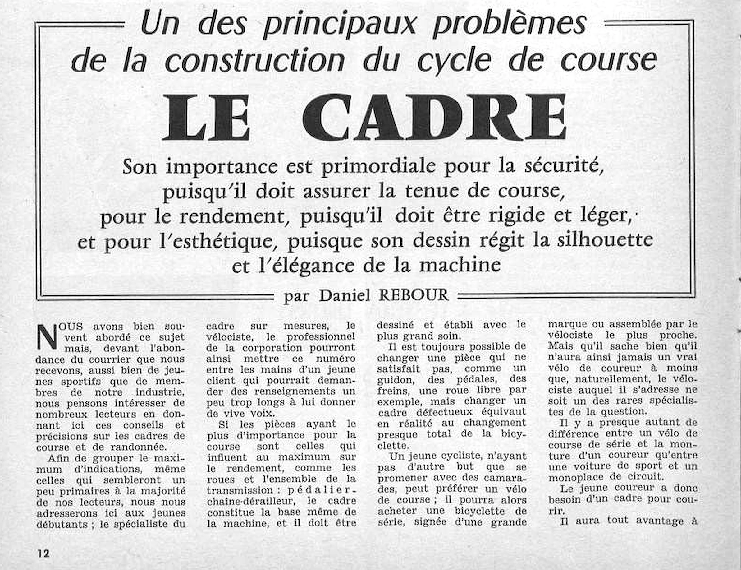
Un des principaux problèmes de la construction du cycle de course LE CADRE Son importance est primordiale pour la sécurité, puisqu'il doit assurer la tenue de course, pour le rendement, puisqu'il doit être rigide et léger, et pour l'esthétique, puisque son dessin régit la silhouette et l'élégance de la machine par Daniel REBOUR 12 LE …
This is a magazine article, so its running text is summarized here rather than reproduced; the headline, byline, specifications and scores are transcribed as printed.
Daniel Rebour’s long article on the racing frame, “Un des principaux problèmes de la construction du cycle de course : le cadre”, ran on 12 pages of Le Cycle n° 43, January 1964 (pages 12 to 14 and 19 to 27). He explains how to size and draw a frame, with the dimensioned frames of Baldini, Jacques Anquetil and Nencini and a Peugeot racing plan, then fork ends, lugs, brazed-on fittings, checking a new frame, enameling and bearings, and the randonneur’s frame, with his pen drawings. The title, headings, dimensions and folios are transcribed as printed; the text and captions are summarized in Ebykr’s words, and the page images carry the article in full.
— Page 1 —
Un des principaux problèmes de la construction du cycle de course
LE CADRE
Son importance est primordiale pour la sécurité, puisqu’il doit assurer la tenue de course, pour le rendement, puisqu’il doit être rigide et léger, et pour l’esthétique, puisque son dessin régit la silhouette et l’élégance de la machine
par Daniel REBOUR
[Ebykr summary; the article’s text is not reproduced. The title frame states the theme: the frame is one of the main problems in building a racing bicycle, and it matters for safety (it must give sure road holding), for efficiency (it must be stiff and light) and for looks (its design sets the silhouette and elegance of the machine). Rebour opens by saying the magazine has often treated the subject, but the volume of mail from young riders and from members of the cycle industry leads it to set out advice and details on racing and touring (randonnée) frames. To gather as much guidance as possible, including points most readers will find elementary, he addresses young beginners, so that the made-to-measure frame specialist, the vélociste (cycle dealer) and other professionals of the trade can hand this issue to a young customer whose questions would take too long to answer in person. Wheels and the transmission (chainset, chain and derailleur) are the parts that most affect efficiency, but the frame is the very base of the machine and must be drawn and built with the greatest care: a handlebar, pedals, brakes or a freewheel can be swapped, while replacing a faulty frame means replacing almost the whole bicycle. A young cyclist who only wants to ride with friends may choose a racing-style bicycle and can buy a series-built machine bearing a large brand name or one assembled by the nearest dealer, but he will never own a true racing bicycle unless that dealer is one of the rare specialists. Rebour compares the gap between a series-built racing bicycle and a racer’s mount to the gap between a sports car and a single-seat circuit racing car. The young racer therefore needs a proper frame to race, and the sentence that follows runs on to the next page.]
[This part of the page carries no drawings or photographs: the title, subtitle and byline are set in a double-ruled frame across the full width, above four columns of text with a drop capital N.]
12
[The top of printed page 12, above the title frame, carries the end of the column Nouvelles de Belgique, which is not part of this article and is not transcribed here.]
— Page 2 —
LE PROBLÈME DU CADRE — LE PROBLÈME DU CADRE
COMMENT DESSINER UN CADRE
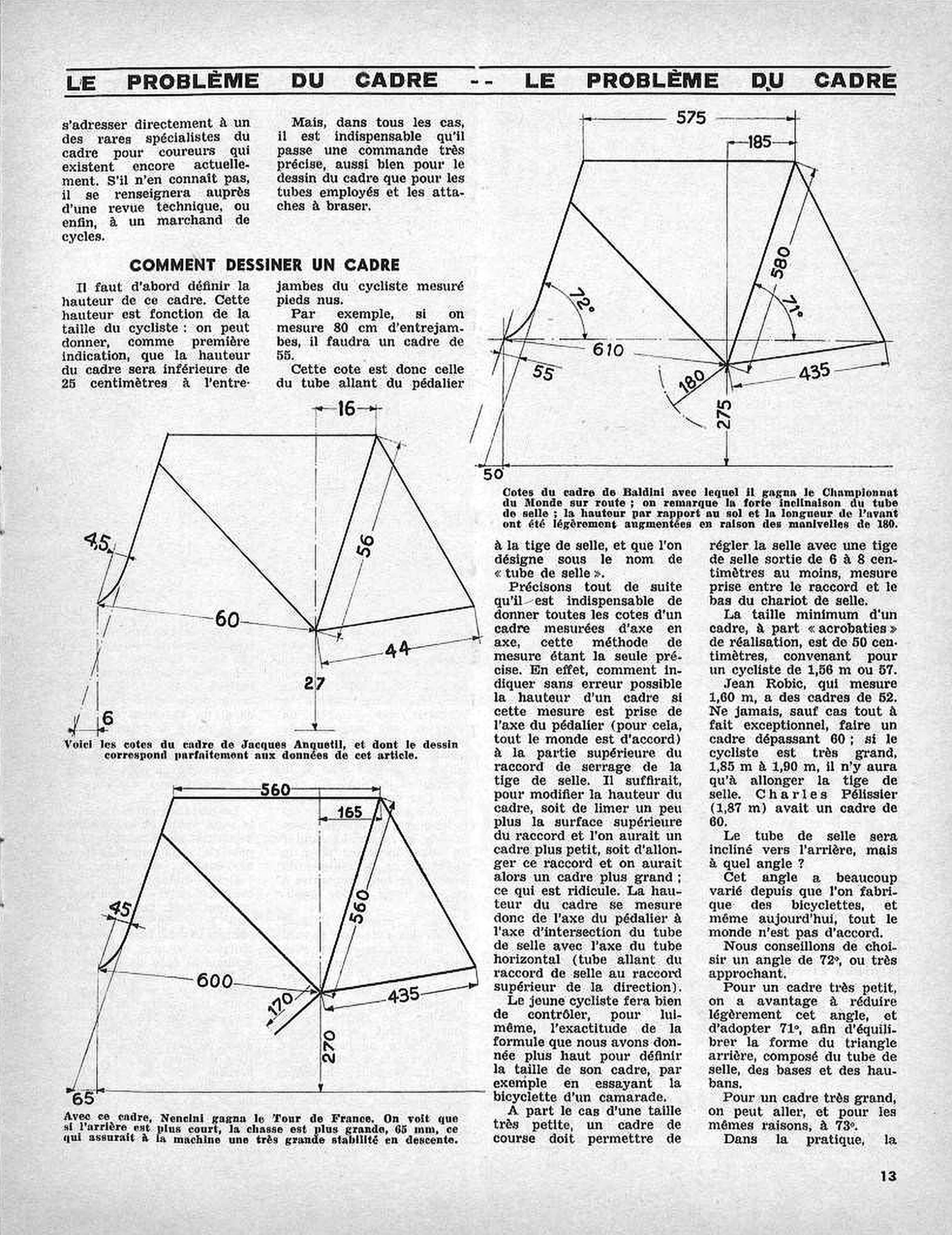
[Dimensions printed on the drawing at the upper right of the page, the frame of Baldini (millimeters):]
575 [top tube, across the top]
185 [horizontal setback of the seat-tube top behind the vertical through the bottom bracket]
580 [seat tube, along the tube from the bottom-bracket axis]
72° [head angle, to the horizontal through the wheel axles]
71° [seat angle, to the same horizontal]
610 [front axle to bottom-bracket axis]
55 [fork rake]
180 [crank length, with the pedal circle drawn as a dash-dot arc]
435 [chainstay, bottom-bracket axis to rear axle]
275 [bottom-bracket height above the ground]
50 [trail, at ground level]
[Dimensions printed on the drawing at the middle left, the frame of Jacques Anquetil (centimeters; no angle is printed):]
16 [horizontal setback of the seat-tube top]
4,5 [fork rake]
56 [seat tube]
60 [front axle to bottom-bracket axis]
44 [chainstay]
27 [bottom-bracket height]
6 [trail, at ground level]
[Dimensions printed on the drawing at the lower left, the frame of Nencini (millimeters; no angle is printed):]
560 [top tube, across the top]
165 [horizontal setback of the seat-tube top]
560 [seat tube]
45 [fork rake]
600 [front axle to bottom-bracket axis]
170 [crank length]
435 [chainstay]
270 [bottom-bracket height]
65 [trail, at ground level]
[Ebykr summary; the article’s text is not reproduced. Continued from page 12: the young racer does best to go straight to one of the rare frame specialists for racing riders still working, and if he knows none he can ask a technical review or a cycle dealer; in every case he must place a very precise order, covering the frame drawing, the tubes and the fittings to be brazed on. Under COMMENT DESSINER UN CADRE, Rebour starts with frame height, which depends on the rider: as a first guide it is 25 centimeters less than the inside-leg length measured barefoot, so an 80 cm inseam calls for a frame of 55. That figure is the length of the seat tube (tube de selle), from the bottom bracket to the seat post. Every frame dimension must be given center to center, the only precise method: measuring to the top of the seat-post clamp lug would let the size change by filing or lengthening the lug. Frame height therefore runs from the bottom-bracket axis to the meeting of the seat-tube and top-tube axes. The rider should check the formula himself, for instance on a friend’s bicycle. Except for very small sizes, a racing frame should leave at least 6 to 8 centimeters of seat post showing between the lug and the saddle clamp (chariot de selle). The smallest sensible frame is 50 centimeters, for a rider of 1.56 m or 1.57 m; Jean Robic, 1.60 m tall, rides frames of 52. A frame over 60 should be built only in very exceptional cases, a rider of 1.85 m to 1.90 m simply raising the seat post; Charles Pélissier (1.87 m) had a frame of 60. On seat-tube angle, which has varied since bicycles were first built and still divides opinion, Rebour advises 72° or close to it, 71° for a very small frame to balance the rear triangle (seat tube, chainstays and seat stays) and up to 73° for a very large one. The next sentence continues on page 14. The captions: the top drawing gives the dimensions of the frame on which Baldini won the world road championship (Championnat du Monde sur route), noting its strongly sloped seat tube and a bottom-bracket height and front length raised slightly for 180 mm cranks; the middle drawing gives the dimensions of Jacques Anquetil’s frame, which match the figures in this article exactly; the bottom drawing shows the frame on which Nencini won the Tour de France, its rear shorter but its trail larger, 65 mm, giving the machine great stability downhill.]
[Three dimensioned line drawings of racing frames in side view, front to the left, each showing the head tube with the curve of the fork blade, the top tube, down tube, seat tube, chainstay and seat stay, a vertical dash-dot line through the bottom bracket, the ground line and dimension arrows: the frame of Baldini at the upper right, with a horizontal dash-dot line through the axles and the two angles drawn as arcs; the frame of Jacques Anquetil at the middle left; the frame of Nencini at the lower left. None of the three drawings carries a Rebour signature.]
13
— Page 3 —
LE PROBLÈME DU CADRE — LE PROBLÈME DU CADRE
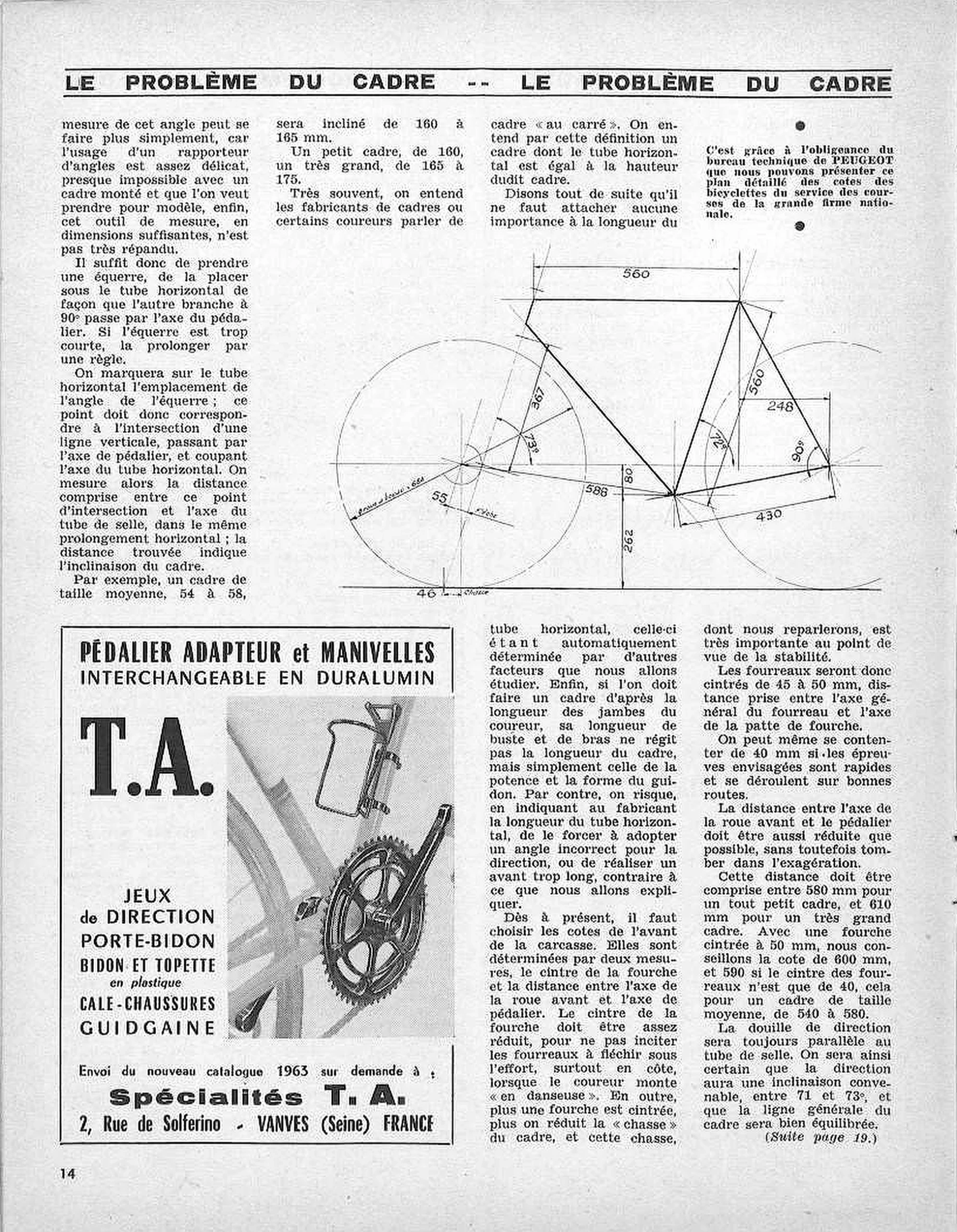
[Dimensions and labels printed on the frame drawing at the upper right of the page (millimeters):]
560 [top tube, horizontal, across the top]
560 [seat tube, along the tube]
248 [horizontal, from the vertical through the top of the seat tube to the rear axle]
367 [measured parallel to the steering axis, from the bottom of the head tube]
73° [head angle]
72° [seat angle]
90° [angle marked at the rear axle]
588 [front axle to bottom-bracket axis]
80 [drop of the bottom-bracket axis below the line of the wheel axles]
262 [bottom-bracket height above the ground]
430 [chainstay]
55 [fork rake, with the label below]
Flèche [?]
46 [trail, at ground level, with the label below]
Chasse
Ø roue [illegible] boyau = 684 [?] [the front wheel’s diameter, written along a radius]
(Suite page 19.)
[Ebykr summary; the article’s text is not reproduced. Continued from page 13: there is a simpler way to measure the seat-tube angle, since a protractor is awkward to use, nearly impossible on a built-up frame one wants to copy, and rarely found in a large enough size. Rebour sets a carpenter’s square (équerre) under the top tube with its other arm passing through the bottom-bracket axle, extended with a rule if needed, and marks the corner on the top tube: the horizontal distance from that mark to the seat-tube axis expresses the frame’s slope. A medium frame of 54 to 58 is inclined 160 to 165 mm, a small frame 160 and a very large one 165 to 175. Builders and some riders speak of a frame “au carré”, one whose top tube equals its height, but Rebour says the top-tube length deserves no attention, because other factors fix it automatically: a frame is built to the rider’s legs, while torso and arm length govern only the stem and the shape of the handlebar, and dictating the top tube to the maker risks forcing a wrong head angle or too long a front end. He then sets the front of the frame by two measures, the fork rake (cintre de la fourche) and the distance from the front axle to the bottom-bracket axle. The rake should be modest so that the fork blades (fourreaux) do not flex under effort, above all when climbing out of the saddle (“en danseuse”), and because more rake means less trail (chasse), which matters greatly for stability: 45 to 50 mm, measured from the blade’s general axis to the axle of the fork end (patte de fourche), or even 40 mm for fast races on good roads. The front axle to bottom-bracket distance should be as short as is sensible, 580 mm for a very small frame to 610 mm for a very large one; for a medium frame of 540 to 580 he advises 600 mm with 50 mm of rake and 590 with 40. The head tube (douille de direction) should always run parallel to the seat tube, giving a steering angle between 71 and 73° and a balanced frame line. The text continues on page 19. The note at the upper right, set between two bullets, explains that the detailed dimension plan of the racing-department bicycles of the great national firm is published by courtesy of the technical office (bureau technique) of PEUGEOT.]
[One dimensioned technical drawing of a racing bicycle in side view, front to the left, across the upper right of the page: the frame in heavy line, the steering axis and construction lines in light line, both wheels drawn as broken circles, with dimension arrows, angle arcs and small hand-lettered labels. The page carries no Rebour signature.]
14
[The lower left of the page carries an advertisement for Spécialités T.A., held as its own record.]
— Page 4 —
LE PROBLÈME DU CADRE — LE PROBLÈME DU CADRE
(Suite de la page 14.)
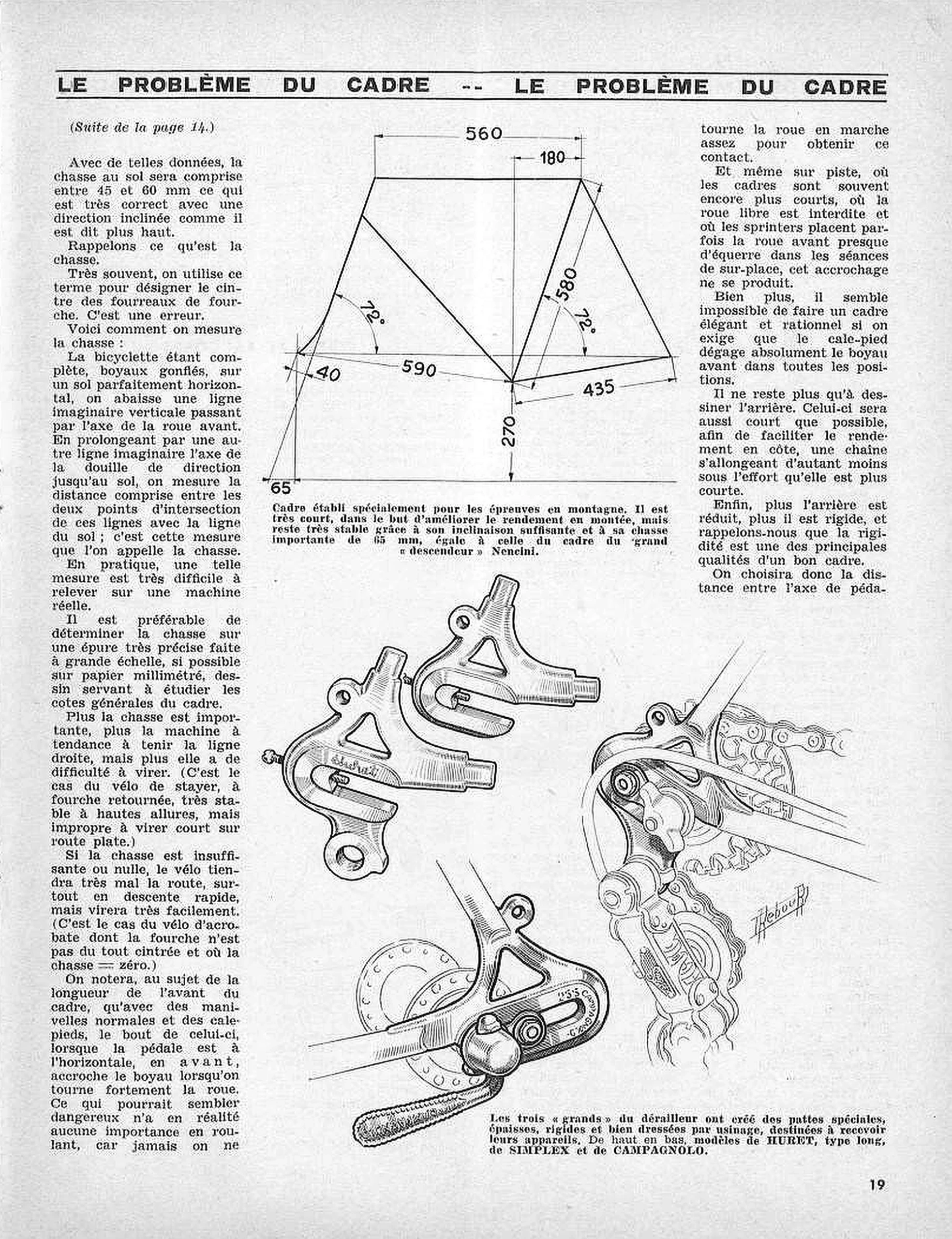
[Dimensions printed on the frame drawing at the top center of the page (millimeters):]
560 [top tube, across the top]
180 [horizontal setback of the seat-tube top behind the vertical through the bottom bracket]
580 [seat tube, along the tube]
72° [head angle, to the horizontal through the wheel axles]
72° [seat angle, to the same horizontal]
40 [fork rake]
590 [front axle to bottom-bracket axis]
435 [chainstay]
270 [bottom-bracket height above the ground]
65 [trail, at ground level]
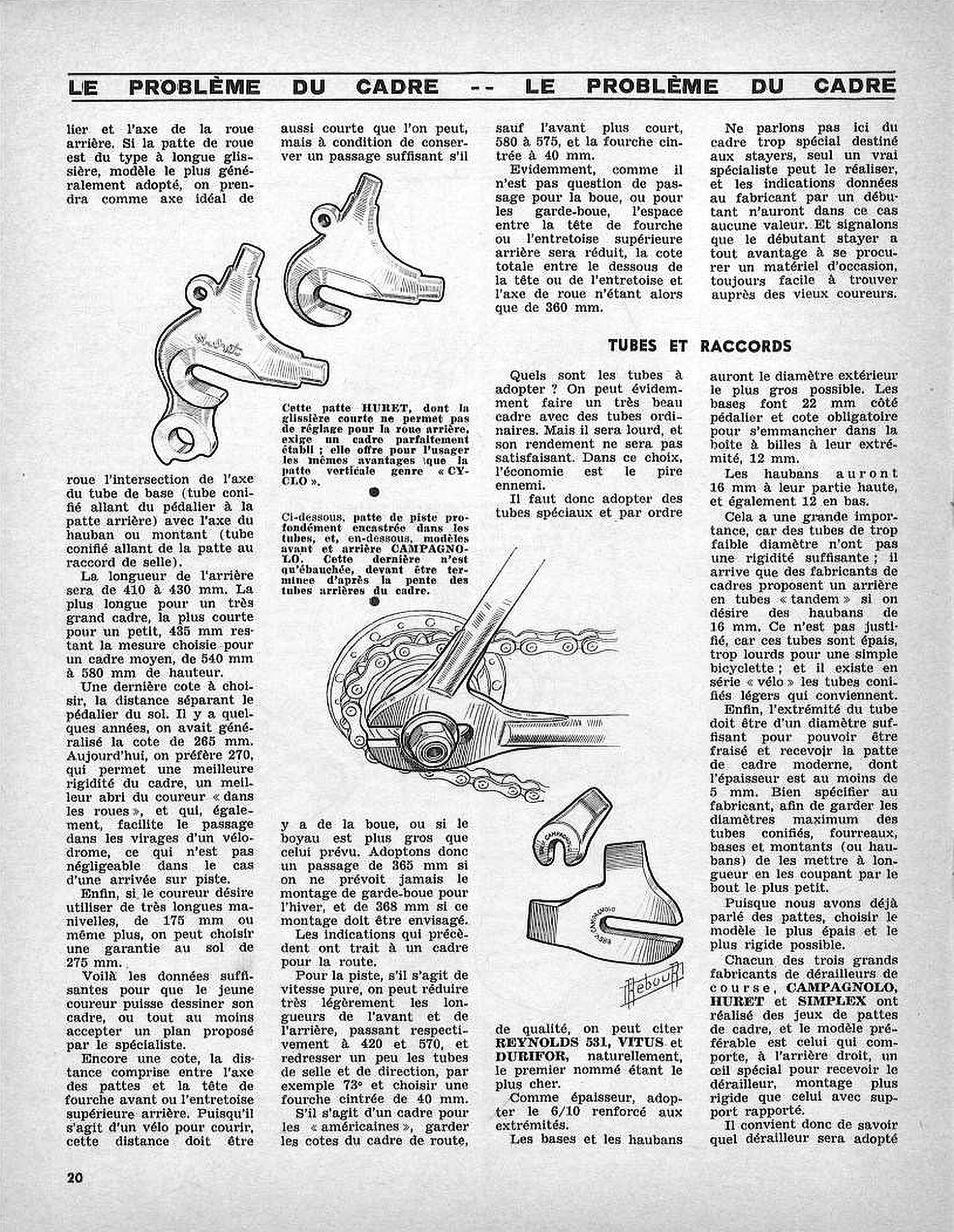
[Ebykr summary; the article’s text is not reproduced. Continued from page 14: with the figures given so far, the trail at the ground falls between 45 and 60 mm, which Rebour judges correct for the steering angle already advised. He then defines trail (chasse), a word often misused for the rake of the fork blades. With the bicycle complete, its tubulars inflated and standing on level ground, one drops a vertical through the front axle and extends the axis of the head tube (douille de direction) to the ground: the distance between the two points where these lines meet the ground is the trail. Because this is very hard to measure on a real machine, he recommends finding it on a precise large-scale layout (épure), ideally on millimeter paper, the same drawing used to study the frame’s general dimensions. More trail makes a bicycle hold a straight line but turn less readily, as with the stayer’s bicycle and its reversed fork, very stable at high speed but unable to turn tightly on a flat road; too little or no trail makes it hold the road badly, above all in fast descents, while turning very easily, as with the acrobat’s bicycle, whose straight fork has a trail of zero. On front-end length, he notes that with normal cranks and toe clips the tip of the clip, with the pedal forward and level, touches the front tubular when the wheel is turned hard; this looks dangerous but does not matter when riding, since the wheel is never turned that far on the move, nor even on the track, where frames are often shorter still, freewheels are banned and sprinters set the front wheel almost square during track stands (séances de sur-place). An elegant and rational frame would in fact be impossible if the toe clip had to clear the front tubular in every position. The rear should be as short as possible, for efficiency when climbing (a shorter chain stretches less under effort) and for stiffness, one of the chief qualities of a good frame; the sentence on the bottom bracket to rear axle distance continues on page 20. The caption under the frame drawing describes a frame built specially for mountain races, very short to improve climbing efficiency yet very stable thanks to its sufficient angle and its large 65 mm trail, equal to that of the frame of the great “descendeur” Nencini. The caption under the drawings of fork ends says that the three “grands” of the derailleur have created special rear fork ends (pattes), thick, stiff and accurately machined, to take their mechanisms, and names them from top to bottom as models by HURET (type long), SIMPLEX and CAMPAGNOLO.]
[A dimensioned line drawing of a racing frame in side view, front to the left, at the top center, between the first and last columns, with the ground line, a vertical dash-dot line through the bottom bracket and two angle arcs. Below it, across the lower right of the page, a group of shaded pen drawings of rear fork ends with derailleur hangers: two machined hangers at the upper left, the front one bearing the script name Huret; a fork end at the right shown with a derailleur, chain and freewheel fitted, the derailleur drawn with its tension cage; and at the bottom a fork end lettered CAMPAGNOLO, shown on the chainstay and seat stay with the hub flange and axle nut. The group carries one signature, “Rebour” in script on a slanting stroke, just right of the derailleur drawing, toward the right edge of the page and about three-quarters of the way down. The frame drawing at the top is unsigned.]
19
— Page 5 —
LE PROBLÈME DU CADRE — LE PROBLÈME DU CADRE
TUBES ET RACCORDS
[Ebykr summary; the article’s text is not reproduced. Continued from page 19, on the distance from the bottom-bracket axle to the rear axle: with the long-slot rear fork end (patte à longue glissière), the most generally adopted model, the ideal wheel axis is taken where the axis of the chainstay (tube de base, the tapered tube from the bottom bracket to the rear fork end) meets the axis of the seat stay (hauban or montant, the tapered tube from the fork end to the seat lug). The rear should measure 410 to 430 mm, the longest for a very large frame and the shortest for a small one, while the print gives 435 mm as the figure chosen for a medium frame of 540 mm to 580 mm in height. The last dimension is bottom-bracket height: 265 mm was general a few years ago, but 270 is now preferred for better frame stiffness, better shelter for the rider riding in the wheels and easier passage through the bankings of a velodrome, which matters in a track finish; with very long cranks of 175 mm or more, a ground clearance of 275 mm can be chosen. These figures are enough for the young racer to draw his frame, or at least to accept a plan proposed by the specialist. One more dimension is the distance from the axle of the fork ends to the fork crown (tête de fourche) or the rear upper bridge (entretoise supérieure arrière), as short as possible while leaving room for mud or a fatter tubular: 365 mm if mudguards will never be fitted for winter, 368 mm if they will. All of this concerns a road frame. For pure-speed track racing the front and rear lengths can be cut very slightly (the print gives 420 and 570), the seat and head tubes steepened, for example to 73°, and a fork with 40 mm of rake chosen. A frame for the “américaines” (Madison races) keeps the road dimensions except a shorter front, 580 to 575, and a fork raked 40 mm; with no mud or mudguards to clear, the total from the underside of the crown or bridge to the wheel axle is then only 360 mm. Rebour leaves aside the very special stayer frame, which only a true specialist can build, and advises the beginner stayer to buy secondhand equipment, always easy to find among old riders. Under TUBES ET RACCORDS he warns that ordinary tubes make a heavy frame of poor efficiency, economy being the worst enemy here, and names the special tubes, in order of quality, as REYNOLDS 531, VITUS and DURIFOR, the first being the dearest, in a 6/10 gauge reinforced at the ends. Chainstays (bases) and seat stays (haubans) should have the largest possible outside diameter: chainstays 22 mm at the bottom-bracket end, the size required to fit the bottom-bracket shell (boîte à billes), and 12 mm at their tip; seat stays 16 mm at the top and 12 at the bottom. Tubes of too small a diameter lack stiffness; some frame makers offer a rear in “tandem” tubes to obtain 16 mm stays, which he finds unjustified because those tubes are thick and too heavy, while light tapered tubes exist in the “vélo” series. The tube end must be large enough to be slotted for the modern fork end, at least 5 mm thick, and the maker should be told to keep the maximum diameters of the tapered tubes (fork blades, chainstays and seat stays) by cutting them to length from the small end. He advises the thickest and stiffest fork end: each of the three great makers of racing derailleurs, CAMPAGNOLO, HURET and SIMPLEX, has produced sets of frame fork ends, the best having on the right rear a special eye to take the derailleur, a stiffer mounting than an added bracket, so one must know which derailleur will be fitted (continued on page 21). The first caption says this HURET fork end, whose short slot allows no adjustment of the rear wheel, demands a perfectly built frame and gives the user the same advantages as the vertical “CYCLO” type of fork end. The second caption describes, below it, a track fork end set deep into the tubes and, lower still, front and rear CAMPAGNOLO models, the rear one only roughed out, to be finished to the slope of the frame’s rear tubes.]
[Shaded pen drawings of fork ends across the middle of the page. At the upper left, two Huret rear fork ends with derailleur hangers, the nearer one bearing the script name Huret on its face. In the center, a track fork end with a rearward-facing slot, shown brazed into the chainstay and seat stay with the axle nut, sprocket and chain in place. Below and to its right, two unfinished CAMPAGNOLO fork ends, a front fork end and a rear one, each with the name stamped around the slot. The page carries one signature, “Rebour” in script inside a small slanting box, at the lower right of the CAMPAGNOLO fork ends, about two-thirds of the way across the page and four-fifths of the way down. The Huret drawings are unsigned.]
20
— Page 6 —
LE PROBLÈME DU CADRE — LE PROBLÈME DU CADRE
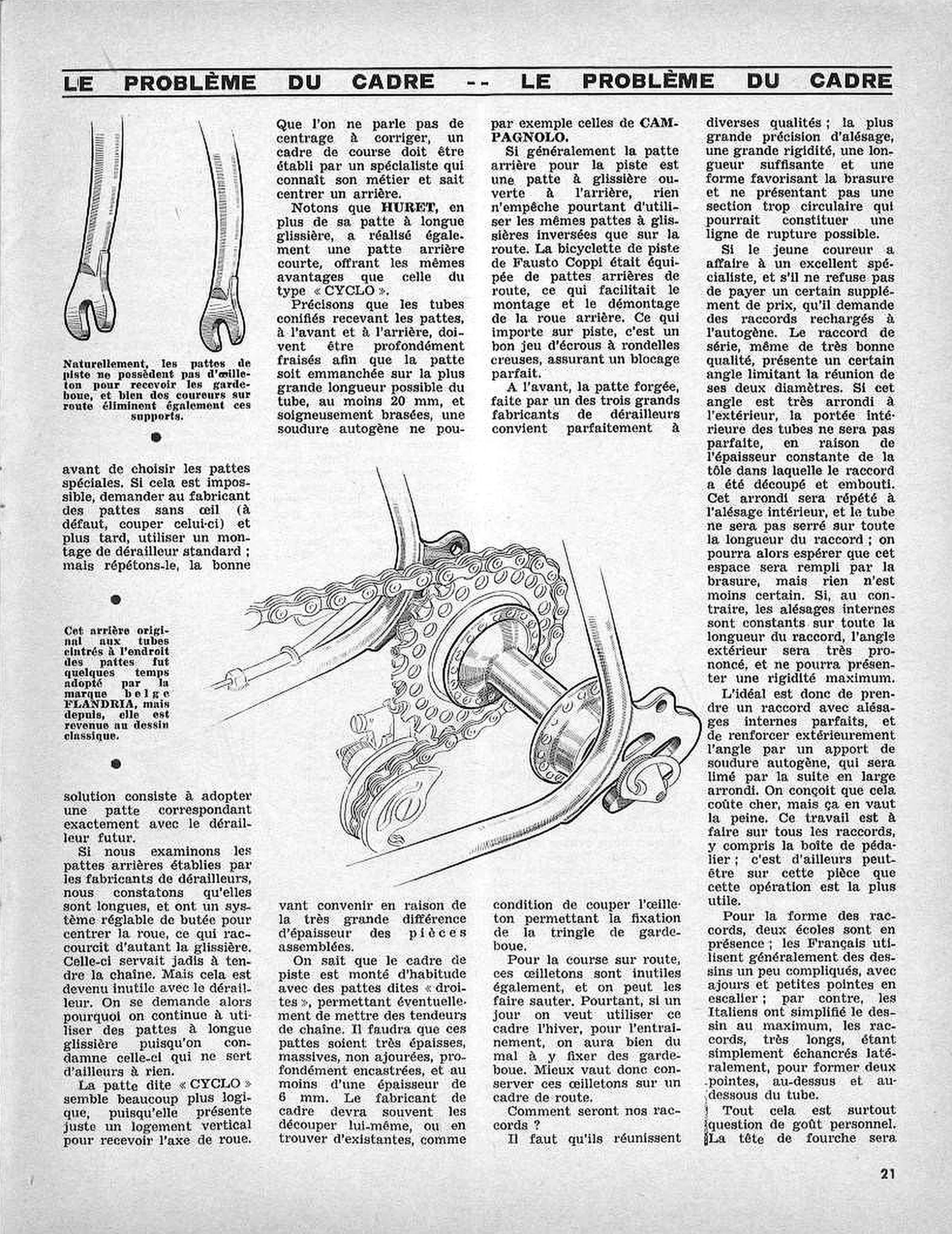
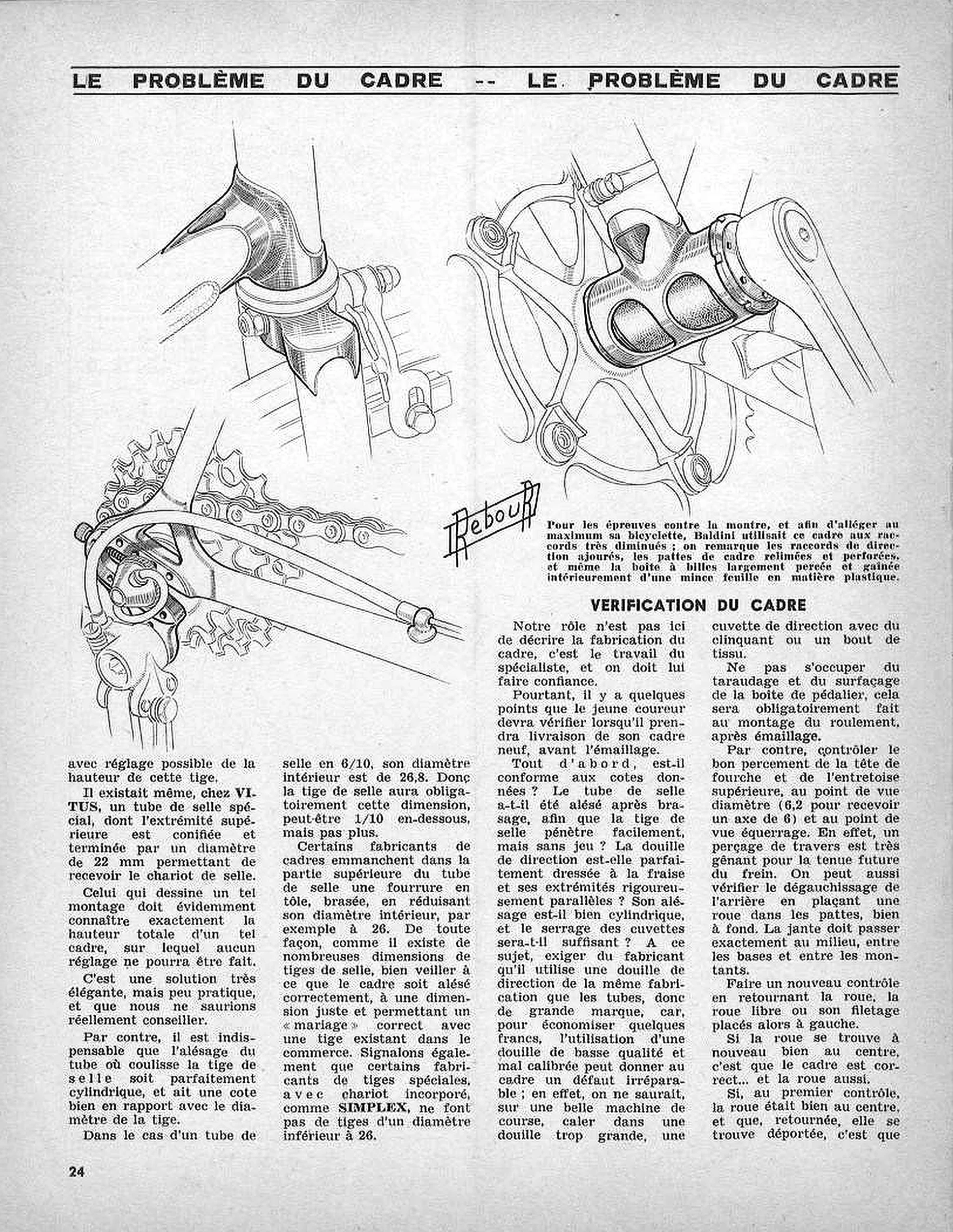
[Ebykr summary; the article’s text is not reproduced. Continued from page 20: the derailleur to be fitted should be known before choosing the special fork ends; if that is impossible, the rider should ask the maker for fork ends without the derailleur eye (or have the eye cut off) and later use a standard derailleur mounting, but Rebour repeats that the right answer is a fork end that matches the future derailleur exactly. The rear fork ends made by the derailleur makers are long and carry an adjustable stop to center the wheel, which shortens the slot accordingly; the slot once served to tension the chain, which the derailleur has made useless, so he asks why long-slot fork ends are still used. The so-called “CYCLO” fork end, with just a vertical slot for the wheel axle, seems far more logical to him: there should be no question of correcting the centering, since a racing frame must be built by a specialist who knows his trade and can center a rear. HURET, besides its long-slot fork end, has also made a short rear fork end with the same advantages as the “CYCLO” type. The tapered tubes that take the fork ends, front and rear, must be deeply slotted so the fork end goes in over the greatest possible length of tube, at least 20 mm, and carefully brazed; autogenous welding cannot suit because the parts joined differ so much in thickness. A track frame is usually built with so-called straight (“droites”) fork ends, which allow chain tensioners; these must be very thick, solid rather than cut out, deeply set in and at least 6 mm thick, and the frame builder will often have to cut them himself or find existing ones, for example those of CAMPAGNOLO. Although the track rear fork end is usually open to the rear, nothing prevents using the same reversed-slot fork ends as on the road: the track bicycle of Fausto Coppi had road rear fork ends, which made fitting and removing the rear wheel easier, and what matters on the track is a good set of nuts with hollow washers that lock perfectly. At the front, the forged fork end made by one of the three great derailleur makers suits perfectly, provided the eyelet for the mudguard stay is cut off; on a road racing frame these eyelets are also useless and can be removed, but since mounting mudguards for winter training becomes very hard without them, Rebour prefers to keep them on a road frame. He then asks what the lugs (raccords) should be. They must combine the greatest boring precision, great stiffness, enough length, a shape that helps the brazing and no too-circular section that could become a line of fracture. A young racer dealing with an excellent specialist who will pay extra should ask for lugs built up by autogenous welding (rechargés à l’autogène): a series lug, even of very good quality, has an angle where its two diameters meet; if it is well rounded outside, the tubes do not seat perfectly inside, because the sheet from which the lug was cut and pressed has a constant thickness, and one can only hope the brazing fills the gap; if the bores are constant over the whole lug, the outside angle is sharp and cannot give maximum stiffness. The ideal is a lug with perfect internal bores, reinforced outside at the angle with autogenous weld metal later filed to a broad radius, costly but worth it, on every lug including the bottom-bracket shell (boîte de pédalier), where it may be most useful. On lug shape there are two schools: the French generally use rather complicated designs with cutouts and small stepped points, while the Italians have simplified the design to the utmost, their very long lugs being simply notched at the sides to form two points, above and below the tube. All this is mainly a matter of personal taste; the sentence on the fork crown (tête de fourche) runs on to the next page. The first caption notes that track fork ends naturally have no eyelet for mudguards, and that many road riders also remove these supports. The second caption says that this original rear, with stays bent where they meet the fork ends, was for some time adopted by the Belgian make FLANDRIA, which has since returned to the classic design.]
[Two kinds of pen drawing. At the upper left, two front fork ends brazed into the tips of fork blades, drawn without mudguard eyelets. Across the middle of the page, a larger drawing of the rear of a frame from behind and to the right: the chainstay and seat stay bent where they meet the rear fork end, the hub with its flanges, the freewheel and chain, a derailleur with its pulley cage below the freewheel and, at the right, the fork end with its eyelet, two slots and a knurled fitting on the axle end. Neither drawing carries a Rebour signature; the page has no signature anywhere.]
21
— Page 7 —
LE PROBLÈME DU CADRE — LE PROBLÈME DU CADRE
ATTACHES A BRASER
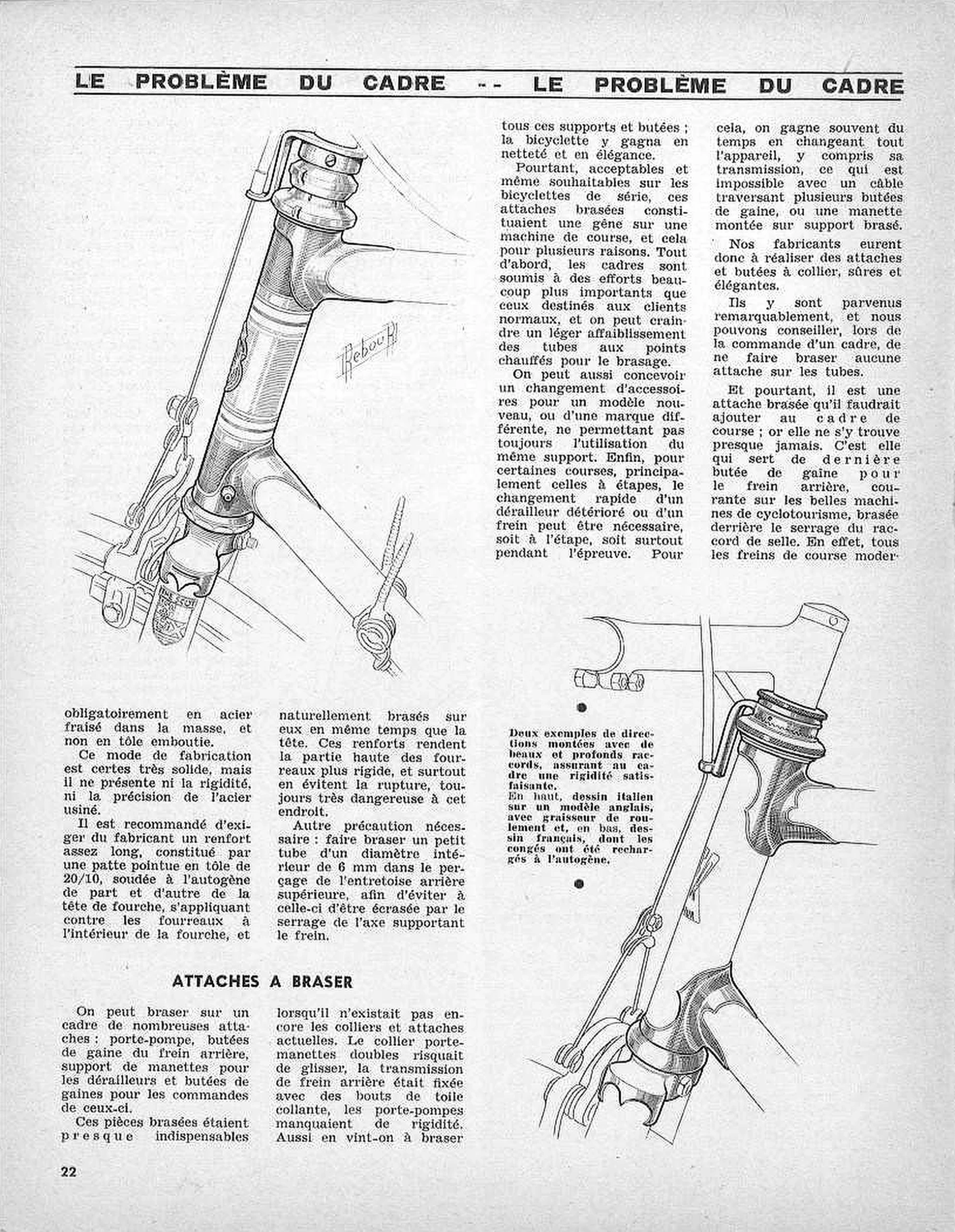
[Ebykr summary; the article’s text is not reproduced. The page opens by finishing the sentence on the fork crown begun at the foot of page 21: the crown must be steel milled from the solid, not pressed from sheet. A pressed crown is certainly very strong but has neither the rigidity nor the precision of machined steel. The author advises asking the builder for a fairly long reinforcement on each side of the fork crown: a pointed tab of 20/10 sheet steel, welded by oxy-acetylene to the crown, lying against the fork blades on the inside of the fork and brazed to them at the same time as the crown. These reinforcements stiffen the top of the blades and above all prevent a break, which is always very dangerous at that point. A further precaution is to have a small tube of 6 mm inside diameter brazed into the hole in the upper rear bridge, so that the bridge is not crushed when the bolt carrying the brake is tightened. Under the heading on brazed-on fittings, the author lists what can be brazed to a frame: pump pegs, rear brake cable stops, lever bosses for the derailleurs and cable stops for their controls. These were almost indispensable before today’s clamps and clip-on fittings existed, when a double lever clamp could slip, the rear brake cable was held with bits of adhesive tape and pump holders lacked rigidity; brazing them on made the bicycle neater and more elegant. Acceptable and even desirable on production bicycles, brazed fittings are a handicap on a racing machine for several reasons: racing frames take far greater stresses than those built for ordinary customers, and the tubes may be slightly weakened where they were heated for brazing; a new model or a different make of accessory may not fit the same boss; and in some races, stage races above all, a damaged derailleur or brake may have to be changed quickly at the end of a stage or during the race itself, which is fastest done by swapping the whole unit with its cable, impossible when the cable runs through several brazed stops or the lever sits on a brazed boss. The makers therefore had to produce safe and elegant clamp-on fittings and stops; they have succeeded remarkably, and the author advises ordering a frame with no fitting brazed to the tubes. One brazed fitting, however, should be added to the racing frame and almost never is: the last cable stop for the rear brake, common on fine touring (cyclotourisme) machines, brazed behind the seat-lug clamp, because all modern racing brakes (the sentence continues on page 23). The caption between the right-hand columns presents two examples of head assemblies built with handsome deep lugs that give the frame satisfactory rigidity: the upper one an Italian design on an English model, with a lubricator for the head bearing, the lower one a French design whose fillets have been built up by oxy-acetylene welding.]
[Two drawings in perspective. The large drawing at upper left shows a racing head tube with long pointed lugs and the start of the top and down tubes, the headset, a lubricator on the lower head lug, a front caliper brake with its cable and cable hanger, the fork crown and the tops of the fork blades (one carrying a shield-shaped transfer) and two cables held to the down tube by a clip. The drawing at lower right shows a second head tube with deeply cut, ornate lugs and filleted joints, a knurled headset, the brake cable hanger, the front brake and a fork crown, beside a piece of handlebar stem and bolts at upper left. The page carries one signed drawing: “Rebour” in script, inside a small slanted box, sits to the right of the head tube in the upper-left drawing, about one third of the way down the page. The lower-right drawing is unsigned.]
22
— Page 8 —
LE PROBLÈME DU CADRE — LE PROBLÈME DU CADRE
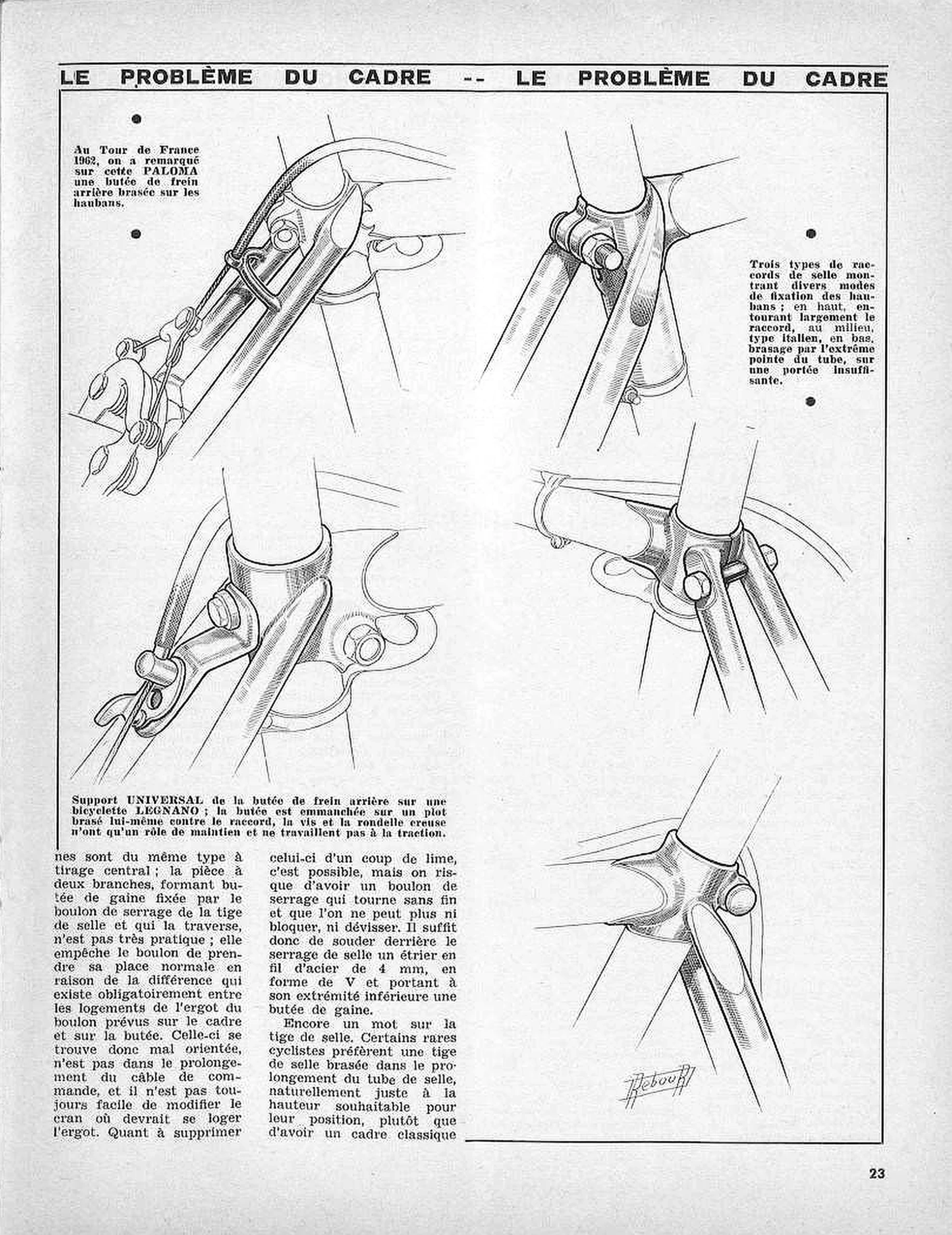
[Ebykr summary; the article’s text is not reproduced. The text finishes the argument from page 22 for a brazed last cable stop for the rear brake. Modern racing brakes are all of the same center-pull type, and the usual two-armed cable stop held by the seat-pin clamp bolt, which passes through it, is not very practical: because the recesses for the bolt’s locating lug on the frame and on the stop never match, the bolt cannot sit in its proper place, the stop ends up badly aligned and out of line with the control cable, and the notch for the lug is not always easy to alter. Filing the lug away is possible but risks a clamp bolt that spins endlessly and can be neither tightened nor undone. The simple answer is to have a V-shaped stirrup of 4 mm steel wire welded behind the seat clamp, carrying a cable stop at its lower end. The author then turns to the seat pin: a few rare riders prefer a seat pin brazed in line with the seat tube, set at exactly the height their position requires, rather than a classic frame (the sentence continues on page 24). The three captions add the following. At the 1962 Tour de France a PALOMA was seen with a rear brake cable stop brazed on the seat stays. A UNIVERSAL support carries the rear brake cable stop on a LEGNANO bicycle: the stop is fitted over a stud that is itself brazed against the lug, and its screw and cupped washer only hold it in place, taking none of the cable’s pull. Three types of seat lug show different ways of joining the seat stays: at the top, stays wrapping widely around the lug; in the middle, the Italian type; at the bottom, stays brazed on by the very tip of the tube, with too small a bearing surface.]
[Five drawings in perspective, set inside a ruled frame. At upper left, the seat cluster of the PALOMA seen from behind, with a loop-shaped cable stop brazed across the seat stays and the cable running down to a center-pull rear brake. At lower left, a seat lug with the UNIVERSAL cable-stop arm bolted to a stud on the lug, the cable housing ending in it, the seat bolt and the tops of the seat stays. Down the right side, three seat lugs one above the other: at the top, stays whose tops wrap broadly around the lug, with the seat bolt; in the middle, the Italian type, with capped stay tops fixed to the sides of the lug and the seat bolt passing between them; at the bottom, a stay brazed to the lug only by its pointed tip. The page carries one signed drawing: “Rebour” in script, inside a small slanted box, sits below the lowest seat lug at lower right, just above the foot of the frame.]
23
— Page 9 —
LE PROBLÈME DU CADRE — LE PROBLÈME DU CADRE
VERIFICATION DU CADRE
[Ebykr summary; the article’s text is not reproduced. The page finishes the sentence from page 23 on the brazed-in seat pin, which a few riders prefer to a classic frame whose seat-pin height can be adjusted. VITUS even made a special seat tube whose upper end is tapered and finished at a diameter of 22 mm to take the saddle clamp. Whoever designs such a frame must know its total height exactly, since no adjustment will be possible; the author calls it a very elegant solution but impractical, and one he cannot really recommend. What is indispensable is that the bore in which the seat pin slides be perfectly cylindrical and sized to suit the pin. A seat tube of 6/10 gauge has an inside diameter of 26.8, so the seat pin must be that size, perhaps 1/10 under, but no further under than that. Some frame builders braze a sheet-metal sleeve into the top of the seat tube, reducing its inside diameter to 26, for example. Because seat pins come in many sizes, the buyer should make sure the frame is reamed to an exact size that gives a proper fit with a pin sold in the trade; some makers of special seat pins with a built-in saddle clamp, such as SIMPLEX, make none under 26 in diameter. Under the heading on checking the frame, the author says it is not his role to describe frame building, which is the specialist’s work and should be left to him with confidence. Still, the young racer should check a few points when he takes delivery of a new frame, before it is enameled. Does it match the dimensions specified? Was the seat tube reamed after brazing, so that the seat pin goes in easily but without play? Is the head tube perfectly faced with a cutter, with its ends strictly parallel? Is its bore truly cylindrical, and will the headset cups be held tightly enough? On this point the buyer should insist on a head tube made by the same maker as the tubes, and so a leading make: saving a few francs on a poor, badly sized head tube can leave the frame with a defect beyond repair, since on a fine racing machine one cannot pack a headset cup into an oversize head tube with metal foil or a scrap of cloth. The threading and facing of the bottom bracket shell need not concern him, as they are necessarily done when the bearings are fitted, after enameling. He should, however, check that the fork crown and the upper rear bridge are drilled to the right diameter (6.2 to take a bolt of 6) and square, because a crooked hole badly affects how the brake will work. The alignment of the rear triangle can be checked by setting a wheel fully home in the dropouts: the rim must run exactly midway between the chainstays and between the seat stays. The check is repeated with the wheel turned around, its freewheel or freewheel thread then on the left; if the wheel is again centered, the frame is correct, and so is the wheel. If it was centered the first time but sits off center once reversed (the sentence continues on page 25). The caption reports that for time trials, and to make his bicycle as light as possible, Baldini used this frame with very cut-down lugs: openwork head lugs, dropouts filed down and drilled, and even a bottom bracket shell pierced with large holes and lined inside with a thin sheet of plastic.]
[Three drawings of Baldini’s lightened time-trial frame. At upper left, the lower head lug and fork crown, cut away into points, with the front caliper brake. At lower left, the rear dropout with its holes, the derailleur, freewheel sprockets and chain, and a cable running along the chainstay. At upper right, the bottom bracket shell pierced with three large openings, seen with the right crank and the chainwheel spider. The page carries one signed drawing: “Rebour” in script, inside a small slanted box, sits near the center of the page, to the left of the caption and below the bottom bracket drawing, about 45 percent of the way down the page.]
24
— Page 10 —
LE PROBLÈME DU CADRE — LE PROBLÈME DU CADRE
Emaillage
LES ROULEMENTS
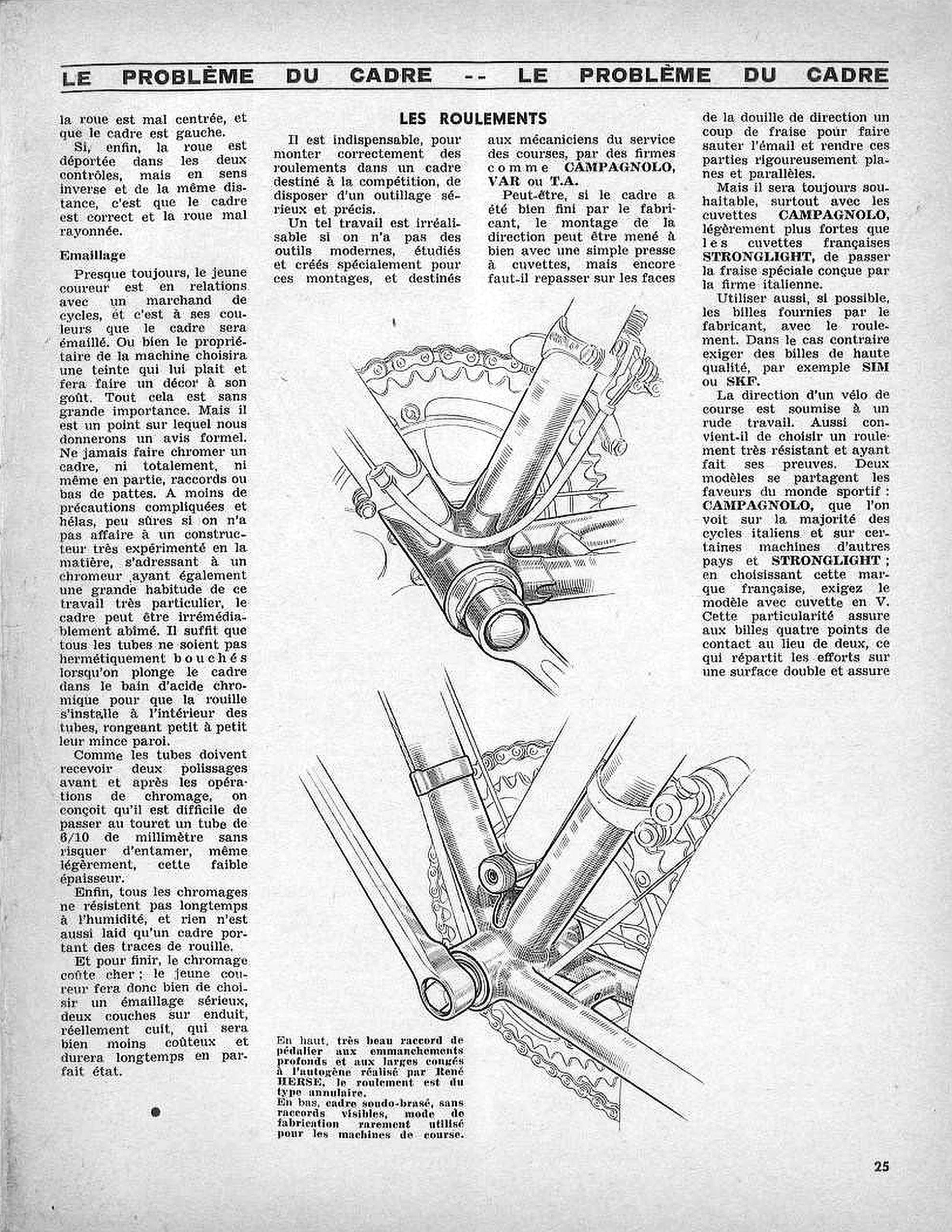
[Ebykr summary; the article’s text is not reproduced. The page finishes the wheel test begun on page 24: a wheel that is centered the first time but off center once reversed means a badly centered wheel in a crooked frame, while a wheel off center in both tests, by the same distance but on opposite sides, means the frame is correct and the wheel badly built. On enameling (Emaillage), the author notes that the young racer is nearly always linked to a cycle dealer and his frame will be enameled in that dealer’s colors, or else the owner picks a color he likes and a decoration to his taste; none of this matters much. He is firm on one point: never have a frame chrome plated, wholly or in part, lugs or dropout ends included. Short of complicated and, alas, unreliable precautions, which need a builder very experienced in the matter and a plater equally used to this special work, the frame can be ruined beyond repair: if any tube is not sealed airtight when the frame is dipped in the chromic acid bath, rust settles inside and slowly eats the thin tube wall. Since the tubes must be polished twice, before and after plating, a tube of 6/10 of a millimeter can hardly go to the polishing wheel without some risk of cutting into that thin wall. Not all chrome plating resists damp for long, nothing looks worse than a frame marked with rust, and chrome is expensive; the young racer would do better to choose a serious enamel finish, two coats over a primer and properly baked, which costs far less and stays in perfect condition for a long time. Under the heading on bearings, the author says that fitting the bearings of a competition frame correctly needs serious, precise tools: modern tools designed and made for this work and intended for race-service mechanics, by firms such as CAMPAGNOLO, VAR or T.A. If the builder finished the frame well, the headset can perhaps be fitted with a simple cup press, but the faces of the head tube must still be skimmed with a cutter to remove the enamel and make them strictly flat and parallel. It is always better, particularly with CAMPAGNOLO cups, which are slightly heavier than the French STRONGLIGHT cups, to use the special cutter designed by the Italian firm. The balls supplied with the bearing by its maker should be used if possible; otherwise insist on high-quality balls, for example SIM or SKF. A racing headset works hard, so a very strong and proven bearing should be chosen. Two models share the favor of the racing world: CAMPAGNOLO, seen on most Italian cycles and on some machines from other countries, and STRONGLIGHT; with the French make, the buyer should insist on the model with the V-shaped cup, which gives the balls four points of contact instead of two and so spreads the loads over twice the surface (the sentence continues on page 26). The caption describes the upper drawing as a very handsome bottom bracket lug with deep sockets and wide oxy-acetylene fillets made by René HERSE, its bearing of the annular type, and the lower drawing as a bronze-welded frame without visible lugs, a method rarely used for racing machines.]
[Two drawings in perspective of the bottom bracket area, set one above the other in the center and right of the page. The upper drawing shows the René HERSE bottom bracket lug with its deep sockets and fillets, the bearing cup and crank, the front derailleur clamped to the seat tube, the chainwheel and chain, and a cable running under the bottom bracket. The lower drawing shows a bronze-welded frame without lugs at the bottom bracket, with a band clamp on the seat tube, a cable roller near the bottom bracket, the crank and the chain. Neither drawing carries a “Rebour” signature; the page has no signed drawing.]
25
— Page 11 —
LE PROBLÈME DU CADRE — LE PROBLÈME DU CADRE
POUR LE RANDONNEUR ET LE CYCLO-SPORTIF
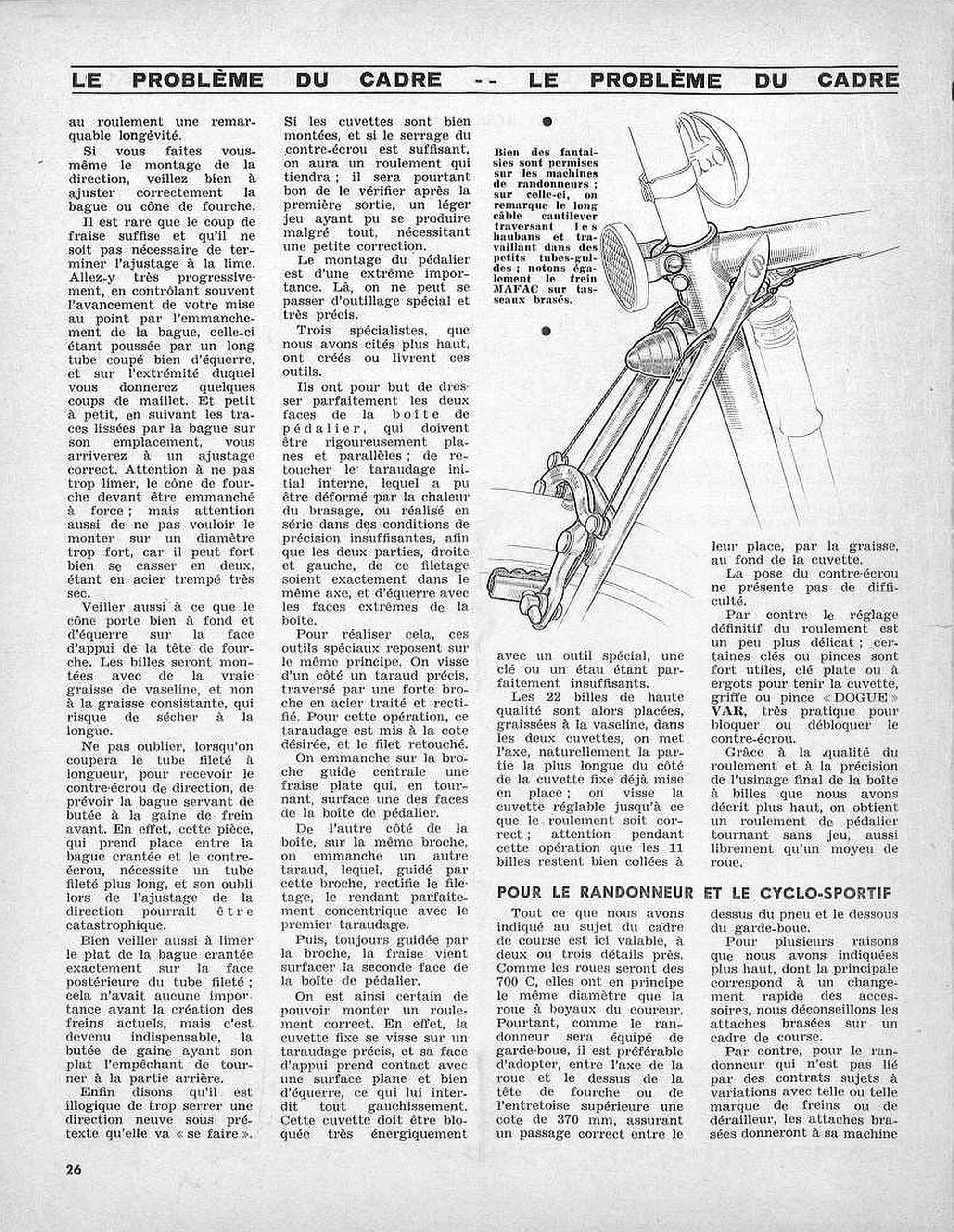
[Ebykr summary; the article’s text is not reproduced. The page opens by finishing the sentence from page 25: the V-shaped STRONGLIGHT cup gives the headset a remarkably long life. Anyone fitting his own headset must fit the fork race (the crown race or cone) with care. The cutter alone is rarely enough and the fit usually has to be finished with a file, working very gradually and checking progress often by driving the race on with a long, squarely cut tube struck with a few mallet blows, and following the polished marks the race leaves on its seat. The race must not be filed too far, since it has to be a force fit, nor forced onto too large a diameter, since it is very hard tempered steel and can easily split in two; it must sit fully home and square on the bearing face of the fork crown. The balls should go in with real Vaseline grease, not thick grease, which can dry out over time. When the threaded steerer is cut to length for the headset locknut, room must be left for the ring that serves as the front brake cable stop; it sits between the keyed washer and the locknut, needs a longer thread, and forgetting it could be catastrophic. The flat of the keyed washer must also be filed to match the flat at the back of the steerer, which mattered little before present-day brakes but is now essential, because the cable stop relies on that flat to keep from turning. It makes no sense to overtighten a new headset on the pretext that it will bed in; with well-fitted cups and a firmly tightened locknut the bearing will hold, though it should be checked after the first ride for slight play. Fitting the bottom bracket is extremely important and needs special, very precise tools, made or supplied by the three specialists named earlier (CAMPAGNOLO, VAR and T.A., on page 25). They face both sides of the bottom bracket shell flat and parallel and true up its threads, which brazing heat may have distorted or production work cut imprecisely, so that the right and left threads share one axis and are square with the end faces. All rest on one principle: a precise tap is screwed into one side, with a strong pilot of hardened, ground steel through it, bringing that thread to size; a flat cutter on the pilot faces that side; a second tap on the same pilot recuts the other thread concentric with the first; the cutter then faces the second side. The fixed cup then screws into an accurate thread and seats against a flat, square face that keeps it from distorting; it must be locked very hard with a special tool, a spanner or vise being quite inadequate. The 22 high-quality balls go into the two cups greased with Vaseline, the axle goes in with its longer end toward the fixed cup, and the adjustable cup is screwed in until the bearing runs correctly, taking care that the 11 balls stay held in the bottom of the cup by the grease. The locknut is easy to fit, but final adjustment is more delicate: a flat or pin spanner to hold the cup and the VAR «DOGUE» claw or pliers, very handy for locking or freeing the locknut, are most useful. With a good bearing and the precise final machining of the shell, the bottom bracket turns without play, as freely as a wheel hub. In the section for the randonneur and the cyclo-sportif, the author says everything said about the racing frame holds, with two or three exceptions. The wheels will be 700 C and so in principle the same diameter as the racer’s tubular-tired wheels, but because the randonneur fits mudguards, a dimension of 370 mm from the wheel axle to the top of the fork crown or of the upper rear bridge is preferable, giving proper clearance between the top of the tire and the underside of the mudguard. For the reasons given earlier, chiefly the quick change of accessories, the author advises against brazed-on fittings on a racing frame; but for the randonneur, who is not bound by changing contracts with one make of brake or derailleur or another, brazed-on fittings will give his machine (the sentence continues on page 27). The caption says that many fancies are allowed on randonneur machines: on this one the long cantilever cable crosses the seat stays and runs in small guide tubes, and the MAFAC brake is mounted on brazed-on bosses.]
[One drawing in perspective at upper right shows the seat cluster of a randonneur machine from behind: a domed fitting clamped to the seat post, a round ribbed lens (a lamp or reflector) at the seat lug, a bullet-shaped fitting between the seat stays, a pump along the seat tube, the long brake cable running through small guide tubes on the stays, the cantilever brake on its brazed-on bosses, and the arc of the mudguard and tire. The drawing carries no “Rebour” signature; the page has no signed drawing.]
26
— Page 12 —
LE PROBLÈME DU CADRE — LE PROBLÈME DU CADRE
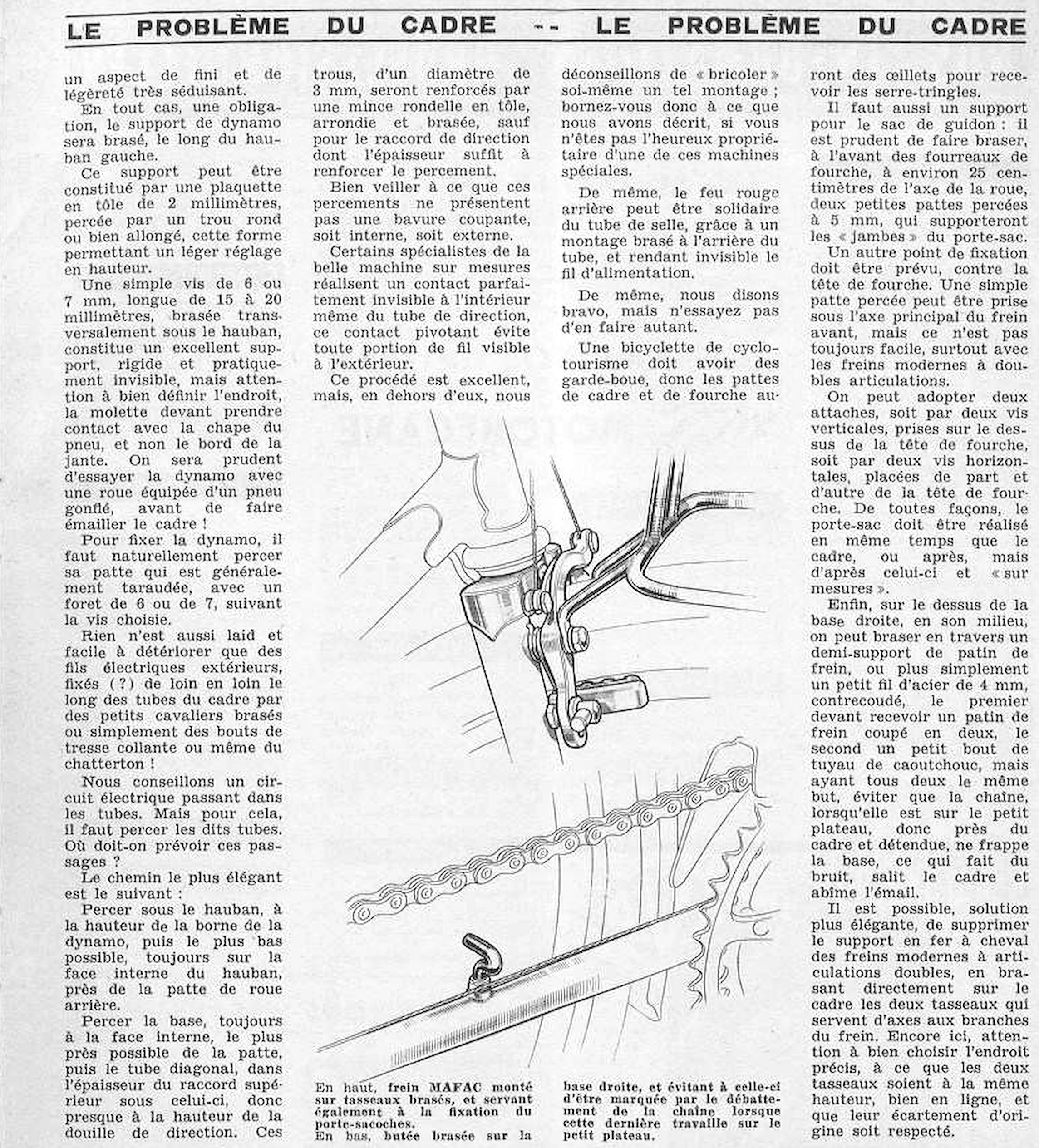
[Ebykr summary; the article’s text is not reproduced. The page finishes the sentence from page 26: brazed-on fittings give the randonneur’s machine a very attractive look of finish and lightness. A dynamo support must in any case be brazed along the left seat stay. It can be a plate of 2 mm sheet steel with a round or elongated hole, the slot allowing a little height adjustment; or simply a screw of 6 or 7 mm, 15 to 20 mm long, brazed crosswise under the stay, an excellent support that is rigid and practically invisible. Its place must be chosen so that the dynamo roller bears on the tire sidewall and not on the rim edge, and the dynamo should be tried with a wheel carrying an inflated tire before the frame is enameled; its bracket, usually threaded, is drilled out with a 6 or 7 drill to suit the screw. Nothing is uglier or more easily damaged than outside electric wires held along the tubes by small brazed clips, adhesive tape or even insulating tape (chatterton), so the author recommends wiring run inside the tubes. The most elegant route: holes under the seat stay at the height of the dynamo terminal and as low as possible on its inner face near the rear dropout; a hole in the inner face of the chainstay close to the dropout; then the down tube, through the thickness of the head lug, almost level with the head tube. These 3 mm holes are reinforced by a thin, rounded sheet-steel washer brazed on, except at the head lug, which is thick enough, and must have no sharp burr inside or out. Some specialists of the fine made-to-measure machine build a perfectly invisible pivoting contact inside the head tube itself, so that no wire shows outside; the procedure is excellent, but the author advises readers not to improvise it themselves. Likewise the red rear lamp can be fixed to the seat tube by a mount brazed behind it, hiding its feed wire; again admirable, but not to be attempted at home. A touring (cyclotourisme) bicycle must have mudguards, so its frame and fork dropouts will carry eyelets for the stay clips. A handlebar bag support is also needed: two small tabs drilled at 5 mm, brazed to the front of the fork blades about 25 centimeters from the wheel axle, carry the legs of the bag carrier. Another fixing is needed at the fork crown: a simple drilled tab under the main bolt of the front brake, not always easy with modern double-pivot brakes, or two screws, either vertical on top of the crown or horizontal on each side of it; in any case the carrier is made at the same time as the frame, or afterward but made to measure for it. On top of the right chainstay, at its middle, one can braze crosswise a half brake-shoe holder or more simply a 4 mm steel wire with a double bend, carrying respectively half a brake shoe or a short piece of rubber tube, so that the slack chain on the small chainring does not slap the stay, which makes noise, dirties the frame and chips the enamel. A more elegant solution is to do away with the horseshoe-shaped mounting of modern double-pivot brakes by brazing to the frame the two bosses on which the brake arms pivot, taking care that both sit at the same height, well aligned and at their original spacing. The caption describes the upper drawing as a MAFAC brake mounted on brazed bosses that also serve to fix the pannier carrier (porte-sacoches), and the lower drawing as a stop brazed on the right chainstay that keeps it from being marked by the chain’s slap when the chain runs on the small chainring. The text ends on this page with the sentence on the brake bosses; no signature and no continuation notice is printed.]
[Two drawings in perspective, one above the other at the center of the page. The upper drawing shows the fork crown and the top of a fork blade, with the brake arm and its shoe pivoting on a brazed boss and the bent tube of a carrier fixed to the same boss, and the arcs of the tire and mudguard behind. The lower drawing shows the right chainstay with a hooked steel wire stop brazed across its top, the chain running above it and the teeth of the chainwheel at right. The drawings carry no “Rebour” signature; the page has no signed drawing.]
Ebykr presents this material for research and education. If you hold rights to it or notice an ownership issue, please contact us and we will respond promptly.
The Ebykr Digest
New articles, timelines, catalog finds and registry activity — assembled from the archive once a month. Your address is never shared.
Double opt-in. One email per month. Unsubscribe at any time with one click.