About Ebykr
Ebykr celebrates classic and vintage lightweight bicycles through provocative imagery and opinion. Ride along with us.
About Ebykr
Ebykr celebrates classic and vintage lightweight bicycles through provocative imagery and opinion. Ride along with us.

Source: Gallica (Bibliothèque nationale de France), L'Officiel du cycle, du motocycle et du camping, 20 September 1952, Numéro spécial du Salon 1952, pages 163 and 165; ark:/12148/bd6t541820671. Source gallica.bnf.fr / BnF.
| Type | Review |
|---|---|
| Year | 1952 |
| Publisher | L'Officiel du cycle |
| Country | France |
| Language | French |
| Pages | 2 |
| Source | Gallica (Bibliothèque nationale de France), L'Officiel du cycle, du motocycle et du camping, 20 September 1952, Numéro spécial du Salon 1952, pages 163 and 165; ark:/12148/bd6t541820671. Source gallica.bnf.fr / BnF. |
| Credit | Ebykr archive; Bibliothèque nationale de France |
| Identifier | Gallica (BnF) ark:/12148/bd6t541820671/f163 |
| Transcription | Headings and specifications transcribed; article text summarized |
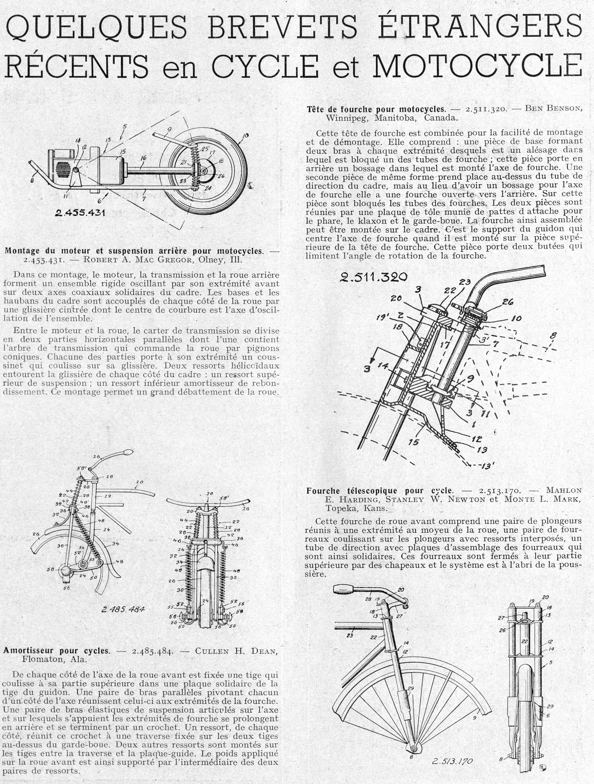
QUELQUES BREVETS ÉTRANGERS RÉCENTS en CYCLE et MOTOCYCLE 2.455.431 Montage du moteur et suspension arrière pour motocycles. — 2.455.431. — ROBERT A. MAC GREGOR, Olney, Ill. 2.485.484 Amortisseur pour cycles. — 2.485.484. — CULLEN H. DEAN, Flomaton, Ala. Tête de fourche pour motocycles. — 2.511.320. — BEN BENSON, Winnipeg, Manitoba, Canada. 2.511.320 Fourche télescopique pour …
This is a magazine article, so its running text is summarized here rather than reproduced; the headline, byline, specifications and scores are transcribed as printed.
From L’Officiel du cycle, du motocycle et du camping, 20 September 1952, the paper’s special number for the 1952 Paris Salon du Cycle et du Motocycle, pages 163 and 165: a selection of recent foreign patents for the cycle and motorcycle, each with its drawing. The title, headings, captions and lists are transcribed as printed; the text is summarized in Ebykr’s words, and the page images carry it in full.
— Page 1 —
QUELQUES BREVETS ÉTRANGERS
RÉCENTS en CYCLE et MOTOCYCLE
2.455.431
Montage du moteur et suspension arrière pour motocycles. — 2.455.431. — ROBERT A. MAC GREGOR, Olney, Ill.
[Ebykr summary; the article’s text is not reproduced. In this mounting the engine, the transmission and the rear wheel form a rigid assembly oscillating by its forward end on two coaxial axes fixed to the frame. The chainstays and the seatstays of the frame are coupled on each side of the wheel by a curved slideway whose center of curvature is the assembly’s axis of oscillation.]
[Ebykr summary, continuing the same patent note. Between the engine and the wheel the transmission case divides into two parallel horizontal parts, one of which holds the drive shaft that drives the wheel through bevel pinions. Each part carries at its end a bearing that slides on its slideway. Two helical springs surround the slideway on each side of the frame: an upper suspension spring and a lower rebound damping spring. The mounting is said to permit a large travel of the wheel.]
2.485.484
Amortisseur pour cycles. — 2.485.484. — CULLEN H. DEAN, Flomaton, Ala.
[Ebykr summary; the article’s text is not reproduced. On each side of the front wheel axle is fixed a rod that slides at its upper part in a plate fixed to the handlebar stem. A pair of parallel arms, each pivoting on one side of the axle, join the axle to the fork ends. A pair of elastic suspension arms articulated on the axle, on which the fork ends bear, extend rearward and finish in a hook. A spring on each side joins this hook to a crossbar fixed on the two rods above the mudguard. Two further springs are mounted on the rods between the crossbar and the guide plate. The weight applied to the front wheel is thus carried through the two pairs of springs.]
Tête de fourche pour motocycles. — 2.511.320. — BEN BENSON, Winnipeg, Manitoba, Canada.
[Ebykr summary; the article’s text is not reproduced. This fork crown is combined for ease of assembly and dismantling. It comprises a base piece forming two arms, at each end of which is a bore in which one of the fork tubes is clamped; this piece carries at the rear a boss in which the fork axle is mounted. A second piece of the same form takes its place above the head tube of the frame, but instead of having a boss for the fork axle it has a fork open toward the rear. On this piece the fork tubes are clamped. The two pieces are joined by a sheet metal plate fitted with attachment lugs for the headlamp, the horn and the mudguard. The fork so assembled can be mounted on the frame. It is the handlebar support that centers the fork axle when it is mounted on the upper piece of the fork crown. This piece carries two stops that limit the angle of rotation of the fork.]
2.511.320
Fourche télescopique pour cycle. — 2.513.170. — MAHLON E. HARDING, STANLEY W. NEWTON et MONTE L. MARK, Topeka, Kans.
[Ebykr summary; the article’s text is not reproduced. This front wheel fork comprises a pair of plungers joined at one end to the wheel hub, a pair of sheaths sliding on the plungers with springs interposed, and a head tube with assembly plates for the sheaths, which are thereby made solid with it. The sheaths are closed at their upper part by caps and the system is sheltered from dust.]
2.513.170
[A page of text and patent drawings set in two columns, without rules between them. Each note is a short paragraph of roman text under a run-in heading whose first words are in bold, followed by the patent number and the patentee’s name in small capitals with the town beneath. The drawings are line engravings reproduced from the patent sheets, in outline with hatched sections and with the reference numbers lettered by hand in a sloping script; each sheet carries its patent number lettered in the same hand. At the head of the first column, figure 2.455.431 shows a motorcycle in side elevation reduced to its rear half: a finned engine unit at the left with an exhaust pipe curving down and forward, a horizontal transmission case running back to the rear wheel, the spoked wheel drawn as concentric circles with a heavy tire, and two helical springs above and below the axle where the case meets a curved slideway, every part numbered from 5 to 26. Lower in the first column, figure 2.485.484 shows two views of a sprung front end: at the left a side elevation of the fork, mudguard, handlebar and the pivoting arms with their long springs, at the right a front elevation of the same fork with a pair of tall coil springs flanking the steerer, numbered from 10 to 58. At the head of the second column, figure 2.511.320 is a large sectional elevation of a motorcycle fork crown seen from the side, the tubes and the clamped pieces drawn in section with hatching, the handlebar sweeping up at the upper right and the outline of the headlamp and mudguard indicated in broken lines. Lower in the second column, figure 2.513.170 shows at the left a side elevation of the front of a bicycle with its fork, mudguard, spoked wheel and handlebar, and at the right a front elevation of the telescopic fork with its assembly plates and caps. No artist’s signature appears on any of the drawings.]
— Page 2 —
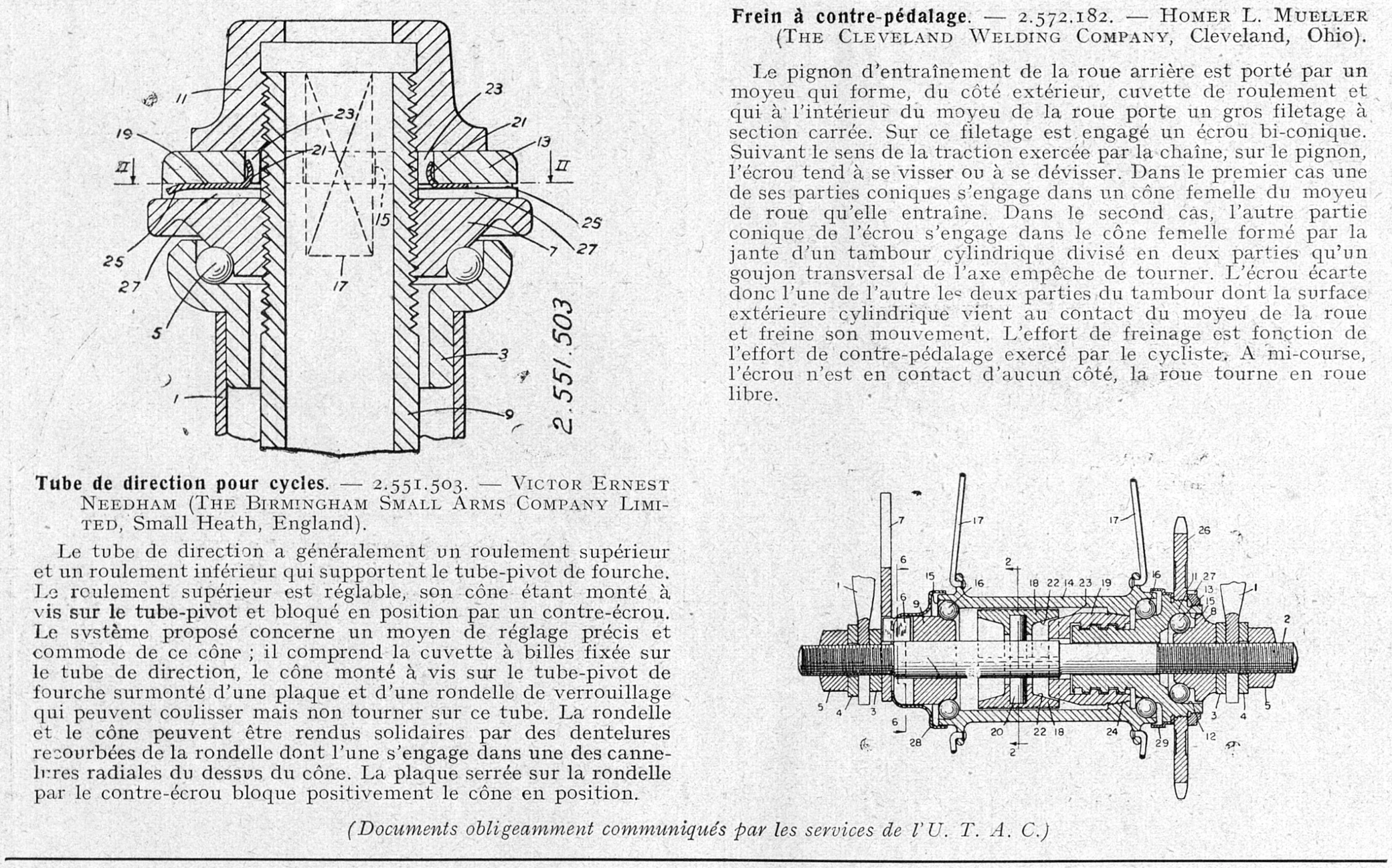
2.551.503
Tube de direction pour cycles. — 2.551.503. — VICTOR ERNEST NEEDHAM (THE BIRMINGHAM SMALL ARMS COMPANY LIMITED, Small Heath, England).
[Ebykr summary; the article’s text is not reproduced. The head tube generally has an upper bearing and a lower bearing that carry the fork steerer tube. The upper bearing is adjustable, its cone being screwed onto the steerer and locked in position by a locknut. The system proposed concerns a means of precise and convenient adjustment of that cone; it comprises the ball cup fixed on the head tube, the cone screwed onto the fork steerer and surmounted by a plate and a locking washer that can slide but not turn on that tube. The washer and the cone can be made solid with one another by bent-over teeth of the washer, one of which engages in one of the radial splines on the top of the cone. The plate, clamped onto the washer by the locknut, blocks the cone positively in position.]
Frein à contre-pédalage. — 2.572.182. — HOMER L. MUELLER (THE CLEVELAND WELDING COMPANY, Cleveland, Ohio).
[Ebykr summary; the article’s text is not reproduced. The rear wheel driving sprocket is carried by a hub that forms, on the outer side, a bearing cup, and that inside the wheel hub carries a coarse square-section thread. On this thread is engaged a bi-conical nut. According to the direction of the traction exerted by the chain on the sprocket, the nut tends to screw up or to unscrew. In the first case one of its conical parts engages in a female cone of the wheel hub, which it drives. In the second case the other conical part of the nut engages in the female cone formed by the rim of a cylindrical drum divided into two parts, which a transverse stud on the axle prevents from turning. The nut therefore forces the two parts of the drum apart, and their outer cylindrical surface comes into contact with the wheel hub and brakes its movement. The braking effort is a function of the back-pedaling effort exerted by the cyclist. At mid-travel the nut is in contact on neither side and the wheel turns freewheel.]
(Documents obligeamment communiqués par les services de l’U. T. A. C.)
[Half a page of text and patent drawings in two columns, closed at the foot by a heavy rule. Each note is a short paragraph of roman text under a run-in heading whose first words are in bold, followed by the patent number and the patentee’s name in small capitals, with the company and town in parentheses. The drawings are line engravings taken from the patent sheets, drawn wholly in section with close diagonal hatching, their reference numbers lettered by hand in a sloping script. At the head of the first column, figure 2.551.503 is a large axial section of a bicycle head tube and fork steerer seen from the front, showing the ball races with their balls, the threaded steerer, the screwed cone with the toothed washer and plate above it and the locknut, the parts numbered from 1 to 27, with a section line II marked on each side and the patent number lettered vertically up the right-hand edge of the figure. In the second column, below the text, a wide axial section of a coaster brake rear hub shows the axle with its threaded ends and cones, the ball races, the driving sprocket, the bi-conical nut on its square thread and the split brake drum, with the spoke flanges indicated at each end and a section line 2 marked across the middle; the parts are numbered from 1 to 29 and the figure carries no patent number. The credit line sits alone at the foot, set in italic. No artist’s signature appears on either drawing.]
Ebykr presents this material for research and education. If you hold rights to it or notice an ownership issue, please contact us and we will respond promptly.
The Ebykr Digest
New articles, timelines, catalog finds and registry activity — assembled from the archive once a month. Your address is never shared.
Double opt-in. One email per month. Unsubscribe at any time with one click.