About Ebykr
Ebykr celebrates classic and vintage lightweight bicycles through provocative imagery and opinion. Ride along with us.
About Ebykr
Ebykr celebrates classic and vintage lightweight bicycles through provocative imagery and opinion. Ride along with us.

Source: L'Officiel du cycle, du motocycle et du camping, N° 37, 3 November 1951, pages 5 and 7; scan of the issue from Cycle Memory (Mémoire du Cycle), Collection privée F.
| Type | Review |
|---|---|
| Year | 1951 |
| Publisher | L'Officiel du cycle |
| Country | France |
| Language | French |
| Pages | 2 |
| Source | L'Officiel du cycle, du motocycle et du camping, N° 37, 3 November 1951, pages 5 and 7; scan of the issue from Cycle Memory (Mémoire du Cycle), Collection privée F. |
| Credit | Ebykr archive |
| Identifier | Permalink https://cyclememory.org/fr/search-coll-list.php?collectionID=325&docID=B-1-0000001003 |
| Transcription | Headings and specifications transcribed; article text summarized |
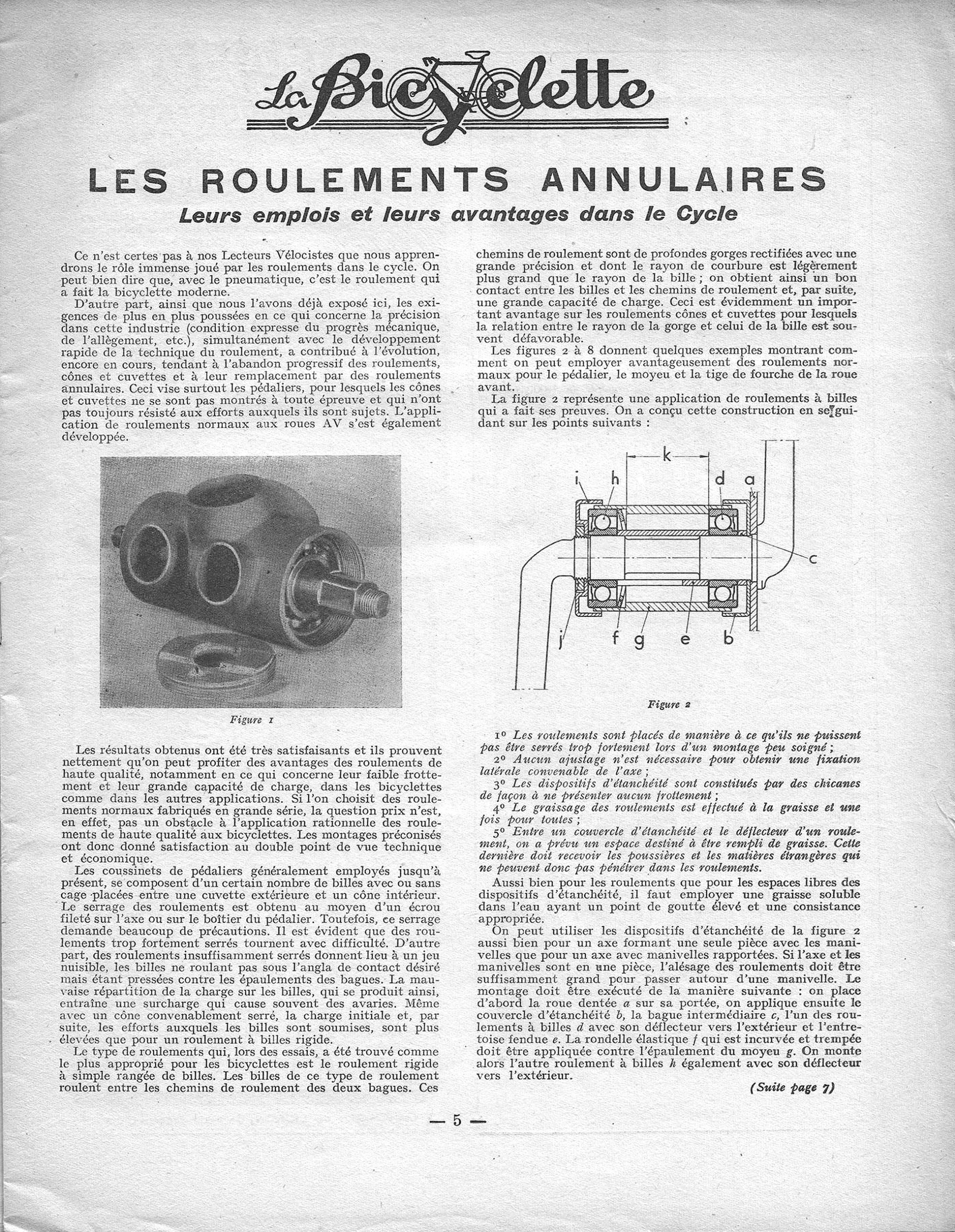
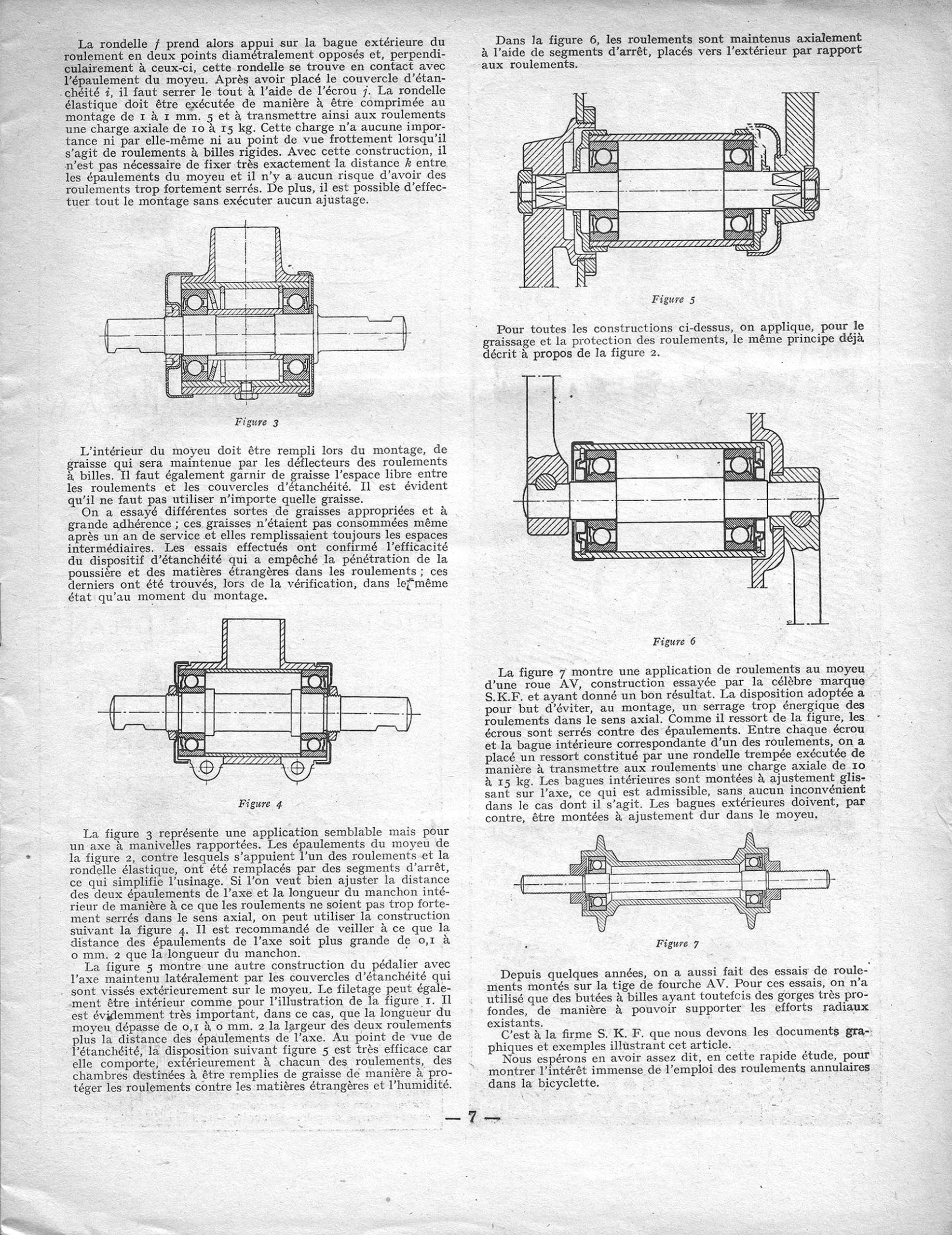
La Bicyclette LES ROULEMENTS ANNULAIRES Leurs emplois et leurs avantages dans le Cycle 1° 2° 3° 4° 5° Figure 1 k i h d a c j f g e b Figure 2 (Suite page 7) — 5 — Figure 3 Figure 4 Figure 5 Figure 6 Figure 7 — 7 —
This is a magazine article, so its running text is summarized here rather than reproduced; the headline, byline, specifications and scores are transcribed as printed.
“Les Roulements annulaires, leurs emplois et leurs avantages dans le cycle”, an unsigned technical article in L’Officiel du cycle, du motocycle et du camping, 3 November 1951: why annular ball bearings were replacing cups and cones in the bicycle bottom bracket, hubs and steering head, with S.K.F. sectional drawings and the order of assembly. The headings and figure labels are transcribed as printed; the text is summarized in Ebykr’s words, and the page images carry it in full.
— Page 1 —
La Bicyclette
LES ROULEMENTS ANNULAIRES
Leurs emplois et leurs avantages dans le Cycle
1° 2° 3° 4° 5°
[Ebykr summary of the numbered list; its text is not reproduced. The five principles of the Figure 2 bottom bracket: the bearings are placed so that careless assembly cannot overtighten them; no adjustment is needed to locate the axle sideways; the seals are labyrinths (“chicanes”) with no rubbing contact; the bearings are greased once and for all; and a space between each seal cover and the bearing’s deflector is filled with grease to catch dust and foreign matter before it reaches the bearing.]
Figure 1
k
i h d a
c
j f g e b
Figure 2
(Suite page 7)
[Ebykr summary; the article’s text is not reproduced. The unsigned article, printed under the section heading “La Bicyclette”, opens by telling its readers, the cycle dealers (“Lecteurs Vélocistes”), that after the pneumatic tire the bearing is what made the modern bicycle. The trade’s growing demand for precision and lightness, together with progress in bearing technique, is driving the gradual abandonment of cup-and-cone bearings (“roulements, cônes et cuvettes”) in favor of annular bearings (“roulements annulaires”), above all in the bottom bracket (“pédalier”), where cups and cones have not always stood up to the loads; standard bearings (“roulements normaux”) are also being fitted to front wheels (“roues AV”). Trials showed low friction and high load capacity, and mass production keeps the price down. The usual bottom-bracket bearing, balls (caged or loose) between an outer cup (“cuvette extérieure”) and an inner cone (“cône intérieur”) adjusted by a threaded nut, turns hard when overtightened and, when loose, has play that loads the balls against the race shoulders instead of at the intended contact angle, causing damage. The type found best in trials is the rigid single-row ball bearing (“roulement rigide à simple rangée de billes”), whose deep ground raceways (“profondes gorges rectifiées”) have a radius slightly larger than the ball’s, giving good contact and high load capacity, unlike cups and cones. Figures 2 to 8 are said to show standard bearings in the bottom bracket, the hub (“moyeu”) and the front fork steerer (“tige de fourche”). Figure 2 shows a proven ball-bearing bottom bracket designed on five principles, set out in a numbered list. The page recommends a water-soluble grease with a high drop point (“point de goutte”) for both the bearings and the seal spaces, and says the Figure 2 seals suit both a one-piece axle-and-cranks (“une seule pièce avec les manivelles”) and an axle with separate cranks (“manivelles rapportées”); with a one-piece crank the bearing bore must be large enough to pass over a crank. It then gives the assembly order by the figure’s letters: chainwheel (“roue dentée”) a on its seat, seal cover (“couvercle d’étanchéité”) b, intermediate ring (“bague intermédiaire”) c, ball bearing d with its deflector outward, split spacer (“entretoise fendue”) e, the curved hardened spring washer (“rondelle élastique”) f against the shoulder of the shell (“moyeu”) g, then the second ball bearing h, deflector outward (continued on page 7).]
[Figure 1 is a halftone photograph of a bottom-bracket shell with its tube sockets, an annular ball bearing visible inside the open right-hand end and the axle protruding from it, with a threaded cup or seal cover lying in front of the shell. Figure 2 is a sectional line drawing of a bottom bracket fitted with two annular ball bearings, the crank and the frame tubes shown in part, lettered a to k: a on the plate at the right end, b the cover at lower right, c a ring at right pointed to by a leader line, d the right-hand bearing, e a spacer below the axle, f the curved washer beside the left-hand bearing, g the shell, h the left-hand bearing, i the cover at upper left, j the nut at lower left and k a dimension arrow spanning the distance between the shoulders at the top. Neither figure carries a signature or monogram.]
— 5 —
— Page 2 —
Figure 3
Figure 4
Figure 5
Figure 6
Figure 7
[Ebykr summary; the article’s text is not reproduced. (Continued from page 5.) Completing the Figure 2 bottom bracket, the article explains that the spring washer f bears on the bearing’s outer ring at two diametrically opposite points and on the shell shoulder at right angles to them; after the seal cover i is fitted, the whole is tightened with the nut j. The washer is made to compress by 1 to 1.5 mm in assembly, putting an axial load of 10 to 15 kg on the bearings, which matters neither in itself nor for friction with rigid ball bearings, so the distance k between the shoulders need not be held exactly, the bearings cannot be overtightened and no fitting work is needed. The shell is packed with grease held in by the bearings’ deflectors, and the space between bearings and seal covers is greased too, though not with just any grease: high-adhesion greases tested were not used up after a year in service, and on inspection the seals had kept out dust and foreign matter, the bearings being found as they were when fitted. Figure 3 applies the same design to an axle with separate cranks (“manivelles rapportées”), the shoulders of Figure 2 replaced by snap rings (“segments d’arrêt”), which simplifies machining. To keep the bearings from being clamped axially, Figure 4 can be used, the axle shoulders set 0.1 to 0.2 mm farther apart than the length of the inner sleeve (“manchon”). Figure 5 holds the axle laterally by seal covers screwed onto the outside of the shell (an internal thread, as in Figure 1, also works), the shell then exceeding the width of both bearings plus the shoulder distance by 0.1 to 0.2 mm; its grease chambers outside each bearing protect against dirt and damp. In Figure 6 the bearings are held axially by snap rings placed outboard. The lubrication and sealing principle of Figure 2 applies to all these designs. Figure 7, a front-wheel hub (“moyeu d’une roue AV”) tried by the well-known make S.K.F. with good results, has its nuts tightened against shoulders and a hardened spring washer between each nut and inner ring giving an axial load of 10 to 15 kg; the inner rings are a sliding fit on the axle and the outer rings a tight fit in the hub. For some years ball bearings have also been tried on the front fork steerer (“tige de fourche AV”), using only ball thrust bearings (“butées à billes”) with very deep grooves to take the radial loads. The drawings and examples are credited to the firm S. K. F., and the article closes on the great value of annular bearings in the bicycle.]
[Five sectional line drawings, unlettered, each with its caption. Figure 3 shows a bottom-bracket shell with its seat-tube socket, two annular ball bearings, a spring washer beside the left bearing and an axle with cotter flats at both ends. Figure 4 shows a similar bottom bracket whose axle carries two shoulders inside the shell, with two pierced lugs below the shell. Figure 5 shows a bottom bracket in a frame with seal covers outside each bearing, the cranks held on the axle ends by nuts, with a curved cover at the right. Figure 6 shows a bottom bracket with the bearings held by snap rings, the cranks fixed by cotters shown in section. Figure 7 shows a front hub with two flanges, an annular ball bearing in each end and a threaded axle. None of the drawings carries a signature or monogram.]
— 7 —
Ebykr presents this material for research and education. If you hold rights to it or notice an ownership issue, please contact us and we will respond promptly.
The Ebykr Digest
New articles, timelines, catalog finds and registry activity — assembled from the archive once a month. Your address is never shared.
Double opt-in. One email per month. Unsubscribe at any time with one click.